EP0342242A1 - Verfahren zur verarbeitung von bilddaten auf basis von strassenspaltungen - Google Patents
Verfahren zur verarbeitung von bilddaten auf basis von strassenspaltungen Download PDFInfo
- Publication number
- EP0342242A1 EP0342242A1 EP88909386A EP88909386A EP0342242A1 EP 0342242 A1 EP0342242 A1 EP 0342242A1 EP 88909386 A EP88909386 A EP 88909386A EP 88909386 A EP88909386 A EP 88909386A EP 0342242 A1 EP0342242 A1 EP 0342242A1
- Authority
- EP
- European Patent Office
- Prior art keywords
- crack
- determination
- pursuing
- existent
- line
- Prior art date
- Legal status (The legal status is an assumption and is not a legal conclusion. Google has not performed a legal analysis and makes no representation as to the accuracy of the status listed.)
- Withdrawn
Links
Images


Classifications
-
- G—PHYSICS
- G06—COMPUTING OR CALCULATING; COUNTING
- G06T—IMAGE DATA PROCESSING OR GENERATION, IN GENERAL
- G06T7/00—Image analysis
- G06T7/60—Analysis of geometric attributes
-
- G—PHYSICS
- G06—COMPUTING OR CALCULATING; COUNTING
- G06T—IMAGE DATA PROCESSING OR GENERATION, IN GENERAL
- G06T7/00—Image analysis
- G06T7/0002—Inspection of images, e.g. flaw detection
- G06T7/0004—Industrial image inspection
- G06T7/0006—Industrial image inspection using a design-rule based approach
-
- G—PHYSICS
- G06—COMPUTING OR CALCULATING; COUNTING
- G06T—IMAGE DATA PROCESSING OR GENERATION, IN GENERAL
- G06T7/00—Image analysis
- G06T7/10—Segmentation; Edge detection
- G06T7/181—Segmentation; Edge detection involving edge growing; involving edge linking
-
- G—PHYSICS
- G06—COMPUTING OR CALCULATING; COUNTING
- G06V—IMAGE OR VIDEO RECOGNITION OR UNDERSTANDING
- G06V10/00—Arrangements for image or video recognition or understanding
- G06V10/40—Extraction of image or video features
- G06V10/44—Local feature extraction by analysis of parts of the pattern, e.g. by detecting edges, contours, loops, corners, strokes or intersections; Connectivity analysis, e.g. of connected components
- G06V10/457—Local feature extraction by analysis of parts of the pattern, e.g. by detecting edges, contours, loops, corners, strokes or intersections; Connectivity analysis, e.g. of connected components by analysing connectivity, e.g. edge linking, connected component analysis or slices
-
- G—PHYSICS
- G06—COMPUTING OR CALCULATING; COUNTING
- G06T—IMAGE DATA PROCESSING OR GENERATION, IN GENERAL
- G06T2207/00—Indexing scheme for image analysis or image enhancement
- G06T2207/30—Subject of image; Context of image processing
- G06T2207/30248—Vehicle exterior or interior
- G06T2207/30252—Vehicle exterior; Vicinity of vehicle
- G06T2207/30256—Lane; Road marking
Definitions
- the present invention relates to a method of effectively performing a series of processings from recognizing of image data representative of crack derived from measurements for a road surface via extracting of line segments in correspondence to the crack till outputting of results derived from analyzing of a crack occurrence rate or the like.
- a conventional typical measuring system utilizing these automatic techniques is classified into two types, one of them being a slit camera system (as disclosed in an official gazette of Japanese Published Patent NO. 281915/1986) and the other one being a laser light receiving system (as disclosed in specifications of Japanese Patent Application NO. 229563/1983 and Japanese Patent Application NO. 233923/1984).
- an image taking camera, a laser oscillator, a light receiver and other associated components are mounted on a vehicle and this vehicle intended to carry out measurements is caused to move on a road so as to allow image data representative of the road surface to be obtained by automatic measurements.
- image data representative of the road surface derived from measurements for the latter are recorded in a data recorder such as a video tape recorder (VTR) or the like means and the recorded data are later analyzed to evaluate the road surface.
- VTR video tape recorder
- evaluation has been hitherto carried out by a conversation between an operator and a monitor display image surface.
- a tape in which image data representative of the road surface is processed to indicate them on the monitor display via a reproducer.
- a lattice-shaped mesh is placed on the display image surface so as to allow the latter to be divided into a plurality of square regions.
- the operator makes a visual determination as to whether crack is existent or not in the respective divided regions and results derived from the determination are noted on a recording paper in the form of a section paper using marks such as ⁇ , X or the like.
- the present invention has been made with the foregoing background in mind and its object resides in providing a method of processing image data representative of crack which assures that the image data are processed at a high speed with increased accuracy by fully automating a processing of analyzing the image data with the use of a computor.
- an image memory in which data representative of a road surface is divided into a plurality of regions, a determination is made separately for the respective divided regions as to whether or not crack is existent in a predetermined divided region constituting a part selected from the plural divided regions, the region for which a determination is made such that crack is existent is selected as a start point for a pursuing operation, line segments corresponding to the crack are extracted from the selected start point region, the direction of pursuing to be next effected is decided on the basis of the line direction of extension of the extracted line segments, a determination is made as to whether or not crack is existent in adjacent divided regions situated in the direction of pursuing, and line segments are extracted in the region for which a determination is made such that crack is existent.
- a series of processings of pursuing and extracting as mentioned above are repeatedly executed until pursuing is terminated at every start point.
- a start point for a pursuing operation is first selected by partially searching for a divided region. Then, by repeatedly executing the aforementioned processings of pursuing and extracting line segments using the selected start point as an initial point, crack included in a predetermined region is extracted in the form of a combination with line segments.
- a start point for a pursuing operation is selected and thereafter the following processings of pursuing using the selected start point region as an initial point (repeat of a processing of deciding the direction of pursuing, a processing of extracting line segments and a processing of making a determination as to whether crack is existent or not) are performed at every start point.
- the direction of pursuing to be next effected is decided on the basis of the position where a relevant start point region is situated and thereafter a determination is made as to whether or not crack is existent in divided regions adjacent to the start point region.
- a processing of extracting line segments is performed in the adjacent regions.
- a processing of deciding the direction of pursuing, a processing of making a determination as to whether crack is existent or not and a processing of extracting line segments are repeatedly performed in the same manner as mentioned above, whereby crack included in a predetermined region is extracted in the form of a combination with the line segments.
- the direction of pursuing is decided on the basis of a positional relationship between the divided region for which a determination is made at this time such that crack is existent and the divided region for which a determination is made at the preceding time such that crack is existent, and this processing of deciding the direction of pursuing is performed in parallel with the aforementioned processing of extracting line segments.
- the direction of pursuing to be next effected is not decided in dependence on the line direction derived from results in relation to extraction of line segments but it is decided in dependence on a positional relationship between two divided regions for which existence of crack is recognized from results on determination as to whether crack is existent or not. Consequently, according to the present invention, a processing of extracting line segments and a processing of deciding the direction of pursuing can be executed in parallel with each other. This makes it possible to remarkably shorten a time required for processing data in comparison with the method of executing all processings in series.
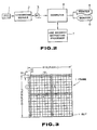
- Fig. 2 schematically illustrates by way of example the structure for carrying out the present invention.
- a video tape 1 is recorded with image data representative of a road surface, wherein the data are measured on a road surface measuring vehicle employing a laser system.
- a converting module 2 is such that the data on an image representative of the road surface recorded in the video tape 1 are quantified, e.g., in the form of eight bits (including 256 tones) in unit represented by 1 mm x 1 mm pixel and they are then written in a magnet tape 3.
- a computor 4 includes an image memory in which the data representative of crack transferred from the magnetic tape 3 in frame unit are stored. It is operated to process the data in the following manner and then output to a printer 5 results derived from the foregoing processing or represent them on a monitor 6. In this case, among a series of data processings, a processing for extracting line segments (to be described later) is executed using an exclusively employable processor 7.
- the computor 4 transfers to an image memory incorporated therein the data representative of cracks on the road surface recorded in the magnetic tape 3 in frame unit (in the form of e.g., 512 x 512 pixels) (step 100). Then, the following analyzing processing is executed in frame unit for the image data which have been transferred in that way.
- the computor 4 is operated so as to allow the image data transferred thereto to cover one frame to be subjected to square slitting as numbered by 16 x 16 as shown in Fig. 3, whereby the image is divided into a number of 16 x 16 square slit regions by slitting in that way (step 120).
- one slit region includes image data in the form of 32 x 32 pixels.
- the computor 4 first executes a processing of "searching for a start point" in relation to crack.
- This processing is intended to search for a start point for the purpose of executing a next processing of pursuing (to be described later).
- This processing of searching for a start point presence or absence of the crack is not recognized over all the slit regions but a determination is made in the order of (1), (2), (3) and (4) only in the slit regions situated below arrow marks (1), (2), (3) and (4) in Fig.3 in the direction as identified by the arrow marks.
- partial limitation of the start point searching regions in that way is based on an idea that a required start point can be detected in any one of the slit regions as long as the regions corresponding to the arrow marks (1), (2), (3) and (4) in Fig. 3 are monitored in view of the fact that crack usually has a certain extent of length.
- the computor 4 is operated to prepare a histogram representing a relationship of the degree of tone to the number of pixels as shown in Fig. 4 in the respective regions and then calculate for the respective slit regions on the basis of the histogram the number N of pixels (corresponding to the hatched part in Fig. 4) remaining less than the threshold ⁇ .
- the computor 4 makes a determination that crack is existent, while when it is found that the number N is less than the preset number N a , it makes a determination that no crack is existent (step 130).
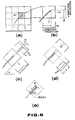
- the computor 4 is operated to carry out a processing of extracting line segments in respective slit regions where a determination is made by the aforementioned start point searching processing such that a start point (representative of crack) is existent (step 140). Specifically, in a case where it is found during this line segment extracting processing that a crack pattern LP as shown, e.g., in Fig. 5(a) is existent, it is extracted as a line segment pattern SG having a rectangular contour as shown in Fig.
- image data are divided into a plurality of square slit regions (represented by 4 x 4 in this case) in the same manner as in Fig. 3 and wave shapes projected in X- and y-directions are then obtained for the respective slit regions (see Figs. 6(a) and (b)).
- an average value (D i : data on density) among density data for a row of pixels (the number of pixels : n′) arranged in the direction of projection is used as values S x and S y indicative of projected wave shape.
- a slit is successively turned by a predetermined angle in the range of 0 to 90 degrees about the center of the respective slit regions so that a projected wave shape is obtained at every turning movement by the predetermined angle.
- a method of obtaining a projected wave shape of the slit as the latter is turned there are proposed two methods, one of them being such that the slit is turned while an image is kept immovable and the other one being such that an image is turned while the the slit is kept immovable.
- the projected wave shape as seen in the direction along a linear pattern LP assumes a maximum peak value P as shown in Fig. 6(c), when the slit region is turned by a certain predetermined angle ⁇ . This permits the direction ⁇ of extension of the linear pattern to be obtained.
- a line width W of the linear pattern is defined by a length W of the line extending tangential to the peak of a projected shape when the latter is subjected to threashold processing with a predetermined threashold T hd1 , as shown, e.g., in Fig. 6(c).
- the length L of the linear pattern is determined as a line length L included in the slit region by restricting the slit region to a crack width W which has been already calculated only in the direction of width thereof, obtaining a projected wave shape with respect to the restricted slit region and then allowing it to be subjected to threashold processing using a certain threashold T hd2 , as shown in Fig. 6(d).
- a simple square slit the peak of a wave shape as seen in the direction along extension of the line appears clearly but the peak of the same as seen in the direction has a reduced optical contrast.
- the linear pattern included in a single slit region can be recognized as a rectangular pattern of which width W, length L and direction ⁇ are already known, as shown in Fig. 6(e). This is called a line segment. Accordingly, when such processings are carried out for respective mesh regions shown in Fig. 6(a), a line pattern of which width W, length L and direction ⁇ are already known can be extracted as a line segment.
- a pursuing start point in the relevant frame is selected by repeating a processing of making a determination as to whether a start point is existent or not and a processing of extracting line segments in accordance with the order of the arrow marks (1), (2), (3) and (4), and line segments are extracted from the selected start point.
- the computor 4 allocates a serial number to the respective slit regions which have been selected by the aforementioned processing of searching for a start point (step 160) and then it executes the following "processing of pursuing" in the order of the allocated numbers.
- the direction of pursuing is determined on the basis of the direction ⁇ of extension of the line segment which has been extracted in the slit region where NO. 1 start point is situated (steps 170 and 180).
- a determination on the direction of pursuing is made as shown, e.g., in Fig. 7.
- a middle slit as represented by hatched lines is defined as a slit from which pursuing is started.
- a middle slit as represented by hatched lines is defined as a slit from which pursuing is started.
- pursuing is effected toward six adjacent slits as represented by arrow marks of solid lines and dotted lines with the exception of adjacent slits located just above and beneath the middle slit.
- next pursuing is effected only toward three slits on the right-hand side as shown by arrow marks of solid lines
- next pursuing is effected only toward the three slits on the left-hand side as shown by arrow marks of dotted lines
- next pursuing is effected toward six slits as shown by arrow marks of solid lines and dotted lines.
- next pursuing is effected toward six slit regions with the exception of the right-lower and left-upper slit regions, as shown in Fig. 7(b).
- next pursuing is effected toward either of three slit regions represented by arrow marks of solid lines and three slit regions represented by arrow marks of dotted lines.
- next pursuing is effected toward six slit region with the exception of the right and left slit regions, as shown in Fig. 7(c).
- next pursuing is effected toward either of three slit regions represented by arrow marks of solid lines and three slit regions represented by arrow marks of dotted lines. Further, when the line direction ⁇ is in the region of 113° ⁇ ⁇ ⁇ 157°, nest pursuing is effected toward six slit regions with the exception of the right-upper and left-lower slit regions, as shown in Fig. 7(d). Alternatively, next pursuing is effected toward either of three slit regions represented by arrow marks of solid lines and three slit regions represented by arrow marks of dotted lines.
- the computor 4 makes a determination using the determination process as shown in Fig. 4 as to whether or not crack is practically existent within the adjacent slit regions located in the directions of pursuing determined in that way and then it extracts line segments using the aforementioned processing of projection only in the slit regions for which a determination has been made such that crack is existent (step 210).
- this is determined as "branching" and line segments are extracted in the respective slit regions where cracks are existent (step 230).
- a determination is made such that no branching occurs and line segments are extracted only in the single slit region where crack is existent (step 210).
- the computor 4 executes a processing of pursuing to be effected from the NO. 1 start point serving as an initial point as well as a processing of extracting line segments by repeatedly executing the processing of pursuing until the pursuing region extends to an end region in one frame or until no crack is recognized in the directions of pursuing.
- the processing of pursuing is terminated (step 220)
- the computor 4 has informations on extracted line segments ( ⁇ , W, L, coordinates representative of segment, coordinates representative of ridge line and others) and informations on slit connectedness (informations representing whether or not line segments are connected between adjacent slits: in this case, when crack is existent in the adjacent slits, a determination is made such that connection is made therebetween) stored in the memory (step 240).
- the computor 4 executes a processing of pursuing and a processing of extracting line segments with respect to a next NO. 2 start point in the same manner as mentioned above (step 250).
- the computor 4 calculates evaluation data such as an occurrence rate of crack on the road surface corresponding to the relevant frame (represented by 512 x 512), a length of the same and so forth using informations on line segments and informations on slit connectedness (step 270).
- the computor 4 transfers from the magnetic tape 3 data on the road surface corresponding to a next frame again (step 280). Thereafter, it executes data processing within the next frame in the same manner as mentioned above.
- Fig. 9 illustrates by way of example a processing of pursuing and a processing of extracting line segments.
- the processing of pursuing and the process of extracting are executed from two start points, i.e., NO. 1 start point and NO. 2 start point.
- a processing of extracting line segments is not executed in all slit regions but informations on line segments corresponding to an image representative of crack are obtained by executing a series of processings comprising searching for a start point, determination on the direction of pursuing, determination as to whether crack is existent or not, extracting of line segments, determination on the direction of pursuing, determination as to whether crack is existent or not, and extracting of line segments. Consequently, the number of processings of extracting line segments can be reduced substantially and a speed required for data processing can be increased substantially.
- FIG. 10 illustrates other embodiment of the present invention.
- a flowchart shown in Fig. 10 is such that a step 212, a step 214 and a step 216 are additionally inserted between the step 210 and the step 220 in the aforementioned flowchart shown in Fig. 1. Accordingly, this embodiment is different from the preceding embodiment only in this regard.
- a slit region for pursuing is determined in a manner shown in Fig. 7 (step 180)
- a determination is made such that crack is existent in the determined slit region (step 190)
- a processing of extracting line segments is performed on the basis of results derived from the determination (steps 210 and 230) and thereafter a processing of removing noise and a processing of making a determination on connectedness as mentioned below are executed in the same manner as in the preceding embodiment.
- noise is removed on the basis of line length L, line width W and line direction ⁇ representative of informations on the extracted line segments (step 212).
- a line segment corresponding to the crack has a line length L which is long to some extent, has a line width W which is not excessively wide and has a relative angle relative to the adjacent segment which is linear to some extent.
- a line segment corresponding to noise has a length L which is short, has a width W which is wide and has a relative angle relative to the adjacent segment which has no directionality.
- the computor 4 makes a determination on connectedness of the line segments which remain after the processing of removing noise. This is because of the fact that the line segments which remain after the processing of removing noise do not necessarily provide data representative of crack but may provide a noise component. In view of this fact, the noise component which can not be removed during the processing of removing noise is removed utilizing a property that data representative of crack are connected between adjacent slits.
- connectedness Determination on connectedness is made in the following manner. Namely, in a case where adjacent segments are connected to each other as shown in Fig. 12, connectedness can simply be determined but some results derived from extraction of line segments reveal that the crack does not reach the surrounding lines of a slit, as shown in Fig. 13(a) in spite of the fact that it practically extends across the slit or it extends beyond the surrounding lines of a slit, as show in in Fig. 13(b).
- intersections e0 and e1 made by ridge lines SL and a boundary between both slits are obtained by prolonging or contracting the ridge lines SL for the extracted line segments and a distance ⁇ between the intersections e0 and e1 is then obtained.
- a determination is made such that the line segments continue one after another and when it is found that ⁇ is more than ⁇ c , a determination is made such that they discontinue (step 214).
- a noise component is removed from extracted line segments and a processing of pursuing is executed only on the basis of line segments corresponding to data representative of crack.
- Fig. 15 illustrates another embodiment of the present invention.
- Fig. 15 is such that steps 161 to 165 are substituted for the steps 170 to 210 and the step 230 in the embodiment shown in Fig. 1 but other steps rather than the aforementioned one are entirely same to the latter. Namely, a method of determining the direction of pursuing and a timing of extracting line segments in this embodiment are substantially different from the embodiment shown in Fig. 1.
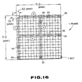
- the computor 4 is operated to select a start point for a pursuing operation in the relevant frame by repeatedly executing a processing of making a determination as to whether a start point is existent or not and a processing of extracting line segments in accordance with the order of the arrow marks (1), (2), (3) and (4) in Fig. 16 in the same manner as in the aforementioned embodiment, extract line segments from the selected start point for a pursuing operation and thereafter allot a serial number to a slit region selected by a processing of searching for a start point to execute the following "processing of pursuing" in accordance with the order of allotted numbers (steps 100 to 160).
- a direction of pursuing to be next effected is determined on the basis of the position assumed by this start point (step 161).
- the direction of pursuing to be next effected is determined in correspondence to a line direction 0 of extracted line segments but in this embodiment the direction of pursuing is determined in correspondence to the position assumed by the start point.
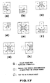
- the start point for a pursuing operation is located at a position identified by (a) in Fig. 16
- a determination is made such that three adjacent slit regions on the right-hand side are recognized as regions to be next pursued, as shown in Fig. 17(a).
- a direction of pursuing to be next effected is determined as shown in Figs. (b), (c), (d), (e), (f), (g) and (h).
- the direction of pursuing operation is specified only in dependence on the position where the start point is situated within the relevant frame.
- the computor 4 makes a determination as to whether or not crack is practically existent within the pursuing slit region determined in that way, using the determination process having a histogram in Fig. 4 employed therefor in the same manner as in the aforementioned embodiment(step 162).
- the computor 4 activates the line segment extracting processor 7 to extract line segments using the aforementioned processing of projecting within the slit region for which a determination has been made such that crack is existent (step 165).
- the computor 4 performs a processing of determining the direction of pursuing to ne next effected in parallel with the processing of extracting line segments (step 164).
- the direction of pursuing is determined on the basis of a positional relationship between the preceding slit for which a determination is made such that crack is existent and the slit determined two times before. Specifically, in a case where pursuing has been effected in the transverse direction (in a case where two slits for which a determination has been made such that crack is existent are located adjacent to each other in the transverse direction), as shown in Figs. 18(a) and (b), a next pursuing operation is performed for three right or left slits.
- a next pursuing operation is performed for three lower or upper slits.
- a next pursuing operation is performed for the shown three slits located obliquely of the middle slit.
- the direction of pursuing to be next effected can not be decided, unless results derived from extraction of the line segments are obtained. Accordingly, in this case, a processing of determining the direction of pursuing and a processing of extracting line segments are performed one after another without fail.
- the direction of pursuing is decided in dependence on a positional relationship between the slit at this time for which a determination is made such that crack is existent and the slit determined at the preceding time.
- the direction of pursuing can be decided at the time when the position assumed by the slit including crack is determined. Accordingly, there is no need of performing the processing of deciding the direction of pursuing after the processing of extracting line segments, and the processing of determining the direction of pursuing and the processing of extracting line segments can be executed after determination as to whether crack is existent or not. This makes it possible to perform data processing at a higher speed at an improved efficiency.
- an occurrence of "branching" is determined (step 163).
- pursuing is first effected in the direction A in the same manner as mentioned above and after completion of this pursuing operation, a next pursuing operation is performed in the direction B.
- the computor 4 executes a processing of pursuing from the NO. 1 start point serving as an initial point as well as a processing of extracting line segments by repeatedly executing such a processing of pursuing in the same manner as in the aforementioned embodiments until the pursuing region reaches an end region within a single frame or until no crack is recognized in the direction of pursuing.
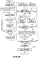
- Fig. 20 schematically illustrates by way of flowchart such a series of processings of pursuing.
- the computor 4 executes the same processings as in the aforementioned embodiments.
- the computor 4 has informations on an extracted line segment ( ⁇ , W, L, coordinates indicative of segments, coordinate indicative of a ridge line and so forth) and informations on slit connectedness (informations representing whether the line segment is connected between adjacent slits or not) stored in the memory (step 230) and thereafter it executes the same processings of pursuing and extracting line segments with respect to the NO. 2 start point in the same manner as mentioned above (step 240).
- the computor 4 calculates evaluation data such as an occurrence rate of crack on the road surface corresponding to the relevant frame (represented by 512 x 512), a length of respective crack or the like using informations on line segments, informations on slit connectedness or the like informations (step 260). After the data processing for the relevant frame is terminated, the computor 4 transfers data on the road surface corresponding to a next frame from the magnetic tape 3 again (step 270). Thereafter, it performs data processing within the next frame in the same manner as mentioned above.
- evaluation data such as an occurrence rate of crack on the road surface corresponding to the relevant frame (represented by 512 x 512), a length of respective crack or the like using informations on line segments, informations on slit connectedness or the like informations (step 260).
- the computor 4 transfers data on the road surface corresponding to a next frame from the magnetic tape 3 again (step 270). Thereafter, it performs data processing within the next frame in the same manner as mentioned above.
- the direction of pursuing is decided in dependence on a positional relationship between two slits to be pursued and a processing of deciding the direction of pursuing and a processing of extracting line segments are performed in parallel with each other, as shown in Fig. 20. Consequently, processings can be achieved at a high efficiency and a time required for data processing can be shortened.
- the present invention is advantageously applicable to a series of computor processings for recognizing crack in image data derived from measurements for the road surface.
Landscapes
- Engineering & Computer Science (AREA)
- Physics & Mathematics (AREA)
- Computer Vision & Pattern Recognition (AREA)
- General Physics & Mathematics (AREA)
- Theoretical Computer Science (AREA)
- Multimedia (AREA)
- Quality & Reliability (AREA)
- Geometry (AREA)
- Image Analysis (AREA)
- Image Processing (AREA)
Applications Claiming Priority (4)
| Application Number | Priority Date | Filing Date | Title |
|---|---|---|---|
| JP270017/87 | 1987-10-26 | ||
| JP62270017A JPH01112382A (ja) | 1987-10-26 | 1987-10-26 | ひびわれ画像データ処理方法 |
| JP280776/87 | 1987-11-06 | ||
| JP28077687A JPH01123374A (ja) | 1987-11-06 | 1987-11-06 | ひびわれ画像データ処理方法 |
Publications (2)
| Publication Number | Publication Date |
|---|---|
| EP0342242A1 true EP0342242A1 (de) | 1989-11-23 |
| EP0342242A4 EP0342242A4 (en) | 1992-07-15 |
Family
ID=26549029
Family Applications (1)
| Application Number | Title | Priority Date | Filing Date |
|---|---|---|---|
| EP19880909386 Withdrawn EP0342242A4 (en) | 1987-10-26 | 1988-10-26 | Method of processing image data on road surface cracks |
Country Status (4)
| Country | Link |
|---|---|
| US (1) | US5046115A (de) |
| EP (1) | EP0342242A4 (de) |
| AU (1) | AU600185B2 (de) |
| WO (1) | WO1989004018A1 (de) |
Cited By (2)
| Publication number | Priority date | Publication date | Assignee | Title |
|---|---|---|---|---|
| CN107316064A (zh) * | 2017-06-26 | 2017-11-03 | 长安大学 | 一种基于卷积神经网络的沥青路面裂缝分类识别方法 |
| EP3680855A1 (de) * | 2019-01-11 | 2020-07-15 | Fujitsu Limited | Rissliniendetektionsvorrichtung, rissliniendetektionsverfahren und programm |
Families Citing this family (14)
| Publication number | Priority date | Publication date | Assignee | Title |
|---|---|---|---|---|
| JPH0678895B2 (ja) * | 1991-01-24 | 1994-10-05 | 肇産業株式会社 | 欠陥判別方法 |
| JP3207971B2 (ja) * | 1993-06-25 | 2001-09-10 | 富士通株式会社 | 最適骨組及び板組構造の設計方法 |
| US5850468A (en) * | 1995-04-11 | 1998-12-15 | Matsushita Electric Industrial Co., Ltd. | Flaw detection apparatus |
| US8090204B2 (en) * | 2008-03-24 | 2012-01-03 | Verint Systems, Ltd. | Method and system for line segment extraction |
| JP2016090548A (ja) * | 2014-11-11 | 2016-05-23 | 株式会社東芝 | ひび割れ情報収集方法及びひび割れ情報収集プログラム |
| JP2016090547A (ja) * | 2014-11-11 | 2016-05-23 | 株式会社東芝 | ひび割れ情報収集装置及びひび割れ情報を収集するためのサーバ装置 |
| JP6682561B2 (ja) | 2016-01-26 | 2020-04-15 | 富士フイルム株式会社 | ひび割れ情報検出装置、ひび割れ情報検出方法およびひび割れ情報検出プログラム |
| CN105825169B (zh) * | 2016-03-10 | 2019-02-15 | 辽宁工程技术大学 | 一种基于道路影像的路面裂缝识别方法 |
| JP6702097B2 (ja) * | 2016-09-02 | 2020-05-27 | 富士通株式会社 | 画像処理プログラム、画像処理方法および画像処理装置 |
| CN109522646B (zh) * | 2018-11-15 | 2022-12-16 | 中国矿业大学 | 岩体交叉裂隙图像自动分离及其矢量化表达方法 |
| CN110473187B (zh) * | 2019-08-08 | 2022-03-22 | 武汉光谷卓越科技股份有限公司 | 一种面向对象的线扫描三维路面裂缝提取方法 |
| CN110807216B (zh) * | 2019-09-26 | 2022-12-06 | 杭州鲁尔物联科技有限公司 | 一种基于图像的桥梁bim模型裂纹可视化的创建方法 |
| CN112465817B (zh) * | 2020-12-17 | 2024-06-14 | 大连海事大学 | 一种基于方向滤波器的路面裂缝检测方法 |
| CN114972274B (zh) * | 2022-06-02 | 2024-07-26 | 中交第一公路勘察设计研究院有限公司 | 一种基于裂缝连通域的区域搜索连接方法 |
Family Cites Families (12)
| Publication number | Priority date | Publication date | Assignee | Title |
|---|---|---|---|---|
| US4207593A (en) * | 1976-07-31 | 1980-06-10 | Karl Deutsch Pruf- Und Messgeratebau Gmbh & Co. Kg | Method and apparatus for the automatic recognition and evaluation of optical crack indications on the surface of workpieces |
| JPS5677704A (en) * | 1979-11-30 | 1981-06-26 | Hitachi Ltd | Inspection system for surface defect of substance |
| US4484081A (en) * | 1980-09-19 | 1984-11-20 | Trw Inc. | Defect analysis system |
| US4479145A (en) * | 1981-07-29 | 1984-10-23 | Nippon Kogaku K.K. | Apparatus for detecting the defect of pattern |
| AU559661B2 (en) * | 1983-04-21 | 1987-03-19 | Engineering Innovation Ltd. | Improved paving machine |
| JPS60582A (ja) * | 1983-06-16 | 1985-01-05 | Agency Of Ind Science & Technol | 二値図形中の線検出方法 |
| JPS60144883A (ja) * | 1984-01-07 | 1985-07-31 | Fuji Xerox Co Ltd | 直線認識装置 |
| GB2161006B (en) * | 1984-04-27 | 1988-02-10 | Canon Kk | Character recognition apparatus |
| JPS61143884A (ja) * | 1984-12-18 | 1986-07-01 | Matsushita Electric Ind Co Ltd | 線抽出装置 |
| DE3612651A1 (de) * | 1985-04-15 | 1986-10-16 | Hitachi, Ltd., Tokio/Tokyo | Verfahren und vorrichtung zum erfassen von rissen |
| GB2190778B (en) * | 1986-05-19 | 1990-04-25 | Ricoh Kk | Character recognition with variable subdivisions of a character region |
| US4899296A (en) * | 1987-11-13 | 1990-02-06 | Khattak Anwar S | Pavement distress survey system |
-
1988
- 1988-10-26 EP EP19880909386 patent/EP0342242A4/en not_active Withdrawn
- 1988-10-26 WO PCT/JP1988/001087 patent/WO1989004018A1/ja not_active Ceased
- 1988-10-26 AU AU26064/88A patent/AU600185B2/en not_active Ceased
- 1988-10-26 US US07/378,522 patent/US5046115A/en not_active Expired - Fee Related
Non-Patent Citations (2)
| Title |
|---|
| IEEE COMPUTER SOCIETY CONFERENCE ON PATTERN RECOGNITION AND IMAGE PROCESSING 14 June 1982, LAS VEGAS, US pages 358 - 361; D. JUVIN ET AL.: 'ANIMA (ANalyses of IMAges) A quasi real time system' * |
| See also references of WO8904018A1 * |
Cited By (4)
| Publication number | Priority date | Publication date | Assignee | Title |
|---|---|---|---|---|
| CN107316064A (zh) * | 2017-06-26 | 2017-11-03 | 长安大学 | 一种基于卷积神经网络的沥青路面裂缝分类识别方法 |
| CN107316064B (zh) * | 2017-06-26 | 2020-07-14 | 长安大学 | 一种基于卷积神经网络的沥青路面裂缝分类识别方法 |
| EP3680855A1 (de) * | 2019-01-11 | 2020-07-15 | Fujitsu Limited | Rissliniendetektionsvorrichtung, rissliniendetektionsverfahren und programm |
| US11216930B2 (en) | 2019-01-11 | 2022-01-04 | Fujitsu Limited | Information processing apparatus, crack line detection method, and recording medium recording program |
Also Published As
| Publication number | Publication date |
|---|---|
| US5046115A (en) | 1991-09-03 |
| WO1989004018A1 (fr) | 1989-05-05 |
| EP0342242A4 (en) | 1992-07-15 |
| AU2606488A (en) | 1989-05-23 |
| AU600185B2 (en) | 1990-08-02 |
Similar Documents
| Publication | Publication Date | Title |
|---|---|---|
| EP0342242A1 (de) | Verfahren zur verarbeitung von bilddaten auf basis von strassenspaltungen | |
| US8620094B2 (en) | Pattern recognition apparatus, pattern recogntion method, image processing apparatus, and image processing method | |
| US6674904B1 (en) | Contour tracing and boundary detection for object identification in a digital image | |
| US5850474A (en) | Apparatus and method for segmenting and classifying image data | |
| US5448376A (en) | Image processing apparatus for deleting undesired image from image of document | |
| JP3825935B2 (ja) | 画像処理装置及び画像処理方法及び記録媒体及び画像処理システム | |
| EP0149457A2 (de) | Identifizierungsverfahren von Konturlinien | |
| JP2001101415A (ja) | 画像認識装置および画像処理装置 | |
| CN110807771B (zh) | 一种道路减速带的缺损检测方法 | |
| KR102437407B1 (ko) | 터널 영상 데이터를 이용하여 터널을 유지 보수하는 방법 및 시스템 | |
| CN112016514B (zh) | 一种交通标志识别方法、装置、设备及储存介质 | |
| US5706363A (en) | Automated recognition system for printed music | |
| JP3193240B2 (ja) | 画像処理装置 | |
| US5050229A (en) | Method and apparatus for thinning alphanumeric characters for optical character recognition | |
| CN111598104A (zh) | 一种车牌字符识别方法及其系统 | |
| JP2010020394A (ja) | 画像処理装置および方法 | |
| JPH08305795A (ja) | 文字認識方法 | |
| EP0717365B1 (de) | Gerät zur Detektion einer geraden Linie aus dem Projektionsbild einer eine Linie enthaltenden Zeichenkette | |
| EP1537519B1 (de) | Verfahren und anordnung zur bewertung der qualität von hautabdruckbildern | |
| KR100874389B1 (ko) | 이미지 처리 방법 및 장치 | |
| CN115331193B (zh) | 一种车位识别方法、识别系统、电子设备及存储介质 | |
| JP3552269B2 (ja) | ナンバープレート検出装置 | |
| JP3607065B2 (ja) | 楽譜認識方法及び楽譜認識プログラムを記録したコンピュータ読み取り可能な記録媒体 | |
| US7154079B2 (en) | Moving object detecting system and moving object detecting method | |
| JP3722637B2 (ja) | 白線認識装置 |
Legal Events
| Date | Code | Title | Description |
|---|---|---|---|
| PUAI | Public reference made under article 153(3) epc to a published international application that has entered the european phase |
Free format text: ORIGINAL CODE: 0009012 |
|
| 17P | Request for examination filed |
Effective date: 19890622 |
|
| AK | Designated contracting states |
Kind code of ref document: A1 Designated state(s): CH DE FR GB LI SE |
|
| A4 | Supplementary search report drawn up and despatched |
Effective date: 19920526 |
|
| AK | Designated contracting states |
Kind code of ref document: A4 Designated state(s): CH DE FR GB LI SE |
|
| 17Q | First examination report despatched |
Effective date: 19931125 |
|
| STAA | Information on the status of an ep patent application or granted ep patent |
Free format text: STATUS: THE APPLICATION IS DEEMED TO BE WITHDRAWN |
|
| 18D | Application deemed to be withdrawn |
Effective date: 19940607 |