EP0342112B1 - Temperaturmessvorrichtung mit einem Alarmschalter - Google Patents
Temperaturmessvorrichtung mit einem Alarmschalter Download PDFInfo
- Publication number
- EP0342112B1 EP0342112B1 EP89401276A EP89401276A EP0342112B1 EP 0342112 B1 EP0342112 B1 EP 0342112B1 EP 89401276 A EP89401276 A EP 89401276A EP 89401276 A EP89401276 A EP 89401276A EP 0342112 B1 EP0342112 B1 EP 0342112B1
- Authority
- EP
- European Patent Office
- Prior art keywords
- contact
- support
- measuring device
- housing
- fact
- Prior art date
- Legal status (The legal status is an assumption and is not a legal conclusion. Google has not performed a legal analysis and makes no representation as to the accuracy of the status listed.)
- Expired - Lifetime
Links
Images


Classifications
-
- G—PHYSICS
- G01—MEASURING; TESTING
- G01K—MEASURING TEMPERATURE; MEASURING QUANTITY OF HEAT; THERMALLY-SENSITIVE ELEMENTS NOT OTHERWISE PROVIDED FOR
- G01K1/00—Details of thermometers not specially adapted for particular types of thermometer
- G01K1/16—Special arrangements for conducting heat from the object to the sensitive element
-
- G—PHYSICS
- G01—MEASURING; TESTING
- G01K—MEASURING TEMPERATURE; MEASURING QUANTITY OF HEAT; THERMALLY-SENSITIVE ELEMENTS NOT OTHERWISE PROVIDED FOR
- G01K7/00—Measuring temperature based on the use of electric or magnetic elements directly sensitive to heat ; Power supply therefor, e.g. using thermoelectric elements
- G01K7/16—Measuring temperature based on the use of electric or magnetic elements directly sensitive to heat ; Power supply therefor, e.g. using thermoelectric elements using resistive elements
- G01K7/22—Measuring temperature based on the use of electric or magnetic elements directly sensitive to heat ; Power supply therefor, e.g. using thermoelectric elements using resistive elements the element being a non-linear resistance, e.g. thermistor
Definitions
- the present invention relates to a temperature measurement device with alert contact, in particular for a motor vehicle.
- the present invention aims to improve the devices described in patent application FR-A-2582398, in the name of the Applicant, comprising an elongated housing made of thermally and electrically conductive material which houses a bimetallic element forming an alert contact fixed on the bottom of the housing, a heat-resistant element for temperature measurement placed laterally with respect to the bimetallic element and a support made of electrically insulating material comprising a contact blade capable of cooperating with an electrical contact carried by the housing.
- the present invention aims, on the one hand, to facilitate the assembly of these devices, on the other hand, to avoid any harmful thermal interaction between the heat-resistant element and the bimetallic element.
- the Applicant has in fact found that in certain configurations the current passing through the bimetallic element, by Joule effect, could heat up the heat-resistant element and thus distort the temperature measurement to be carried out, or else that the detection current passing through the heat-resistant element , still by Joule effect, could shift the switching point of the bimetal element.
- unitary module is understood to mean a module bringing together different initially separated parts, assembled in a predetermined relative position and without risk of accidental separation during handling.
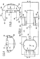
- the temperature measurement device with alert contact comprises a housing 10 made of an electrically and thermally conductive material.
- the housing 10 comprises a generally cylindrical blind internal chamber 11.
- the axis of the chamber 11 is referenced O-O.
- Chamber 11 houses a bimetallic element 20 and a heat-resistant element 150.
- the chamber 11 is closed by a cap 30 made of an electrically insulating material which also serves as a support for the contact blades 31, 32. These extend essentially parallel to the axis O-O of the housing. They pass through the cap 30. The contact blades 31, 32 are therefore accessible outside the cap. Furthermore, they emerge widely in the chamber 11 of the housing.
- the bimetallic element 20 extends along the length of the chamber 11, that is to say substantially along the axis O-O.
- a first end 21 of the bimetallic element 20 is fixed, preferably by crimping, on an electrically conductive support 40.
- This support 40 is itself immobilized against the bottom 12 of the housing, for example by crimping as illustrated at 13 in FIG. 1.
- the free end 22 of the bimetallic element 20 carries a contact grain 23 opposite the end 33 of the contact blade 32 placed in the chamber 11.
- the relative position of the bimetallic element 20 and the blade contact 32 is determined so that the state of electrical connection between the bimetallic element 20 and the contact blade 32 is changed when the temperature of the medium surrounding the housing 10 and detected by the bimetallic element 20 via the support 40 reaches an alert threshold.
- the detection of the alert temperature may correspond either to the closing of the electrical connection between the bimetallic element 20 and the contact blade 32 (this electrical connection being open when the temperature is below the alert temperature ) or at the opening of the electrical connection between the bimetallic element 20 and the contact blade 32 (this electrical connection being closed when the temperature is below the alert temperature).
- FIG. 1 the angular displacement of the bimetallic element following a rise in temperature is illustrated diagrammatically under the reference.
- the housing 10 is provided opposite the above-mentioned end 33 with a window 14.
- This window 14 allows access from the outside and after assembly of the cap 30 on the housing 10, at the end 33 of the contact blade 32 to bend it appropriately.
- the window 14 is closed after such an adjustment by a patch 15 immobilized on the housing 10 by crimping as illustrated in 16.
- cap 30 is immobilized on the housing 10 by crimping at 17 after interposition of an annular seal 18.
- the heat-resistant element 150 is carried, in association with a contact pad 160, a contact blade 170 and a spring element 180, in the form of a unitary module, by a support 100.
- a support 100 This is formed by an elongated piece of electrically insulating plastic material, for example polyamide, produced by molding.
- the part 100 has a semi-cylindrical envelope delimited by a flat base wall 101 and a semi-cylindrical wall 102, as well as two elastic tabs 103, 106. These are provided projecting from the base surface 101, substantially parallel to each other and perpendicular to said base surface 101.
- the legs 103, 106 are flush with the longitudinal free edges 109, 110, corresponding to the intersection of the base surface 101 and the semi-cylindrical surface 102.
- the external surfaces 104, 107, of the legs 103, 106 are formed of flat planes parallel to each other and perpendicular to the base surface 101.
- the free end of the legs 103, 106 is delimited by cylinder sectors 105, 108, generally having the same radius as the semi-cylindrical surface 102. It will also be noted that the radius of curvature of this semi-cylindrical surface 102 corresponds to the radius of curvature of the internal chamber 11 of the housing 10.
- the legs 103, 106 are intended to resiliently maintain the support 100 in the internal chamber 11 when the support is engaged therein.
- the heat-resistant element 150 is preferably formed of a cylindrical pellet of revolution having two flat and circular base surfaces 151, 152, forming the respective terminals of the heat-resistant element 150.
- This element is housed in a complementary cylindrical chamber 111 formed in the support 100.
- the chamber 111 opens onto the plane base surface 101. Its axis 112 is perpendicular to the plane base surface 101 and intersects the axis O-O after assembly.
- the chamber 111 also opens onto the semi-cylindrical surface 102 via an opening 113 of smaller section.
- This opening 113 is intended to receive the contact pad 160 so that it emerges outside of the support 100, as illustrated for example in FIG. 2, to come into electrical contact with the box 10 and ensure a heat exchange with this one.
- the contact pad 160 is formed by a cylindrical base 161 complementary to the chamber 111 and a projecting core 162 whose section is complementary to the opening 113.
- the height of the core 162 relative to the base 161 is determined so that when the base 161 rests against the bottom of the chamber 111, the upper surface 163 emerges on the semi-cylindrical surface 102.
- the upper surface 163 of the core 162 has a cylindrical appearance and the same radius as the internal chamber 11 of the housing 10.
- the contact blade 170 is made of an electrically conductive material, for example a copper-based alloy. It is fixed on the support 100 opposite its planar base surface 101.
- the contact blade 170 essentially comprises a straight elongated body 171 provided with a curve 172 at one end.
- the second end 173 of the contact blade 170 extends across the chamber 111.
- the contact blade 170 is fixed to the support 100 by ultrasonic welding.
- the contact blade 170 is provided with a plurality of openings 174, 175, 176 distributed over its length and receiving pins 113, 114, 115, projecting from the flat base surface 101 of the support and intended for be deformed, in a conventional manner per se, by application of ultrasound, as illustrated in FIG. 2, in order to maintain the contact blade 170.
- the curved end 172 of the contact blade 170 is intended to be placed in a blind channel 116 formed in the support 100.
- the channel 116 extends parallel to the axis OO of the housing, that is to say parallel to the axis of revolution of the semi-cylindrical surface 102. It opens onto the end of the support 100 directed towards the cap 30.
- the curved end 172 of the contact blade 170 is introduced into the channel 116 via a recess 117 connecting the channel 116 to the flat base surface 101 of the support.
- the contact blade 170 can come into electrical contact with the contact blade 31, via its curved end 172 when the cap 30 is placed on the housing 10 and thus the internal end 34 of the blade contact 31 is engaged in channel 116.
- the spring element 180 is formed by a separate piece interposed between the contact blade 170 and the flat base surface 152 of the heat-resistant element 150.
- the spring element 180 is made of an electrically conductive material, for example a copper-based alloy.
- the spring element 180 is formed of a washer having a central cutout 181 which defines a plurality of tongues 182, 183, 184, 185, generally radial, connected to the body of the washer 180 at their radially outer end and free at their radially inner end.
- the tabs 182, 183, 184, 185 are folded at their connection zone with the body of the washer 180 to take an inclined position relative to the mean plane of the washer. The position thus obtained for the tongues 182, 183, 184 and 185 is illustrated for example in FIG. 10.
- the radially internal free ends of the tongues 182 to 185 are folded a second time to form sections 186 to 189 coplanar and parallel to the body of the washer 180.
- These sections 186 to 189 coplanar make it possible to raise the contact surface between the spring element 180 and the blade contact 170 in order to improve the reliability of the electrical contact between these two elements.
- the support 40 fitted with the bimetallic element 20 is introduced into the housing 10 and immobilized against the bottom 12 of the housing by crimping 13.
- a pad 160, a heat-resistant element 150 and a spring element 180 are successively introduced into the chamber 111 of a support 100. Then a contact blade 170 is placed against the flat base face 101 of the support 100, taking care to introduce the curved end 172 into the channel 116 through the recess 117.
- the contact blade 170 is fixed on the support 100 by means of the studs 113, 114, 115, by application of ultrasound.
- the contact pad 160 rests by its base 161 against the bottom of the chamber 111.
- the heat-resistant element 150 rests by its base face 151 against the aforementioned base 161.
- the second base face 152 of the heat-resistant element 150 rests against the body of the spring element 180.
- the radially internal free end of the tongues 182 to 185 rests against the contact blade 170. Thanks to the spring element a good electrical and thermal contact is ensured between the contact pad 160 and the heat-resistant element, on the one hand, and good electrical contact is ensured between the heat-resistant element and the contact blade 170, by means of the spring 180, on the other hand.
- the support 100 thus equipped constitutes a unitary module which is easy to handle and which can be introduced into the chamber 11 of the housing, laterally next to the bimetallic element 20.
- the tabs 103, 106 flex elastically and provide centering and elastic retention of the support 100 in the housing 10.
- the contact pad 160 which emerges outside the support 100 comes to rest against the internal surface of the housing 10. The contact pad 160 therefore ensures a heat exchange between the housing 10 and the element 150 so that the latter is at the same temperature as the medium surrounding the housing 10.
- the cap 30 equipped with contact blades 31, 32 can then be placed on the housing 10 by relative translation parallel to the axis O-O. During this positioning, the internal end 34 of the contact blade 31 is engaged in the channel 116 and comes into electrical contact with the contact blade 170, more precisely the curved end 172 of the latter.
- the cap 30 is then immobilized on the body 10 by crimping 17.
- the value of the impedance of the heat-resistant element 150 representative of the temperature of the environment surrounding the housing 10 is obtained by measuring the resistance between the contact blade 31 and the housing 10.
- the housing 10 is connected to the first base face 151 of the element 150 via the contact pad 160.
- the contact blade 31 is connected to the second face 152 of the element 150 by means of the blade 170 and of the spring element 180.
- the integration of the contact pad 160 of the heat-resistant element 150, of the spring element 180 and of the blade 170 in the form of a unitary module in the support 100 greatly facilitates the assembly operations of the device.
- the arrangement of the heat-resistant element 150 in the support 100 of plastic material makes it possible to thermally isolate the heat-resistant element 150 and the bimetallic element 20. Any thermal interaction between these two elements is therefore avoided.
- the internal end 34 of the blade contact 31 comes to rest against the bottom of the channel 116 as illustrated in FIG. 1 in order to immobilize the support 100 axially in the housing 10.
- the spring element 180 can for example be integrated into the contact blade 170, or even into the contact pad 160.
- heat-resistant element is meant, within the framework of the present patent application, any element whose electrical resistance varies as a function of temperature.
Landscapes
- Physics & Mathematics (AREA)
- General Physics & Mathematics (AREA)
- Nonlinear Science (AREA)
- Thermally Actuated Switches (AREA)
- Measuring Temperature Or Quantity Of Heat (AREA)
Claims (10)
Applications Claiming Priority (2)
| Application Number | Priority Date | Filing Date | Title |
|---|---|---|---|
| FR8806214A FR2631117B1 (fr) | 1988-05-09 | 1988-05-09 | Dispositif perfectionne de mesure de temperature avec contact d'alerte |
| FR8806214 | 1988-05-09 |
Publications (2)
| Publication Number | Publication Date |
|---|---|
| EP0342112A1 EP0342112A1 (de) | 1989-11-15 |
| EP0342112B1 true EP0342112B1 (de) | 1992-01-15 |
Family
ID=9366120
Family Applications (1)
| Application Number | Title | Priority Date | Filing Date |
|---|---|---|---|
| EP89401276A Expired - Lifetime EP0342112B1 (de) | 1988-05-09 | 1989-05-05 | Temperaturmessvorrichtung mit einem Alarmschalter |
Country Status (6)
| Country | Link |
|---|---|
| US (1) | US5048974A (de) |
| EP (1) | EP0342112B1 (de) |
| AR (1) | AR240968A1 (de) |
| DE (1) | DE68900707D1 (de) |
| ES (1) | ES2028454T3 (de) |
| FR (1) | FR2631117B1 (de) |
Families Citing this family (15)
| Publication number | Priority date | Publication date | Assignee | Title |
|---|---|---|---|---|
| DE4304436A1 (de) * | 1993-02-13 | 1994-08-18 | Ego Elektro Blanc & Fischer | Überwachungseinheit für einen Leistungs-Verbraucher |
| JP3146405B2 (ja) * | 1994-04-27 | 2001-03-19 | 日本サーモスタット株式会社 | 温度センサー |
| US5574421A (en) * | 1994-09-14 | 1996-11-12 | Trig, Inc. | Snap disc thermostat and self calibrating assembly method |
| JP3820055B2 (ja) * | 1999-04-16 | 2006-09-13 | ウチヤ・サーモスタット株式会社 | サーマルプロテクタ |
| US6836205B2 (en) * | 2000-10-04 | 2004-12-28 | Honeywell International, Inc. | Thermal switch containing resistance temperature detector |
| US6707372B2 (en) * | 2000-10-04 | 2004-03-16 | Honeywell International, Inc. | Thermal switch containing preflight test feature and fault location detection |
| ITRM20010237A1 (it) * | 2001-05-04 | 2001-08-02 | Maddalo Pezzulla | Dispositivo per la rilevazione di variazioni di temperatura in un impianto elettrico alimentato da corrente continua. |
| US6737952B2 (en) * | 2001-12-04 | 2004-05-18 | Texas Instruments Incorporated | Combined pressure responsive electrical switch and temperature sensor device |
| US20050122201A1 (en) * | 2003-08-22 | 2005-06-09 | Honeywell International, Inc. | Thermal switch containing preflight test feature and fault location detection |
| US7513683B2 (en) * | 2006-10-10 | 2009-04-07 | M & Fc Holding, Llc | Method, apparatus, and system for detecting hot socket deterioration in an electrical meter connection |
| US8523432B2 (en) | 2011-02-04 | 2013-09-03 | Honeywell International Inc. | Thermally isolated temperature sensor |
| DE102011012684A1 (de) | 2011-03-01 | 2012-09-06 | Hella Kgaa Hueck & Co. | Hochtemperatursensor mit einem Sensorelement und einer Vorrichtung zum Halten und Positionieren des Sensorelementes, insbesondere für automobile Anwendungen |
| US9829365B2 (en) * | 2012-01-16 | 2017-11-28 | R.W. Beckett Corporation | Tactile feedback techniques to limit temperature runaway in boiler systems |
| FR3053784B1 (fr) * | 2016-07-07 | 2020-01-17 | Airbus Defence And Space Sas | Procedes de determination et de regulation de la temperature d’un propulseur electrique |
| CN114134039A (zh) * | 2022-01-29 | 2022-03-04 | 四川省郫县豆瓣股份有限公司 | 一种生产设备用温度报警装置 |
Family Cites Families (9)
| Publication number | Priority date | Publication date | Assignee | Title |
|---|---|---|---|---|
| FR1349369A (fr) * | 1962-12-03 | 1964-01-17 | Dispositif instantané d'épissures sur fils électriques | |
| US3295373A (en) * | 1963-01-08 | 1967-01-03 | King Seeley Thermos Co | Temperature responsive mechanism |
| US3840834A (en) * | 1972-12-18 | 1974-10-08 | Texas Instruments Inc | Protector/indicator using ptc heater and thermostatic bimetal combination |
| DE2712951A1 (de) * | 1977-03-24 | 1978-10-05 | Bosch Gmbh Robert | Bimetall mit einem elektrischen heizelement |
| DE2943922A1 (de) * | 1979-10-31 | 1981-05-14 | Ego Elektro Blanc & Fischer | Temperaturmelder zur anzeige des temperaturzustandes einer glaskeramik-kochflaeche |
| EP0049053A3 (de) * | 1980-09-03 | 1983-04-20 | Elmwood Sensors Limited | Motortemperaturfühler |
| DE3119681A1 (de) * | 1981-05-18 | 1983-01-27 | Beru-Werk Albert Ruprecht Gmbh & Co Kg, 7140 Ludwigsburg | In einen motorblock oder dergleichen einsetzbare vorrichtung zur temperaturfuehlung und/oder temperaturabhaengigen schaltung oder dergleichen |
| FR2582398B1 (fr) * | 1985-05-24 | 1987-08-21 | Jaeger | Dispositif de mesure de temperature avec contact d'alerte, en particulier pour vehicules automobiles |
| US4842419A (en) * | 1988-06-06 | 1989-06-27 | General Motors Corporation | Combination temperature sensor and switch assembly |
-
1988
- 1988-05-09 FR FR8806214A patent/FR2631117B1/fr not_active Expired - Lifetime
-
1989
- 1989-05-02 US US07/346,536 patent/US5048974A/en not_active Expired - Fee Related
- 1989-05-05 ES ES198989401276T patent/ES2028454T3/es not_active Expired - Lifetime
- 1989-05-05 DE DE8989401276T patent/DE68900707D1/de not_active Expired - Fee Related
- 1989-05-05 EP EP89401276A patent/EP0342112B1/de not_active Expired - Lifetime
- 1989-05-05 AR AR313854A patent/AR240968A1/es active
Also Published As
| Publication number | Publication date |
|---|---|
| FR2631117A1 (fr) | 1989-11-10 |
| AR240968A2 (es) | 1991-03-27 |
| EP0342112A1 (de) | 1989-11-15 |
| AR240968A1 (es) | 1991-03-27 |
| FR2631117B1 (fr) | 1991-04-12 |
| ES2028454T3 (es) | 1992-07-01 |
| DE68900707D1 (de) | 1992-02-27 |
| US5048974A (en) | 1991-09-17 |
Similar Documents
| Publication | Publication Date | Title |
|---|---|---|
| EP0342112B1 (de) | Temperaturmessvorrichtung mit einem Alarmschalter | |
| FR2935449A1 (fr) | Unite de montage de capteur de temperature | |
| FR2492742A1 (fr) | Capteur de pression pour pneumatiques | |
| FR2943149A1 (fr) | Cartouche chauffante et element thermostatique comportant une telle cartouche. | |
| FR2663703A1 (fr) | Capteur d'usure de plaquette de frein pour vehicules automobiles. | |
| FR2723202A1 (fr) | Capteur de grandeur physique, notamment un capteurde temperature | |
| EP0203858A1 (de) | Temperaturmessvorrichtung mit Alarmschalter, insbesondere für Kraftwagen | |
| FR2629587A1 (fr) | Transducteur de type perfectionne | |
| EP1087685B1 (de) | Elektrisches gargerät mit herausnehmbarer wanne | |
| FR2660431A1 (fr) | Capteur de temperature a thermistance. | |
| FR2890780A1 (fr) | Contacteur de demarreur de moteur thermique comportant des moyens perfectionnes de raccordement electrique de son bobinage | |
| EP0391798A1 (de) | Temperatursensor mit Thermistor und Verfahren zur dessen Herstellung | |
| EP3450617A1 (de) | Bügelvorrichtung umfassend eine basis verbunden mittels eines kabels mit einem bügeleisen | |
| EP3450619A1 (de) | Bügeleisen, das ein gehäuse, einen heizkörper und eine zwischen dem heizkörper und dem gehäuse eingebaute funktionelle platine umfasst | |
| EP0562970A1 (de) | Zusammenbau eines Ringkernes mit Spule | |
| FR2674953A1 (fr) | Dispositif de mesure de niveau de liquide a sonde resistive plongee dans le liquide. | |
| EP3450618A1 (de) | Bügeleisen mit einem elektrischen widerstand und einer sicherung zum trennen der stromversorgung des elektrischen widerstands | |
| FR2707004A1 (en) | Device for measuring the level of a liquid, in particlar oil, with a resistive probe | |
| FR2495553A1 (fr) | Allume-cigare electrique pour vehicule automobile | |
| EP0447301B1 (de) | Temperaturmessgerät, insbesondere für die Temperaturüberwachung in Automobilmotoren | |
| FR2702604A1 (fr) | Dispositif injecteur pour la jonction et le tamponnement de câbles électriques ou pour télécommunications. | |
| FR2488032A1 (fr) | Thermostat, notamment pour vannes melangeuses d'installations sanitaires | |
| FR2793557A1 (fr) | Capteur de temperature, notamment pour la mesure dand un alesage borgne de carter de moteur de vehicule automobile | |
| WO2019115749A1 (fr) | Cartouche chauffante pour un élément thermostatique, ainsi que vanne thermostatique comportant une telle cartouche | |
| EP1727241A2 (de) | Verbindung einer Batterieanschlußklemme und einer Sonde, insbesondere thermisch |
Legal Events
| Date | Code | Title | Description |
|---|---|---|---|
| PUAI | Public reference made under article 153(3) epc to a published international application that has entered the european phase |
Free format text: ORIGINAL CODE: 0009012 |
|
| AK | Designated contracting states |
Kind code of ref document: A1 Designated state(s): DE ES GB IT |
|
| 17P | Request for examination filed |
Effective date: 19900122 |
|
| 17Q | First examination report despatched |
Effective date: 19910426 |
|
| GRAA | (expected) grant |
Free format text: ORIGINAL CODE: 0009210 |
|
| AK | Designated contracting states |
Kind code of ref document: B1 Designated state(s): DE ES GB IT |
|
| REF | Corresponds to: |
Ref document number: 68900707 Country of ref document: DE Date of ref document: 19920227 |
|
| GBT | Gb: translation of ep patent filed (gb section 77(6)(a)/1977) | ||
| ITF | It: translation for a ep patent filed |
Owner name: SOCIETA' ITALIANA BREVETTI S.P.A. |
|
| REG | Reference to a national code |
Ref country code: ES Ref legal event code: FG2A Ref document number: 2028454 Country of ref document: ES Kind code of ref document: T3 |
|
| PLBE | No opposition filed within time limit |
Free format text: ORIGINAL CODE: 0009261 |
|
| STAA | Information on the status of an ep patent application or granted ep patent |
Free format text: STATUS: NO OPPOSITION FILED WITHIN TIME LIMIT |
|
| 26N | No opposition filed | ||
| PGFP | Annual fee paid to national office [announced via postgrant information from national office to epo] |
Ref country code: GB Payment date: 20010427 Year of fee payment: 13 |
|
| PGFP | Annual fee paid to national office [announced via postgrant information from national office to epo] |
Ref country code: DE Payment date: 20010511 Year of fee payment: 13 |
|
| PGFP | Annual fee paid to national office [announced via postgrant information from national office to epo] |
Ref country code: ES Payment date: 20010521 Year of fee payment: 13 |
|
| REG | Reference to a national code |
Ref country code: GB Ref legal event code: IF02 |
|
| PG25 | Lapsed in a contracting state [announced via postgrant information from national office to epo] |
Ref country code: GB Free format text: LAPSE BECAUSE OF NON-PAYMENT OF DUE FEES Effective date: 20020505 |
|
| PG25 | Lapsed in a contracting state [announced via postgrant information from national office to epo] |
Ref country code: ES Free format text: LAPSE BECAUSE OF NON-PAYMENT OF DUE FEES Effective date: 20020506 |
|
| PG25 | Lapsed in a contracting state [announced via postgrant information from national office to epo] |
Ref country code: DE Free format text: LAPSE BECAUSE OF NON-PAYMENT OF DUE FEES Effective date: 20021203 |
|
| GBPC | Gb: european patent ceased through non-payment of renewal fee |
Effective date: 20020505 |
|
| REG | Reference to a national code |
Ref country code: ES Ref legal event code: FD2A Effective date: 20030611 |
|
| PG25 | Lapsed in a contracting state [announced via postgrant information from national office to epo] |
Ref country code: IT Free format text: LAPSE BECAUSE OF NON-PAYMENT OF DUE FEES Effective date: 20050505 |