EP0341980A2 - Verfahren und Schaltung zur Spannungsregelung für Gleichspannungsquellen, die einen Generator mit Erregerwicklung beinhalten - Google Patents
Verfahren und Schaltung zur Spannungsregelung für Gleichspannungsquellen, die einen Generator mit Erregerwicklung beinhalten Download PDFInfo
- Publication number
- EP0341980A2 EP0341980A2 EP89304679A EP89304679A EP0341980A2 EP 0341980 A2 EP0341980 A2 EP 0341980A2 EP 89304679 A EP89304679 A EP 89304679A EP 89304679 A EP89304679 A EP 89304679A EP 0341980 A2 EP0341980 A2 EP 0341980A2
- Authority
- EP
- European Patent Office
- Prior art keywords
- signal
- generator
- voltage
- produce
- output voltage
- Prior art date
- Legal status (The legal status is an assumption and is not a legal conclusion. Google has not performed a legal analysis and makes no representation as to the accuracy of the status listed.)
- Granted
Links
Images

Classifications
-
- H—ELECTRICITY
- H02—GENERATION; CONVERSION OR DISTRIBUTION OF ELECTRIC POWER
- H02J—CIRCUIT ARRANGEMENTS OR SYSTEMS FOR SUPPLYING OR DISTRIBUTING ELECTRIC POWER; SYSTEMS FOR STORING ELECTRIC ENERGY
- H02J3/00—Circuit arrangements for AC mains or AC distribution networks
- H02J3/12—Circuit arrangements for AC mains or AC distribution networks for adjusting voltage in AC networks by changing a characteristic of the network load
-
- H—ELECTRICITY
- H02—GENERATION; CONVERSION OR DISTRIBUTION OF ELECTRIC POWER
- H02P—CONTROL OR REGULATION OF ELECTRIC MOTORS, ELECTRIC GENERATORS OR DYNAMO-ELECTRIC CONVERTERS; CONTROLLING TRANSFORMERS, REACTORS OR CHOKE COILS
- H02P9/00—Arrangements for controlling electric generators for the purpose of obtaining a desired output
- H02P9/14—Arrangements for controlling electric generators for the purpose of obtaining a desired output by variation of field
- H02P9/26—Arrangements for controlling electric generators for the purpose of obtaining a desired output by variation of field using discharge tubes or semiconductor devices
- H02P9/30—Arrangements for controlling electric generators for the purpose of obtaining a desired output by variation of field using discharge tubes or semiconductor devices using semiconductor devices
- H02P9/305—Arrangements for controlling electric generators for the purpose of obtaining a desired output by variation of field using discharge tubes or semiconductor devices using semiconductor devices controlling voltage
-
- H—ELECTRICITY
- H02—GENERATION; CONVERSION OR DISTRIBUTION OF ELECTRIC POWER
- H02J—CIRCUIT ARRANGEMENTS OR SYSTEMS FOR SUPPLYING OR DISTRIBUTING ELECTRIC POWER; SYSTEMS FOR STORING ELECTRIC ENERGY
- H02J7/00—Circuit arrangements for charging or depolarising batteries or for supplying loads from batteries
- H02J7/14—Circuit arrangements for charging or depolarising batteries or for supplying loads from batteries for charging batteries from dynamo-electric generators driven at varying speed, e.g. on vehicle
- H02J7/16—Regulation of the charging current or voltage by variation of field
- H02J7/24—Regulation of the charging current or voltage by variation of field using discharge tubes or semiconductor devices
-
- H—ELECTRICITY
- H02—GENERATION; CONVERSION OR DISTRIBUTION OF ELECTRIC POWER
- H02P—CONTROL OR REGULATION OF ELECTRIC MOTORS, ELECTRIC GENERATORS OR DYNAMO-ELECTRIC CONVERTERS; CONTROLLING TRANSFORMERS, REACTORS OR CHOKE COILS
- H02P2101/00—Special adaptation of control arrangements for generators
- H02P2101/30—Special adaptation of control arrangements for generators for aircraft
Definitions
- This invention relates to regulation of the output voltage of electrical power sources and, more particularly to the regulation of DC electrical power sources which include a generator having an exciter field coil with the output of the generator being proportional to current in the exciter field coil.
- DC electrical power systems offer several advantages over AC systems in aerospace applications.
- DC systems eliminate reactive voltage drops in feeder lines at high power levels and are compatible with electromechanical actuators.
- DC power may be developed by a wide speed range generator and simple rectifier thereby eliminating the constant speed drive or converter required for constant frequency AC systems.
- off line power conversion components and circuits can operate directly from relatively high voltage DC with very high frequency converters replacing 400 hertz transformers and rectifiers.
- a typical 270 volts DC aircraft generating system includes a wide speed range generator having a multiple phase AC output which is rectified by a full wave bridge rectifier and filtered by a capacitor to produce the DC output.
- a voltage regulator senses the DC output voltage and controls the excitation of the generator to maintain the output voltage.
- the time constant of the output filter capacitor and load resistance can vary over several orders of magnitude as the load is changed.
- the output capacitor has no discharge path at all.
- a load removal transient on the system will naturally cause an overshoot in the output voltage.
- the overshoot voltage becomes trapped on the filter capacitor which holds the output high for a time dependent only on leakage currents.
- the regulator senses DC output voltage and the bridge rectifier is not conducting, the regulation control loop is broken. Under those conditions, the voltage regulator senses the high output voltage and reduces the generator excitation to zero, attempting to reduce the overshoot. In effect, the generator goes to sleep.
- the generator AC output will not start to increase until the DC output falls below the regulation set point.
- the regulator begins to increase excitation to the generator.
- Excitation current can only increase at a rate limited by the forcing voltage and inductance of the exciter field winding. As generator output increases, it will overshoot the regulation point again and a limit cycle may result.
- Time constants in the regulator may be chosen to eliminate the limit cycle but only at the expense of good load transient response. Even a very slow responding system will still have the sleeping generator problem at no load.
- a bleeder resister may be added across the DC output to bring the output voltage down more quickly, but at the expense of efficiency.
- the required bleeder current may be several percent of the rated output current.
- a bleeder current of 2% will cause a 2% loss in efficiency, more than doubling the losses in the rectifier.
- This invention provides a method for regulating a DC electrical power source having a generator, with an exciter field coil, that produces an AC output voltage which is rectified to produce a DC output voltage.
- the method includes the steps of: producing a first signal proportional to the AC output voltage of the generator; sensing the current in the exciter field winding of the generator; producing a second signal proportional to the exciter field current; and combining the first and second signals to produce a third signal.
- a fourth signal proportional to the DC output voltage of the power source is compared to a DC reference signal to produce a trim error signal.
- the trim error signal is combined with an AC reference signal to produce a fifth signal.
- the third and fifth signals are compared to produce a sixth signal and the current in the exciter field winding is controlled in response to this sixth signal.
- the various signals are voltage signals.
- This invention also encompasses a circuit which performs the above voltage regulation method.
- this invention is capable of limiting a resulting overvoltage condition to tolerable voltages in the event of a loss of the DC sensing conductors.
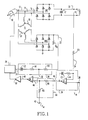
- FIG. 1 is a schematic diagram of a DC electrical power system having a voltage regulator constructed in accordance with one embodiment of the present invention.
- Generator 10 is a wide speed range generator, such as typically found on aircraft, and produces a three-phase AC output voltage on conductors 12, 14 and 16. This AC voltage is rectified by full wave bridge rectifier BR1 and filtered by capacitor C1 to produce a DC output voltage for a load indicated by resistor R L .
- a WYE-WYE connected sensing transformer T1 includes a multiple phase primary winding 18 connected to the three-phase output of the generator and a secondary winding 20 connected to a full wave bridge rectifier BR2 to produce a first voltage signal proportional to the AC output voltage of the generator on line 22.
- bridge BR1 If bridge BR1 is conducting, the voltage signal on line 22 will be proportional to the DC output. If bridge BR1 is not conducting, due to an output voltage overshoot, the voltage signal on line 22 will follow the generator output.
- the WYE-WYE winding configuration of transformer T1 ensures that the first voltage signal will track a DC output for any wave shape or distortion in the output of the generator. In other words, the first voltage signal developed by bridge BR2 will match the output of bridge BR1 whenever bridge BR1 is conducting.
- a second, or feedback, voltage signal proportional to the exciter field current is produced on line 24 by current sensor 26.
- a divider circuit 28 comprising capacitor C2 and resistors R1 and R2 is used to combine the first and second voltage signals on lines 22 and 24 to produce a third voltage signal on line 30. Because there is no filter capacitor on the output of bridge BR2, the first voltage signal on line 22 always follows the generator output voltage. The control loop is not broken when bridge BR1 stops conducting. Transient response of the AC control loop can be optimized without regard for the output filter discharge time constant at light loads. Because the DC output voltage across capacitor C1 is filtered and the first voltage signal on line 22 is not filtered, tracking between the two will vary as the DC output is loaded. For example, at very light leads, the DC output will ride up to the peak of the generator AC output. At heavy loads, the DC output will be about 5% lower.
- Resister R3 is connected to sense the DC output voltage on line 32 to produce a fourth voltage control signal, which is proportional to the DC output voltage of the power source, on line 34.
- a comparator circuit 36 including operational amplifier U1, resistor R4 and capacitor C3, compares the fourth voltage signal on line 34 to a first, or DC, reference voltage signal supplied on terminal 38. This produces a trim error voltage signal on line 40.
- the trim error signal is proportional to the error plus the integral of the error signal which is used to trim a second, or AC, reference voltage signal supplied on terminal 42.
- both the DC and AC reference voltage signals are actually DC signals with the magnitudes being proportional to desired levels of DC and AC voltage respectively.
- This trimming is accomplished by supplying the trim error voltage signal and AC reference voltage signal to opposite ends of a voltage divider 44 which comprises resistors R5 and R6. By using voltage divider 44 to combine the trim error voltage signal and AC reference voltage signals, a fifth voltage signal is produced on line 46.
- Comparator U2 compares the third voltage signal on line 30 with the fifth voltage signal on line 46 to produce a pulse width modulated sixth voltage signal on line 48.
- Power amplifier 50 then controls the current in the generator exciter field winding in response to this sixth voltage signal.
- the trim error signal trims the fourth voltage control signal to match the DC reference exactly, despite loading of the system. This is due to the integrating nature of the error amplifier and capacitor C3. The integrator thus provides infinite loop gain for the trim loop, and the final steady state voltage on line 32 will match the DC reference for all loads.
- the range of the trim error voltage signal is limited to compensate only for loading and temperature effects. This range is limited by the saturation of operational amplifier U1 and the choice of values for resistors R5 and R6. As a result, the generator output is maintained close to the proper voltage, even when a load removal transient has produced an over voltage output. If the trim range is limited to, for example, 10%, then the generator output will be maintained at 90% of the proper output voltage until capacitor C1 discharges and bridge BR1 begins to conduct. Load applications will be supported by the generator waiting at 90% voltage. Thus the problem of the sleeping generator is reduced considerably.
- the response time of the DC trim loop is set so as to not interfere with the AC loop. This is done by making its response somewhat slower than that of the AC loop.
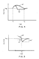
- Figures 2 and 3 illustrate the operation of prior art voltage regulation schemes wherein regulation is responsive to the DC output voltage of the power source.
- Curve 52 represents the DC output voltage of the system and curve 54 represents the AC output voltage of the generator.
- the system is operating under stable conditions at the regulated output voltage, V reg when at time T1 the load is suddenly removed and the output voltage and generator voltage begin to overshoot the regulated values. Since the regulation control loop is broken, the regulator senses the high output voltage and reduces the generator excitation to zero, attempting to reduce the overshoot.
- FIG. 3 illustrates the operation of the same prior art voltage regulation technique when the load is suddenly reapplied while the generator is asleep. This occurs at time T4 and the only source of output power is the output filter capacitor. This results in the output voltage being severely depressed by an amount V1 while the generator output is increasing.
- Figures 4 and 5 illustrate the operation of the present invention.
- curve 52′ represents the DC output voltage
- curve 54′ represents the generator AC output voltage.
- Figure 4 illustrates the performance of the system when the load is suddenly removed at time T1′. Once again, the DC output voltage and AC output voltages overshoot. However, the present invention prevents the AC output voltage of the generator from falling below about 90% of its normal magnitude. Therefore, when the DC output voltage falls below the regulation setpoint at time T3′, the voltage transient created when the generator output again increases to its normal value is considerably reduced.
- Figure 5 illustrates the operation of this invention when the load is suddenly reapplied at time T4′ following a temporarily output voltage overshoot. In this case, the transient voltage V1′ is seen to be significantly smaller than the transient voltage V1 in Figure 3.
Landscapes
- Engineering & Computer Science (AREA)
- Power Engineering (AREA)
- Control Of Eletrric Generators (AREA)
- Rectifiers (AREA)
Applications Claiming Priority (2)
| Application Number | Priority Date | Filing Date | Title |
|---|---|---|---|
| US193870 | 1988-05-12 | ||
| US07/193,870 US4807106A (en) | 1988-05-12 | 1988-05-12 | Method and circuit for voltage regulation of DC power sources |
Publications (3)
| Publication Number | Publication Date |
|---|---|
| EP0341980A2 true EP0341980A2 (de) | 1989-11-15 |
| EP0341980A3 EP0341980A3 (de) | 1991-01-02 |
| EP0341980B1 EP0341980B1 (de) | 1993-09-29 |
Family
ID=22715346
Family Applications (1)
| Application Number | Title | Priority Date | Filing Date |
|---|---|---|---|
| EP89304679A Expired - Lifetime EP0341980B1 (de) | 1988-05-12 | 1989-05-09 | Verfahren und Schaltung zur Spannungsregelung für Gleichspannungsquellen, die einen Generator mit Erregerwicklung beinhalten |
Country Status (6)
| Country | Link |
|---|---|
| US (1) | US4807106A (de) |
| EP (1) | EP0341980B1 (de) |
| JP (1) | JPH0213298A (de) |
| KR (1) | KR890017838A (de) |
| CN (1) | CN1019069B (de) |
| DE (1) | DE68909489T2 (de) |
Cited By (1)
| Publication number | Priority date | Publication date | Assignee | Title |
|---|---|---|---|---|
| EP0448065A1 (de) * | 1990-03-22 | 1991-09-25 | MAGNETI MARELLI S.p.A. | Vorrichtung zur Nachladung einer Batterie in einem Fahrzeug |
Families Citing this family (21)
| Publication number | Priority date | Publication date | Assignee | Title |
|---|---|---|---|---|
| FR2642580B1 (fr) * | 1989-01-11 | 1991-05-17 | Equip Electr Moteur | Regulateur plurifonction a cadencement synchrone de l'alternateur |
| US4933622A (en) * | 1988-12-29 | 1990-06-12 | Westinghouse Electric Corp. | Circuit and method for discharging DC filter capacitors |
| US4970458A (en) * | 1989-05-08 | 1990-11-13 | Westinghouse Electric Corp. | AC voltage sensing for voltage regulators |
| US5117174A (en) * | 1989-10-03 | 1992-05-26 | Westinghouse Electric Corp. | Electric power system with line drop compensation |
| US5038094A (en) * | 1989-12-04 | 1991-08-06 | Sundstrand Corporation | Reference trimming for a digital voltage regulator |
| DE4200329C2 (de) * | 1992-01-09 | 1994-12-22 | Gutehoffnungshuette Man | Regelbare Speisestromquelle |
| JP3393617B2 (ja) * | 1994-03-09 | 2003-04-07 | 勲 高橋 | 三相正弦波入力スイッチング電源回路 |
| US5554923A (en) * | 1995-06-01 | 1996-09-10 | Sundstrand Corporation | Voltage regulator and method for DC power generating system |
| US5694310A (en) * | 1995-08-14 | 1997-12-02 | International Business Machines Corporation | Three phase input boost converter |
| JP2000050696A (ja) * | 1998-08-03 | 2000-02-18 | Sawafuji Electric Co Ltd | 発動発電機用自動電圧調整装置 |
| FR2835106B1 (fr) * | 2002-01-24 | 2004-09-03 | Peugeot Citroen Automobiles Sa | Systeme d'alimentation en energie electrique d'un vehicule automobile |
| US7196498B2 (en) * | 2004-09-08 | 2007-03-27 | Honeywell International Inc. | Method and apparatus for generator control |
| JP4720268B2 (ja) * | 2005-04-15 | 2011-07-13 | カシオ計算機株式会社 | 時計装置およびその時刻合わせ処理プログラム |
| JP2007209078A (ja) | 2006-01-31 | 2007-08-16 | Mitsubishi Electric Corp | 車両用交流発電機 |
| US7582978B2 (en) * | 2006-11-17 | 2009-09-01 | Kohler Co. | Auxiliary power unit for a motor vehicle |
| CN104660131B (zh) * | 2015-03-03 | 2017-03-01 | 河海大学常州校区 | 一种利用混合励磁直流发电机电压调节装置的调节方法 |
| CN108073294B (zh) * | 2016-11-11 | 2021-11-02 | 北京搜狗科技发展有限公司 | 一种智能组词方法和装置、一种用于智能组词的装置 |
| CN109213777A (zh) * | 2017-06-29 | 2019-01-15 | 杭州九阳小家电有限公司 | 一种基于语音的食谱处理方法及系统 |
| CN109149962B (zh) * | 2018-09-03 | 2020-09-08 | 中国商用飞机有限责任公司北京民用飞机技术研究中心 | 基于电压参考信号补偿直流供电系统稳定性的方法和装置 |
| CN109067279B (zh) * | 2018-09-03 | 2020-11-17 | 中国商用飞机有限责任公司北京民用飞机技术研究中心 | 基于电流参考信号补偿直流供电系统稳定性的装置及方法 |
| CN113937806B (zh) * | 2020-09-17 | 2023-09-29 | 华北电力大学(保定) | 一种抑制风光水经直流外送系统送端过电压的方法 |
Family Cites Families (7)
| Publication number | Priority date | Publication date | Assignee | Title |
|---|---|---|---|---|
| US3072840A (en) * | 1961-07-27 | 1963-01-08 | Gen Motors Corp | Regulating system for alternators |
| US3668514A (en) * | 1970-09-15 | 1972-06-06 | Oaks Power Corp | Dual voltage power system for use with vehicle alternators and the like |
| US4030017A (en) * | 1975-02-03 | 1977-06-14 | Lorain Products Corporation | Controlled reactance regulator circuit |
| US3996507A (en) * | 1975-08-27 | 1976-12-07 | General Electric Company | Regulator for controlling synchronous dynamoelectric machines |
| US4446417A (en) * | 1982-02-12 | 1984-05-01 | Westinghouse Electric Corp. | Voltage regulator for aircraft generators |
| US4658200A (en) * | 1983-03-25 | 1987-04-14 | Mitsubishi Denki Kabushiki Kaisha | Protection circuit for voltage regulator of vehicle mounted generator |
| US4622629A (en) * | 1984-10-12 | 1986-11-11 | Sundstrand Corporation | Power supply system with improved transient response |
-
1988
- 1988-05-12 US US07/193,870 patent/US4807106A/en not_active Expired - Fee Related
-
1989
- 1989-05-09 EP EP89304679A patent/EP0341980B1/de not_active Expired - Lifetime
- 1989-05-09 DE DE89304679T patent/DE68909489T2/de not_active Expired - Fee Related
- 1989-05-12 JP JP1120195A patent/JPH0213298A/ja active Pending
- 1989-05-12 CN CN89103170A patent/CN1019069B/zh not_active Expired
- 1989-05-13 KR KR1019890006420A patent/KR890017838A/ko not_active Withdrawn
Cited By (1)
| Publication number | Priority date | Publication date | Assignee | Title |
|---|---|---|---|---|
| EP0448065A1 (de) * | 1990-03-22 | 1991-09-25 | MAGNETI MARELLI S.p.A. | Vorrichtung zur Nachladung einer Batterie in einem Fahrzeug |
Also Published As
| Publication number | Publication date |
|---|---|
| EP0341980B1 (de) | 1993-09-29 |
| CN1038555A (zh) | 1990-01-03 |
| DE68909489D1 (de) | 1993-11-04 |
| US4807106A (en) | 1989-02-21 |
| JPH0213298A (ja) | 1990-01-17 |
| KR890017838A (ko) | 1989-12-18 |
| CN1019069B (zh) | 1992-11-11 |
| DE68909489T2 (de) | 1994-02-24 |
| EP0341980A3 (de) | 1991-01-02 |
Similar Documents
| Publication | Publication Date | Title |
|---|---|---|
| EP0341980B1 (de) | Verfahren und Schaltung zur Spannungsregelung für Gleichspannungsquellen, die einen Generator mit Erregerwicklung beinhalten | |
| US5724237A (en) | Apparatus and method for sharing a load current among frequency-controlled D.C.-to-D.C. converters | |
| EP0157282B1 (de) | Elektrische Speiseschaltung welche einen Abfall elektrischer Leistung vermindern kann | |
| US4044296A (en) | Electronic voltage regulator for three-phase generators | |
| US4622629A (en) | Power supply system with improved transient response | |
| US4862339A (en) | DC power supply with improved output stabilizing feedback | |
| US4608499A (en) | Power system and power generation method | |
| CN1050800A (zh) | 带有线路降压补偿的电力系统 | |
| US20030085691A1 (en) | Control system for regulating exciter power for a brushless synchronous generator | |
| JPS5884323A (ja) | 複数出力dc−dc変換器の出力回路の負荷電圧を安定化する方法及びその装置 | |
| US4262242A (en) | Voltage regulator | |
| JPH01222659A (ja) | 電流バランス型スイッチングレギュレータ | |
| EP0540716A1 (de) | System zur erzeugung von energie mit transientenunterdrückung | |
| EP0376728A2 (de) | Schaltung und Verfahren zur Spannungsregelung von elektrischen Stromquellen | |
| EP1704636B1 (de) | Vorrichtung und verfahren zur regulierung variabler wechselspannung | |
| US4352055A (en) | AC Variable voltage source utilizing pulse width modulation | |
| US4868481A (en) | Apparatus and method for balancing electrical currents in a multiple-phase system | |
| US4933622A (en) | Circuit and method for discharging DC filter capacitors | |
| US4225911A (en) | Apparatus and method for reducing overvoltage transients on the outputs of a VSCF system | |
| US4697135A (en) | Electronic voltage regulator | |
| CA1115344A (en) | Voltage regulator for a.c. generator | |
| CA1249023A (en) | Apparatus for auxiliary power supply from a generator field | |
| CA2005092A1 (en) | Generator voltage regulation with non-linear compensation | |
| WO1994013057A1 (en) | Power converter circuit | |
| JPH1080199A (ja) | 同期発電機の自動電圧調整器 |
Legal Events
| Date | Code | Title | Description |
|---|---|---|---|
| PUAI | Public reference made under article 153(3) epc to a published international application that has entered the european phase |
Free format text: ORIGINAL CODE: 0009012 |
|
| AK | Designated contracting states |
Kind code of ref document: A2 Designated state(s): DE FR |
|
| PUAL | Search report despatched |
Free format text: ORIGINAL CODE: 0009013 |
|
| AK | Designated contracting states |
Kind code of ref document: A3 Designated state(s): DE FR |
|
| 17P | Request for examination filed |
Effective date: 19910628 |
|
| RAP1 | Party data changed (applicant data changed or rights of an application transferred) |
Owner name: SUNDSTRAND CORPORATION |
|
| 17Q | First examination report despatched |
Effective date: 19930129 |
|
| GRAA | (expected) grant |
Free format text: ORIGINAL CODE: 0009210 |
|
| AK | Designated contracting states |
Kind code of ref document: B1 Designated state(s): DE FR |
|
| REF | Corresponds to: |
Ref document number: 68909489 Country of ref document: DE Date of ref document: 19931104 |
|
| ET | Fr: translation filed | ||
| PGFP | Annual fee paid to national office [announced via postgrant information from national office to epo] |
Ref country code: FR Payment date: 19940413 Year of fee payment: 6 |
|
| PGFP | Annual fee paid to national office [announced via postgrant information from national office to epo] |
Ref country code: DE Payment date: 19940414 Year of fee payment: 6 |
|
| PLBE | No opposition filed within time limit |
Free format text: ORIGINAL CODE: 0009261 |
|
| STAA | Information on the status of an ep patent application or granted ep patent |
Free format text: STATUS: NO OPPOSITION FILED WITHIN TIME LIMIT |
|
| 26N | No opposition filed | ||
| PG25 | Lapsed in a contracting state [announced via postgrant information from national office to epo] |
Ref country code: DE Effective date: 19960201 |
|
| PG25 | Lapsed in a contracting state [announced via postgrant information from national office to epo] |
Ref country code: FR Effective date: 19960229 |
|
| REG | Reference to a national code |
Ref country code: FR Ref legal event code: ST |
|
| REG | Reference to a national code |
Ref country code: FR Ref legal event code: ST |