EP0341942B1 - Schneiden von spröden Materialien - Google Patents
Schneiden von spröden Materialien Download PDFInfo
- Publication number
- EP0341942B1 EP0341942B1 EP89304600A EP89304600A EP0341942B1 EP 0341942 B1 EP0341942 B1 EP 0341942B1 EP 89304600 A EP89304600 A EP 89304600A EP 89304600 A EP89304600 A EP 89304600A EP 0341942 B1 EP0341942 B1 EP 0341942B1
- Authority
- EP
- European Patent Office
- Prior art keywords
- workpiece
- tool
- tip
- stress
- vibrations
- Prior art date
- Legal status (The legal status is an assumption and is not a legal conclusion. Google has not performed a legal analysis and makes no representation as to the accuracy of the status listed.)
- Expired - Lifetime
Links
- 239000000463 material Substances 0.000 title claims abstract description 22
- 238000000034 method Methods 0.000 claims abstract description 21
- 239000000919 ceramic Substances 0.000 claims description 8
- 238000005452 bending Methods 0.000 claims description 5
- UONOETXJSWQNOL-UHFFFAOYSA-N tungsten carbide Chemical compound [W+]#[C-] UONOETXJSWQNOL-UHFFFAOYSA-N 0.000 claims description 3
- 125000004122 cyclic group Chemical group 0.000 abstract description 5
- 230000003534 oscillatory effect Effects 0.000 abstract description 2
- 238000000926 separation method Methods 0.000 abstract description 2
- 229910001220 stainless steel Inorganic materials 0.000 description 2
- 239000010935 stainless steel Substances 0.000 description 2
- 239000005341 toughened glass Substances 0.000 description 2
- 239000002131 composite material Substances 0.000 description 1
- 238000010276 construction Methods 0.000 description 1
- 229910003460 diamond Inorganic materials 0.000 description 1
- 239000010432 diamond Substances 0.000 description 1
- 230000000694 effects Effects 0.000 description 1
- 230000005284 excitation Effects 0.000 description 1
- 239000005329 float glass Substances 0.000 description 1
- 238000009408 flooring Methods 0.000 description 1
- 239000011521 glass Substances 0.000 description 1
- 238000003754 machining Methods 0.000 description 1
- 239000004579 marble Substances 0.000 description 1
- 230000008092 positive effect Effects 0.000 description 1
- 239000007779 soft material Substances 0.000 description 1
- 230000002459 sustained effect Effects 0.000 description 1
Images


Classifications
-
- B—PERFORMING OPERATIONS; TRANSPORTING
- B26—HAND CUTTING TOOLS; CUTTING; SEVERING
- B26D—CUTTING; DETAILS COMMON TO MACHINES FOR PERFORATING, PUNCHING, CUTTING-OUT, STAMPING-OUT OR SEVERING
- B26D7/00—Details of apparatus for cutting, cutting-out, stamping-out, punching, perforating, or severing by means other than cutting
- B26D7/08—Means for treating work or cutting member to facilitate cutting
- B26D7/086—Means for treating work or cutting member to facilitate cutting by vibrating, e.g. ultrasonically
-
- B—PERFORMING OPERATIONS; TRANSPORTING
- B06—GENERATING OR TRANSMITTING MECHANICAL VIBRATIONS IN GENERAL
- B06B—METHODS OR APPARATUS FOR GENERATING OR TRANSMITTING MECHANICAL VIBRATIONS OF INFRASONIC, SONIC, OR ULTRASONIC FREQUENCY, e.g. FOR PERFORMING MECHANICAL WORK IN GENERAL
- B06B3/00—Methods or apparatus specially adapted for transmitting mechanical vibrations of infrasonic, sonic, or ultrasonic frequency
-
- B—PERFORMING OPERATIONS; TRANSPORTING
- B28—WORKING CEMENT, CLAY, OR STONE
- B28D—WORKING STONE OR STONE-LIKE MATERIALS
- B28D1/00—Working stone or stone-like materials, e.g. brick, concrete or glass, not provided for elsewhere; Machines, devices, tools therefor
- B28D1/26—Working stone or stone-like materials, e.g. brick, concrete or glass, not provided for elsewhere; Machines, devices, tools therefor by impact tools, e.g. by chisels or other tools having a cutting edge
-
- B—PERFORMING OPERATIONS; TRANSPORTING
- B28—WORKING CEMENT, CLAY, OR STONE
- B28D—WORKING STONE OR STONE-LIKE MATERIALS
- B28D5/00—Fine working of gems, jewels, crystals, e.g. of semiconductor material; apparatus or devices therefor
- B28D5/04—Fine working of gems, jewels, crystals, e.g. of semiconductor material; apparatus or devices therefor by tools other than rotary type, e.g. reciprocating tools
- B28D5/047—Fine working of gems, jewels, crystals, e.g. of semiconductor material; apparatus or devices therefor by tools other than rotary type, e.g. reciprocating tools by ultrasonic cutting
-
- Y—GENERAL TAGGING OF NEW TECHNOLOGICAL DEVELOPMENTS; GENERAL TAGGING OF CROSS-SECTIONAL TECHNOLOGIES SPANNING OVER SEVERAL SECTIONS OF THE IPC; TECHNICAL SUBJECTS COVERED BY FORMER USPC CROSS-REFERENCE ART COLLECTIONS [XRACs] AND DIGESTS
- Y10—TECHNICAL SUBJECTS COVERED BY FORMER USPC
- Y10S—TECHNICAL SUBJECTS COVERED BY FORMER USPC CROSS-REFERENCE ART COLLECTIONS [XRACs] AND DIGESTS
- Y10S83/00—Cutting
- Y10S83/956—Ultrasonic
-
- Y—GENERAL TAGGING OF NEW TECHNOLOGICAL DEVELOPMENTS; GENERAL TAGGING OF CROSS-SECTIONAL TECHNOLOGIES SPANNING OVER SEVERAL SECTIONS OF THE IPC; TECHNICAL SUBJECTS COVERED BY FORMER USPC CROSS-REFERENCE ART COLLECTIONS [XRACs] AND DIGESTS
- Y10—TECHNICAL SUBJECTS COVERED BY FORMER USPC
- Y10T—TECHNICAL SUBJECTS COVERED BY FORMER US CLASSIFICATION
- Y10T225/00—Severing by tearing or breaking
- Y10T225/10—Methods
-
- Y—GENERAL TAGGING OF NEW TECHNOLOGICAL DEVELOPMENTS; GENERAL TAGGING OF CROSS-SECTIONAL TECHNOLOGIES SPANNING OVER SEVERAL SECTIONS OF THE IPC; TECHNICAL SUBJECTS COVERED BY FORMER USPC CROSS-REFERENCE ART COLLECTIONS [XRACs] AND DIGESTS
- Y10—TECHNICAL SUBJECTS COVERED BY FORMER USPC
- Y10T—TECHNICAL SUBJECTS COVERED BY FORMER US CLASSIFICATION
- Y10T83/00—Cutting
- Y10T83/04—Processes
-
- Y—GENERAL TAGGING OF NEW TECHNOLOGICAL DEVELOPMENTS; GENERAL TAGGING OF CROSS-SECTIONAL TECHNOLOGIES SPANNING OVER SEVERAL SECTIONS OF THE IPC; TECHNICAL SUBJECTS COVERED BY FORMER USPC CROSS-REFERENCE ART COLLECTIONS [XRACs] AND DIGESTS
- Y10—TECHNICAL SUBJECTS COVERED BY FORMER USPC
- Y10T—TECHNICAL SUBJECTS COVERED BY FORMER US CLASSIFICATION
- Y10T83/00—Cutting
- Y10T83/97—Miscellaneous
Definitions
- This invention relates to a method and apparatus for cutting brittle materials, and in the preferred embodiment provides a method and apparatus suitable for cutting ceramic tiles and toughened glass.
- Ceramic decorative tiles including floor tiles of the "quarry” type, and toughened glass, are conventionally cut by scoring a line on the surface to act as a stress concentrator, and then bending the workpiece across a suitable edge to cause the material of the workpiece to fracture along the scored line.
- This technique suffers from a number of disadvantages. Firstly, if the surface of the item to be cut is very hard it is difficult to form a continuous score line. Even if such a line can be formed, it is difficult to form a curved line accurately and accordingly curved cuts are difficult to make. Also, the technique does not always result in a clean break even when a continuous line has been scored. Finally, very large forces are necessary in order to apply sufficient bending moment to relatively thick tiles of the type used for flooring.
- a brittle material allows stress to rise to breaking point without yielding - the stress being relieved by final fracture. If fracture of the lattice occurs as the result of a single impact or a sustained pressure, its effect would only be apparent if the induced stress were sufficient to cause to crack to penetrate through the full thickness of the workpiece. This offers little or no control of the direction or extent of crack propagation. If however, the stress is applied as a combination of short impulses and steady direct stress, the breaking stress of the material would be attained coincident with the peak oscillatory stress. Crack propagation would therefore proceed by a series of stepwise fractures induced by successive cyclic stress peaks, resulting ultimately in the separation of the workpiece into two pieces.
- the technique may even be extended to cut and shape concrete products and a range of ceramic and vitreous china materials.
- GB-A-1115537 discloses a method of cutting a brittle workpiece by applying a pneumatic percussive force to the surface of the workpiece along a line to be cut and subsequently applying a bending force about that line to sever the workpiece.
- GB-A-2016350 discloses a method of machining a workpiece using ultrasonic twisting vibration of the tool.
- GB-A-2082565 discloses a method of ultrasonically cutting brittle rods or filaments using a cutter which is vibrated transversely to the tool.
- a method of cutting a brittle workpiece, along a desired line comprising applying to the surface of the workpiece a pointed tool, applying vibrations to the tool in a longitudinal direction thereof, and moving the tool along the desired line while applying substantially steady longitudinally directed pressure to the tool, characterised in that the vibrations are applied at a frequency greater than 8 kHz to produce and propagate a crack in the workpiece whereby the cutting takes place without the application of a bending force to the workpiece.
- a preferred frequency is in the region of 30kHz.
- the preferred frequency may be in the region of 10 kHz.
- the line to be cut may be linear, curved or contain abrupt changes of direction, e.g. through a right angle.
- ultrasonic vibrations of piezoceramic transducer are used to create the high frequency vibrations.
- an apparatus for cutting a brittle workpiece comprising a piezoceramic transducer (5) to generate ultrasonic vibrations, a tip (1) to be applied to the workpiece and having a hardness greater than that of the workpiece, and means to convey the ultrasonic vibrational energy to the tip, characterised in that the transducer produces vibrational energy at a frequency greater than 8 kHz and the vibrational energy is applied to vibrate the tool in a longitudinal diretion thereof.
- the means to convey the ultrasonic vibrational energy to the tip is preferably a tuned horn.
- the tip may be of tungsten carbide or other material of equivalent hardness.
- the tip may comprise a core of comparatively hard material and an annular sleeve of material which is comparatively soft but still harder than the material of the workpiece.
- the core may have a diameter of 1mm and a sleeve an outer diameter of 3mm.
- the combination tip may have a length of 7mm.
- the tip In order to transmit the vibration to the tip, it may be fixed within a holder of e.g. stainless steel.
- Figure 1 illustrates schematically the mechanism by which the method embodying the invention works.
- a short downward impulse is applied to the workpiece, this impulse being additional to the substantially steady stress being applied thereto, either simply by virtue of the weight of the apparatus or by virtue of downwardly directed manual pressure.
- manual pressure may be taken to include pressure applied by a human hand or by an operative part of a robot or machine.
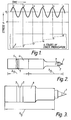
- Figures 2 and 3 show examples of ultrasonic systems suitable for generating high stresses in hard brittle materials.
- the system comprises a sharp tip 1 of hard material, for example tungsten carbide or even diamond, in a stainless steel holder 2.
- This assembly is screwed, by means of threaded shank 3, into a tuned horn connected to a transducer 4 operatively connected with piezoelectric ceramic rings 5.
- the total length of the apparatus is one wavelength, while in the embodiment of Figure 3, which shows a transducer with stepped output end, the total length is one half of a wavelength.
- the tip may become blunted after repeated use. It is possible to resharpen it but it is difficult since the tip is of hard material.
- the tip is a composite having a 1mm diameter core of a hard grade of material within a 3mm diameter outer sleeve of comparatively soft material. (By "comparatively soft” is meant softer than the core but harder than the material of the workpiece.) With this construction, the sleeve will wear down preferentially, leaving a reasonably sharp tip.
- FIG. 4 shows a schematic circuit for achieving this.
- the power supply 6 provides DC voltages to the output 7 and resonant drive 8 circuits.
- the switch mode output is driven by a VCO with PLL frequency control using a signal derived from the output current.
- the invention has been described with reference to the necessary high frequency vibrations being produced by piezoceramic transducer systems.
- the impulsive forces used to generate the cyclic stress can be produced by several means; viz. an ultrasonic transducer with tuned horn and cutting tip; an electromagnetic vibrator (frequency limit around 10 kHz); by mechanical means, using a cam; or hydraulically.
- the feature common to each excitation system is that it must operate at a high frequency, in the order of several kHz. It is believed that better control of the rate of crack propagation is achieved the higher the frequency. For example when cutting floor tiles which are typically 8-10mm thick, adequate control is provided by an ultrasonic system operating at 30 kHz. In concrete products where the stress is relieved by the presence of numerous internal voids in the structure, crack propagation would be much slower and consequently a lower frequency would be expected to provide adequate control e.g. around 10 kHz.
- the vibration generating and transmitting apparatus is essentially as described above. It is housed in a pistol type casing 9 with a trigger 10 for allowing connection between a RF input 11 and the piezoceramic transducer.
- the trigger 10 acts on a microswitch 12 which can operate a relay in the frequency converter unit.
- the trigger 10 is biased outwardly by spring 13 so that a positive action is required for the cyclic stress vibration to be set up.
- FIG 6 An external view of the tool of Figure 5 is shown in Figure 6, together with a ceramic tile cut by the tool.
- the cut made need not necessarily be linear, as is generally the case with existing tile cutting methods, but may be curved and, in fact, may include abrupt changes of direction.
- the crack By generating the crack over several impulses of the tip, the crack may increase in depth stepwisely until the workpiece breaks.
Landscapes
- Engineering & Computer Science (AREA)
- Mechanical Engineering (AREA)
- Mining & Mineral Resources (AREA)
- Life Sciences & Earth Sciences (AREA)
- Forests & Forestry (AREA)
- Processing Of Stones Or Stones Resemblance Materials (AREA)
- Perforating, Stamping-Out Or Severing By Means Other Than Cutting (AREA)
- Turning (AREA)
Claims (9)
- Verfahren zum Schneiden eines spröden Werkstücks entlang einer gewünschten Linie, wobei das Verfahren das Aufsetzen eines spitzen Werkzeugs auf die Oberfläche des Werkstücks, das Einwirken von Schwingungen auf das Werkzeug in einer Längsrichtung desselben und das Bewegen des Werkzeugs entlang der gewünschten Linie unter Ausübung von im wesentlichen gleichmäßigen, in Längsrichtung wirkenden Druck auf das Werkzeug umfaßt, dadurch gekennzeichnet, daß die Schwingungen mit einer Frequenz einwirken, die größer ist als 8 kHz, um einen Spalt in dem Werkstück zu erzeugen und auszudehnen, so daß Schneiden ausgeführt wird, ohne daß eine Biegekraft auf das Werkstück ausgeübt wird.
- Verfahren nach Anspruch 1, dadurch gekennzeichnet, daß das spröde Werkstück eine Keramikfliese ist und die Frequenz im Bereich von 30 kHz liegt.
- Verfahren nach Anspruch 1, dadurch gekennzeichnet, das das spröde Werkstück ein Betonerzeugnis ist und die Frequenz im Bereich von 10 kHz liegt.
- Verfahren nach einem der vorangehenden Ansprüche, das des weiteren den Einsatz von Ultraschallschwingungen eines piezokeramischen Wandlers zum Erzeugen der hochfrequenten Schwingungen umfaßt.
- Vorrichtung zum Ausführen des Verfahrens nach Anspruch 1, wobei die Vorrichtung einen piezokeramischen Wandler (5) zum Erzeugen von Schwingungen, eine Spitze (1), die auf das Werkstück aufgesetzt wird und eine größere Härte aufweist als das Werkstück, sowie eine Einrichtung zum Übertragen der Schwingungsenergie auf die Spitze umfaßt, dadurch gekennzeichnet, daß der Wandler Schwingungsenergie mit einer Frequenz von mehr als 8 kHz erzeugt und die Schwingungsenergie zugeführt wird, um das Werkzeug in einer Längsrichtung desselben in Schwingung zu versetzen.
- Vorrichtung nach Anspruch 5, wobei die Einrichtung zum Übertragen der Schwingungsenergie auf die Spitze ein abgestimmter Trichter ist.
- Vorrichtung nach Anspruch 5 oder Anspruch 6, wobei die Spitze (1) aus Wolframkarbid oder anderem Material äquivalenter Härte besteht.
- Vorrichtung nach Anspruch 7, wobei die Spitze (1) einen Kern aus vergleichsweise hartem Material und eine Ringhülse aus Material umfaßt, das vergleichsweise weich, jedoch härter als das Material des Werkstücks ist.
- Vorrichtung nach Anspruch 8, wobei der Kern einen Durchmesser von im wesentlichen 1 mm hat, und die Hülse einen Außendurchmesser von im wesentlichen 3 mm hat.
Applications Claiming Priority (2)
| Application Number | Priority Date | Filing Date | Title |
|---|---|---|---|
| GB8810976 | 1988-05-10 | ||
| GB888810976A GB8810976D0 (en) | 1988-05-10 | 1988-05-10 | Cutting brittle materials |
Publications (3)
| Publication Number | Publication Date |
|---|---|
| EP0341942A2 EP0341942A2 (de) | 1989-11-15 |
| EP0341942A3 EP0341942A3 (de) | 1991-03-27 |
| EP0341942B1 true EP0341942B1 (de) | 1996-04-24 |
Family
ID=10636613
Family Applications (1)
| Application Number | Title | Priority Date | Filing Date |
|---|---|---|---|
| EP89304600A Expired - Lifetime EP0341942B1 (de) | 1988-05-10 | 1989-05-08 | Schneiden von spröden Materialien |
Country Status (9)
| Country | Link |
|---|---|
| US (1) | US5195410A (de) |
| EP (1) | EP0341942B1 (de) |
| AT (1) | ATE137155T1 (de) |
| AU (1) | AU630107B2 (de) |
| CA (1) | CA1335902C (de) |
| DE (1) | DE68926315T2 (de) |
| ES (1) | ES2088894T3 (de) |
| GB (2) | GB8810976D0 (de) |
| ZA (1) | ZA893417B (de) |
Families Citing this family (28)
| Publication number | Priority date | Publication date | Assignee | Title |
|---|---|---|---|---|
| GB2246739B (en) * | 1990-06-08 | 1994-01-05 | S R A Dev Ltd | Method and apparatus for cutting an aperture in brittle material |
| JPH08506060A (ja) * | 1993-02-04 | 1996-07-02 | フアウペル テクステイルマシーネン コマンデイトゲゼルシヤフト | ウエブを超音波で切断し及び/又は超音波で溶接するための装置 |
| CH687241A5 (de) * | 1993-05-07 | 1996-10-31 | Walter Suter | Vorrichtung zum Schneiden von Endlos-Papier sowie ein Verfahren zu ihrem Betrieb. |
| GB9312699D0 (en) * | 1993-06-19 | 1993-08-04 | Young Michael J R | Apparatus for making an aperture in a tile |
| ATE187917T1 (de) * | 1994-09-28 | 2000-01-15 | Unilever Nv | Ultraschallschneidverfahren |
| DE4444853B4 (de) * | 1994-12-16 | 2006-09-28 | Hilti Ag | Handgerät zur materialabtragenden Bearbeitung mit elektroakustischem Wandler für die Erzeugung von Ultraschallschwingungen |
| US6032561A (en) * | 1997-09-18 | 2000-03-07 | Colborne Corporation | Apparatus for ultrasonic cutting of food products |
| US6070509A (en) * | 1997-09-18 | 2000-06-06 | Colbourne Corporation | Method for ultrasonic cutting of food products |
| US6470782B1 (en) * | 1997-09-25 | 2002-10-29 | Beldex Corporation | Scribe device |
| JP4203177B2 (ja) * | 1999-03-18 | 2008-12-24 | 株式会社ベルデックス | スクライブ方法および装置 |
| CA2287140C (en) * | 1999-10-13 | 2001-02-13 | Sudip Bhattacharjee | Process to fracture connecting rods and the like with resonance-fatigue |
| SE0201945D0 (sv) * | 2002-06-25 | 2002-06-25 | Nyfors Teknologi Ab | An apparatus and a method for cleaving thin rods |
| US20050028657A1 (en) * | 2003-08-04 | 2005-02-10 | Mitro Richard John | Tunable cutting device |
| CN100394897C (zh) * | 2004-08-03 | 2008-06-18 | 张毓笠 | 复合振动的超声骨骼手术仪 |
| US7823490B2 (en) * | 2006-10-04 | 2010-11-02 | The Boeing Company | Cutting sequence for net trimming a composite layup at an oblique angle |
| GB0625301D0 (en) | 2006-12-19 | 2007-01-24 | Airbus Uk Ltd | Method and system for making holes in composite materials |
| ITMO20080173A1 (it) * | 2008-06-12 | 2009-12-13 | Tecno Europa Srl | Apparati e metodi per frazionare manufatti ceramici |
| ITTO20080497A1 (it) * | 2008-06-25 | 2009-12-26 | Bottero Spa | Metodo e macchina per il troncaggio di una lastra di vetro |
| DE102009027688A1 (de) * | 2009-01-05 | 2010-07-08 | Robert Bosch Gmbh | Handgehaltene Elektrowerkzeugmaschine |
| DE102009045944A1 (de) * | 2009-10-23 | 2011-04-28 | Robert Bosch Gmbh | Schutzsensorik für handgehaltene Elektrowerkzeugmaschine |
| DE102009055408A1 (de) * | 2009-12-30 | 2011-07-07 | Robert Bosch GmbH, 70469 | Handgehaltenes Sprühgerät |
| DE102011078083A1 (de) * | 2011-06-27 | 2012-12-27 | Robert Bosch Gmbh | Handgeführtes Elektrowerkzeug mit einem schwingfähigen Anregungsaktor |
| US20140326116A1 (en) * | 2013-05-03 | 2014-11-06 | Tyco Electronics Corporation | Die component for a press device |
| TWI523718B (zh) * | 2014-08-21 | 2016-03-01 | 周振嘉 | 應用於超音波加工的工具單元 |
| DE102016214699A1 (de) * | 2016-08-08 | 2018-02-08 | Sauer Gmbh | Verfahren und Vorrichtung zur Bearbeitung eines Werkstücks an einer numerisch gesteuerten Werkzeugmaschine |
| CZ307545B6 (cs) * | 2017-11-01 | 2018-11-21 | VĂšTS, a.s. | Způsob a zařízení k dělení tyčovitého nebo trubkovitého předmětu vytvořeného z křehkého materiálu |
| WO2019184975A1 (zh) * | 2018-03-28 | 2019-10-03 | 南京德朔实业有限公司 | 电动工具及其控制方法 |
| CN109176916A (zh) * | 2018-09-30 | 2019-01-11 | 广东工业大学 | 一种瓷砖的新型加工系统 |
Family Cites Families (16)
| Publication number | Priority date | Publication date | Assignee | Title |
|---|---|---|---|---|
| US2806328A (en) * | 1952-01-31 | 1957-09-17 | Council Scient Ind Res | Vibratory tools |
| US3023547A (en) * | 1959-12-07 | 1962-03-06 | Western Electric Co | Ultrasonic cutting tool |
| GB1115537A (en) * | 1966-05-30 | 1968-05-29 | Otto Thaning | Improvements in the sub-dividing of crystalline materials |
| GB1362484A (en) * | 1972-10-03 | 1974-08-07 | Standard Telephones Cables Ltd | Engraving apparatus and method |
| US3909911A (en) * | 1973-04-30 | 1975-10-07 | Orthodyne Electronics | Method for removing insulating and shielding materials from flat conductors, circuits and components |
| SU536850A1 (ru) * | 1974-05-30 | 1976-11-30 | Государственный Научно-Исследовательский Институт Машиноведения | Способ автоматической настройки ультразвуковых станков |
| US3999453A (en) * | 1974-12-12 | 1976-12-28 | Cavitron Corporation | Ultrasonic cutting apparatus |
| SU588664A1 (ru) * | 1976-07-09 | 1978-01-15 | Каунасский Политехнический Институт Им.Антанаса Снечкуса | Устройство дл питани пьезокерамического преобразовател |
| GB2016350B (en) * | 1978-02-20 | 1982-05-26 | Citizen Watch Co Ltd | Ultrasonic cutting tool |
| SU772875A1 (ru) * | 1978-07-14 | 1980-10-23 | Предприятие П/Я М-5174 | Способ обработки керамических изделий |
| JPS5935743B2 (ja) * | 1979-01-24 | 1984-08-30 | 株式会社井上ジャパックス研究所 | 超音波研削加工装置 |
| GB2082565B (en) * | 1980-08-20 | 1984-04-11 | Plessey Co Ltd | Vibrating cutter for optical fibres |
| US4567797A (en) * | 1984-01-30 | 1986-02-04 | Folk Donald C | Ultrasonic cutting apparatus and methods |
| SU1220740A1 (ru) * | 1984-03-23 | 1986-03-30 | Московский Ордена Ленина И Ордена Октябрьской Революции Авиационный Институт Им.Серго Орджоникидзе | Способ механической обработки |
| US4585152A (en) * | 1984-12-13 | 1986-04-29 | Branson Ultrasonics Corporation | Method and apparatus for degating parts using ultrasonic energy |
| DE3722546A1 (de) * | 1987-07-08 | 1989-01-26 | Singh Amar Jit | Verfahren zum schneiden, ritzen oder abloesen von stoffen, z. b. bauteilen |
-
1988
- 1988-05-10 GB GB888810976A patent/GB8810976D0/en active Pending
-
1989
- 1989-05-08 AT AT89304600T patent/ATE137155T1/de not_active IP Right Cessation
- 1989-05-08 ES ES89304600T patent/ES2088894T3/es not_active Expired - Lifetime
- 1989-05-08 US US07/349,455 patent/US5195410A/en not_active Expired - Lifetime
- 1989-05-08 GB GB8910512A patent/GB2218374B/en not_active Expired - Lifetime
- 1989-05-08 DE DE68926315T patent/DE68926315T2/de not_active Expired - Fee Related
- 1989-05-08 EP EP89304600A patent/EP0341942B1/de not_active Expired - Lifetime
- 1989-05-09 CA CA000599117A patent/CA1335902C/en not_active Expired - Fee Related
- 1989-05-09 ZA ZA893417A patent/ZA893417B/xx unknown
- 1989-08-30 AU AU40871/89A patent/AU630107B2/en not_active Ceased
Also Published As
| Publication number | Publication date |
|---|---|
| ES2088894T3 (es) | 1996-10-01 |
| GB8810976D0 (en) | 1988-06-15 |
| GB2218374B (en) | 1992-05-06 |
| ZA893417B (en) | 1990-01-31 |
| ATE137155T1 (de) | 1996-05-15 |
| AU4087189A (en) | 1991-03-07 |
| US5195410A (en) | 1993-03-23 |
| EP0341942A2 (de) | 1989-11-15 |
| EP0341942A3 (de) | 1991-03-27 |
| DE68926315D1 (de) | 1996-05-30 |
| GB2218374A (en) | 1989-11-15 |
| DE68926315T2 (de) | 1996-10-31 |
| GB8910512D0 (en) | 1989-06-21 |
| AU630107B2 (en) | 1992-10-22 |
| CA1335902C (en) | 1995-06-13 |
Similar Documents
| Publication | Publication Date | Title |
|---|---|---|
| EP0341942B1 (de) | Schneiden von spröden Materialien | |
| US20040251290A1 (en) | Cutting method for brittle non-metallic materials (two variants) | |
| JP2000143265A (ja) | 脆性材料とプラスチックからなる積層体を切断する方法及び装置 | |
| MX9800303A (es) | Transductor ultrasonico. | |
| US3679526A (en) | Sonic or ultrasonic cutting apparatus | |
| US4071385A (en) | Ultrasonic inlaid article | |
| JP7332150B2 (ja) | 合成樹脂の切断加工方法及び切断加工装置 | |
| JPH10291084A (ja) | 脆性材料のレーザ加工方法及び装置 | |
| JP2000119031A (ja) | スクライブ方法及び装置 | |
| US3157329A (en) | Apparatus for breaking glass | |
| KR100845391B1 (ko) | 깨어지기 쉬운 비금속 물질의 절단방법(두가지의 변형) | |
| EP2998523A1 (de) | Gasturbinenmotor | |
| EP2389273B1 (de) | Ultraschallbehandlungsvorrichtung | |
| SU996347A1 (ru) | Способ резки стекла А.А.Малышева | |
| WO2004011210A3 (en) | Apparatus and method for cutting sheet-type work material using a blade reciprocated via a tuned resonator | |
| JPH06143099A (ja) | 超音波加工機 | |
| RU2206527C2 (ru) | Способ резки хрупких неметаллических материалов | |
| JPH05221673A (ja) | 割断加工方法 | |
| Sitek et al. | Concrete and rock cutting using modulated waterjets | |
| Samal | Study of Parameters of Ultrasonic machining | |
| JP2001018193A (ja) | 超音波カッタ−装置 | |
| RU2011481C1 (ru) | Устройство для сверления | |
| JPH05228894A (ja) | 冷凍食品切断器具 | |
| SU1004119A1 (ru) | Способ изготовлени изделий с колотой фактурой из камн | |
| Tyrrell | Ultrasonic Machining |
Legal Events
| Date | Code | Title | Description |
|---|---|---|---|
| PUAI | Public reference made under article 153(3) epc to a published international application that has entered the european phase |
Free format text: ORIGINAL CODE: 0009012 |
|
| AK | Designated contracting states |
Kind code of ref document: A2 Designated state(s): AT BE CH DE ES FR GR IT LI LU NL SE |
|
| PUAL | Search report despatched |
Free format text: ORIGINAL CODE: 0009013 |
|
| AK | Designated contracting states |
Kind code of ref document: A3 Designated state(s): AT BE CH DE ES FR GR IT LI LU NL SE |
|
| 17P | Request for examination filed |
Effective date: 19910917 |
|
| 17Q | First examination report despatched |
Effective date: 19921203 |
|
| GRAH | Despatch of communication of intention to grant a patent |
Free format text: ORIGINAL CODE: EPIDOS IGRA |
|
| GRAA | (expected) grant |
Free format text: ORIGINAL CODE: 0009210 |
|
| AK | Designated contracting states |
Kind code of ref document: B1 Designated state(s): AT BE CH DE ES FR GR IT LI LU NL SE |
|
| PG25 | Lapsed in a contracting state [announced via postgrant information from national office to epo] |
Ref country code: GR Free format text: LAPSE BECAUSE OF FAILURE TO SUBMIT A TRANSLATION OF THE DESCRIPTION OR TO PAY THE FEE WITHIN THE PRESCRIBED TIME-LIMIT Effective date: 19960424 Ref country code: AT Effective date: 19960424 |
|
| REF | Corresponds to: |
Ref document number: 137155 Country of ref document: AT Date of ref document: 19960515 Kind code of ref document: T |
|
| REF | Corresponds to: |
Ref document number: 68926315 Country of ref document: DE Date of ref document: 19960530 |
|
| PG25 | Lapsed in a contracting state [announced via postgrant information from national office to epo] |
Ref country code: LU Free format text: LAPSE BECAUSE OF NON-PAYMENT OF DUE FEES Effective date: 19960531 |
|
| ITF | It: translation for a ep patent filed | ||
| REG | Reference to a national code |
Ref country code: CH Ref legal event code: NV Representative=s name: KIRKER & CIE SA |
|
| PG25 | Lapsed in a contracting state [announced via postgrant information from national office to epo] |
Ref country code: SE Effective date: 19960724 |
|
| ET | Fr: translation filed | ||
| REG | Reference to a national code |
Ref country code: ES Ref legal event code: FG2A Ref document number: 2088894 Country of ref document: ES Kind code of ref document: T3 |
|
| REG | Reference to a national code |
Ref country code: ES Ref legal event code: FG2A Ref document number: 2088894 Country of ref document: ES Kind code of ref document: T3 |
|
| PLBE | No opposition filed within time limit |
Free format text: ORIGINAL CODE: 0009261 |
|
| STAA | Information on the status of an ep patent application or granted ep patent |
Free format text: STATUS: NO OPPOSITION FILED WITHIN TIME LIMIT |
|
| 26N | No opposition filed | ||
| PGFP | Annual fee paid to national office [announced via postgrant information from national office to epo] |
Ref country code: FR Payment date: 20020508 Year of fee payment: 14 |
|
| PGFP | Annual fee paid to national office [announced via postgrant information from national office to epo] |
Ref country code: DE Payment date: 20020516 Year of fee payment: 14 |
|
| PGFP | Annual fee paid to national office [announced via postgrant information from national office to epo] |
Ref country code: CH Payment date: 20020517 Year of fee payment: 14 |
|
| PGFP | Annual fee paid to national office [announced via postgrant information from national office to epo] |
Ref country code: NL Payment date: 20020529 Year of fee payment: 14 |
|
| PGFP | Annual fee paid to national office [announced via postgrant information from national office to epo] |
Ref country code: ES Payment date: 20020530 Year of fee payment: 14 |
|
| PGFP | Annual fee paid to national office [announced via postgrant information from national office to epo] |
Ref country code: BE Payment date: 20020717 Year of fee payment: 14 |
|
| PG25 | Lapsed in a contracting state [announced via postgrant information from national office to epo] |
Ref country code: ES Free format text: LAPSE BECAUSE OF NON-PAYMENT OF DUE FEES Effective date: 20030509 |
|
| PG25 | Lapsed in a contracting state [announced via postgrant information from national office to epo] |
Ref country code: LI Free format text: LAPSE BECAUSE OF NON-PAYMENT OF DUE FEES Effective date: 20030531 Ref country code: CH Free format text: LAPSE BECAUSE OF NON-PAYMENT OF DUE FEES Effective date: 20030531 Ref country code: BE Free format text: LAPSE BECAUSE OF NON-PAYMENT OF DUE FEES Effective date: 20030531 |
|
| BERE | Be: lapsed |
Owner name: *S.R.A. DEVELOPMENTS LTD Effective date: 20030531 |
|
| PG25 | Lapsed in a contracting state [announced via postgrant information from national office to epo] |
Ref country code: NL Free format text: LAPSE BECAUSE OF NON-PAYMENT OF DUE FEES Effective date: 20031201 |
|
| PG25 | Lapsed in a contracting state [announced via postgrant information from national office to epo] |
Ref country code: DE Free format text: LAPSE BECAUSE OF NON-PAYMENT OF DUE FEES Effective date: 20031202 |
|
| REG | Reference to a national code |
Ref country code: CH Ref legal event code: PL |
|
| PG25 | Lapsed in a contracting state [announced via postgrant information from national office to epo] |
Ref country code: FR Free format text: LAPSE BECAUSE OF NON-PAYMENT OF DUE FEES Effective date: 20040130 |
|
| NLV4 | Nl: lapsed or anulled due to non-payment of the annual fee |
Effective date: 20031201 |
|
| REG | Reference to a national code |
Ref country code: FR Ref legal event code: ST |
|
| REG | Reference to a national code |
Ref country code: ES Ref legal event code: FD2A Effective date: 20030509 |
|
| PG25 | Lapsed in a contracting state [announced via postgrant information from national office to epo] |
Ref country code: IT Free format text: LAPSE BECAUSE OF NON-PAYMENT OF DUE FEES;WARNING: LAPSES OF ITALIAN PATENTS WITH EFFECTIVE DATE BEFORE 2007 MAY HAVE OCCURRED AT ANY TIME BEFORE 2007. THE CORRECT EFFECTIVE DATE MAY BE DIFFERENT FROM THE ONE RECORDED. Effective date: 20050508 |