EP0341911B1 - Optischer Koppler aus Fluoridglasfasern und Herstellungsmethode - Google Patents
Optischer Koppler aus Fluoridglasfasern und Herstellungsmethode Download PDFInfo
- Publication number
- EP0341911B1 EP0341911B1 EP89304532A EP89304532A EP0341911B1 EP 0341911 B1 EP0341911 B1 EP 0341911B1 EP 89304532 A EP89304532 A EP 89304532A EP 89304532 A EP89304532 A EP 89304532A EP 0341911 B1 EP0341911 B1 EP 0341911B1
- Authority
- EP
- European Patent Office
- Prior art keywords
- optic fibres
- fibres
- temperature
- heating
- optic
- Prior art date
- Legal status (The legal status is an assumption and is not a legal conclusion. Google has not performed a legal analysis and makes no representation as to the accuracy of the status listed.)
- Expired - Lifetime
Links
Images

Classifications
-
- G—PHYSICS
- G02—OPTICS
- G02B—OPTICAL ELEMENTS, SYSTEMS OR APPARATUS
- G02B6/00—Light guides; Structural details of arrangements comprising light guides and other optical elements, e.g. couplings
- G02B6/24—Coupling light guides
- G02B6/245—Removing protective coverings of light guides before coupling
-
- G—PHYSICS
- G02—OPTICS
- G02B—OPTICAL ELEMENTS, SYSTEMS OR APPARATUS
- G02B6/00—Light guides; Structural details of arrangements comprising light guides and other optical elements, e.g. couplings
- G02B6/24—Coupling light guides
- G02B6/26—Optical coupling means
- G02B6/28—Optical coupling means having data bus means, i.e. plural waveguides interconnected and providing an inherently bidirectional system by mixing and splitting signals
- G02B6/2804—Optical coupling means having data bus means, i.e. plural waveguides interconnected and providing an inherently bidirectional system by mixing and splitting signals forming multipart couplers without wavelength selective elements, e.g. "T" couplers, star couplers
- G02B6/2821—Optical coupling means having data bus means, i.e. plural waveguides interconnected and providing an inherently bidirectional system by mixing and splitting signals forming multipart couplers without wavelength selective elements, e.g. "T" couplers, star couplers using lateral coupling between contiguous fibres to split or combine optical signals
- G02B6/2835—Optical coupling means having data bus means, i.e. plural waveguides interconnected and providing an inherently bidirectional system by mixing and splitting signals forming multipart couplers without wavelength selective elements, e.g. "T" couplers, star couplers using lateral coupling between contiguous fibres to split or combine optical signals formed or shaped by thermal treatment, e.g. couplers
-
- Y—GENERAL TAGGING OF NEW TECHNOLOGICAL DEVELOPMENTS; GENERAL TAGGING OF CROSS-SECTIONAL TECHNOLOGIES SPANNING OVER SEVERAL SECTIONS OF THE IPC; TECHNICAL SUBJECTS COVERED BY FORMER USPC CROSS-REFERENCE ART COLLECTIONS [XRACs] AND DIGESTS
- Y10—TECHNICAL SUBJECTS COVERED BY FORMER USPC
- Y10S—TECHNICAL SUBJECTS COVERED BY FORMER USPC CROSS-REFERENCE ART COLLECTIONS [XRACs] AND DIGESTS
- Y10S65/00—Glass manufacturing
- Y10S65/15—Nonoxygen containing chalogenides
- Y10S65/16—Optical filament or fiber treatment with fluorine or incorporating fluorine in final product
Definitions
- the present invention relates to optical couplers formed from optic fibres composed of fluoride glass.
- Fluoride type glasses normally containing fluorozirconate (ZrF4) and optic fibres formed from such glasses are disclosed in Br Telecom Technol J Vol 5 No 2 April 1987 "Progress in Fluoride Fibres for Optical Communications” - P W France et al and in a paper entitled “Properties of Fluorozirconate Fibres for Applications in the 0.5 to 4.5 Micrometre Region" by P W France et al which was presented at the SPIE Conference at San Diego in August 1987.
- fluoride fibres are the subject of European Patent Application No 170380.
- fluoride glass includes but is not limited to all the fluoride-containing glasses described in the above papers and all the fluoride-containing glasses within the scope of the disclosure of the above patent application.
- optic fibres composed of fluoride glass are their increased bandwidth which results in transmission in the far infra-red portion of the spectrum.
- optic fibres are likely to have future applications in telecommunications, their most important use presently is in optical fibre sensors.
- For long term stability of the measurements of such sensors there is a need to monitor input power to the sensor for use as a reference, and this is only possible using a directional coupler of some description.
- optical couplers for fluoride optic fibres in order to enable the power of one laser to be split between a number of sensors, particularly in view of the high cost of the lasers used in such applications.
- the fibres are disposed in a slot in a carbon core within a radio frequency heating arrangement and heated to a temperature of the order of 1600°C to 1800°C. At such temperatures the carbon core would oxidise in a normal atmosphere.
- the fibres are disposed within a tungsten heating coil which during the heating process is at a temperature high enough for it to emit bright white light. Under these conditions the tungsten heating coil would not be operated in a normal atmosphere.
- the present invention provides a method of forming an optical coupler from two or more optic fibres comprising disposing the optic fibres across one another so as to bring their claddings into contact, and tensioning and heating the optic fibres in an oxygen-free atmosphere so as to fuse together at least the contacting portions of their claddings, characterised in that the optic fibres are composed of a fluoride glass, and the heating is performed to a temperature corresponding to a glass viscosity in the range 100 Pa.s to 100 kPa.s.
- optical couplers of fluoride glass may be produced with a reproducible coupling ratio, despite the rapid variation in viscosity with temperature, typically corresponding to a temperature range from 300°C to 340°C over the above viscosity range.
- the temperature employed corresponds to a glass viscosity in the range 1 kPa.s to 10 kPa.s.
- the temperature is sensed such as to provide a feedback signal and the heating is controlled by said feedback signal.
- the sensed temperature is maintained constant at least during the tensioning of the fibres to within plus or minus 3°C, more preferably within plus or minus 1°C.
- the optic fibres are disposed closely adjacent a surface of a heated body so as to be maintained in thermal equilibrium therewith, the feedback signal being derived from sensing the temperature of the heated body.
- the optic fibres may be composed of ZBLAN glass and may be heated to a temperature of 323°C plus or minus 10°c and are subsequently optionally cooled by between 1°C and 2°C prior to terminating heating.
- a ZBLAN glass of composition ZrF4 - BaF2 - LaF3 - AlF3 - NaF - PbF2 the preferred temperature range is 323°C plus or minus 3°C, more preferably plus or minus 1°C.
- the tension applied to the optic fibres is controlled in dependence upon the extension of the fibres so as to maintain a stress in the optic fibres which is in the range 104 Pa to 106 Pa, more preferably in the range 0.5 times 105 Pa to 1.5 times 105 Pa.
- the invention also includes within its scope optical couplers obtained by a method in accordance with the invention.
- oxygen As well as excluding oxygen from the atmosphere surrounding the heated optic fibres, it is also desirable to exclude moisture.
- a variety of unreactive gases or vapours may be used to exclude oxygen, such as nitrogen, the inert gases, carbon dioxide, and heat-stable unreactive organic compounds such as halo-carbons, particularly fluorinated hydrocarbons.
- oxygen such as nitrogen, the inert gases, carbon dioxide, and heat-stable unreactive organic compounds
- halo-carbons particularly fluorinated hydrocarbons.
- hydrogen it is undesirable to use hydrogen since this adversely affects the properties of fluoride glass.
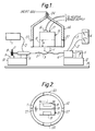
- the apparatus shown comprises an electric heater 15 which is located (by means not shown) within a shroud 14 through which inert gas such as nitrogen or argon for example at 0.1 bar is conducted through inlet 24 to provide the required oxygen-free atmosphere.
- the heater 15 incorporates a slot 18 which is also shown in Figure 2 and the shroud 14 incorporates a slot 27, the height H of the slot 18 being sufficient to enable the heater and shroud assembly to be lowered over a twisted pair of optic fibres 2, 3 in the direction indicated by the arrow Y. In this condition the optic fibres are virtually enclosed by an oxygen-free atmosphere and are located within slot 18 but do not contact the sides thereof.
- the thickness T of the slot (as shown in Figure 2) is suitably 0.75mm.
- the optic fibres 2, 3 are tensioned between a holder 5 and a holder 6, the former being rotatable about its axis by a stepper motor 9 which drives it via a wormwheel 8 and a gear 7.
- a stepper motor 9 which drives it via a wormwheel 8 and a gear 7.
- the stepper motor 9 and holder 5 are mounted on a common mounting 10 which is in turn movable on a base 13 in the direction of the tensioned optic fibres by a further stepper motor (not shown).
- the holder 6 is mounted on an air bearing (not shown) on a mounting 12 which is in turn mounted by a mechanical bearing (not shown) on base 13 and is movable towards and away from mounting 10 via a further stepper motor (not shown).
- the tension in the optic fibres 2, 3 is measured by a meter 11 which is mounted on mounting 12 and the stress, namely the tension divided by the cross sectional area of the optic fibres, is calculated by a computer (not shown) in dependence upon the original cross section of the optic fibres and the extension of the optic fibres (measured by means not shown) during the operation of the apparatus.
- the arrangement shown in Figure 1 is set up by splicing the optic fibre onto a laser 1 of the same wavelength as that at which the finished coupler is to operate.
- a length of free fibre is then prepared for coupling by removing the primary coating and cleaning thoroughly using propanol.
- the output from that fibre 3 is then calibrated as being 100% power.
- This length of fibre 3 is broken off and mounted between holders 5 and 6 ready for coupling.
- a second length 2 of fibre is then prepared identically but once mounted between holders 5 and 6 remains energised by laser 1 and the output ends of both fibres are inserted into the dual measuring heads of power monitoring equipment 4.
- two turns are applied to the optic fibre 2 and 3 by the rotatable holder 5.
- the heater block 15 is then heated by an electric cartridge heater 16 until its temperature as monitored by a thermocouple 17 which extends to a position closely adjacent the walls of slot 18 reaches a temperature of 320°C.
- This temperature is maintained by a "eurotherm" power controller in dependence upon a feedback signal from the thermocouple 17 in order to control the temperature to the required degree of accuracy.
- the stepper motors (not shown) are then turned on to pull apart the holders 5 and 6 and maintain a stress of 105 Pa in the fibres, corresponding to a tension of 1.25 grammes (0.0123N) for 140 micrometre OD optic fibres. Pulling of the fibres is then maintained until the appropriate coupling ratio, as recorded by the measuring equipment 4, is reached.
- the length L of the heater block 15 is suitably approximately 10 millimetres.
- Recesses 19 are provided in the heater block and recesses at 20 are provided in the shroud 14 in order to enable the heater 15 and shroud to be accurately located.
- the heater 15 and shroud 14 are lifted from the partially fused optic fibres 2 and 3 (which are suitably multimode fibres) and the coupled region is then packaged in a channel 26 ( Figure 5) of a block 28 of either flint glass or float glass with a similar coefficient of thermal expansion to that of the fluoride fibres, thus giving mechanical strength and thermal stability to the optical coupler 29 formed thereby.
- the coupled fibres 2 and 3 are embedded in channel 26 with epoxy resin.
- FIGS 3 and 4 show an alternative heater in which the nitrogen or other oxygen-free gas is directed through the heater block 15′ via an inlet 24′ and exits from an outlet 23 which is formed at the base of a central waisted portion of a slot 18′ which is otherwise similar to the slot 18 shown in Figures 1 and 2. Accordingly the shroud 14 shown in Figures 1 and 2 may be dispensed with in this embodiment.
- the heater block 15′ is sandwiched between end cheeks 21 of PTFE and communicates with recesses 22 formed in these end cheeks which are adapted to be located on locating supports (not shown).
- Two cartridge heaters 25 extend downwardly into the heater block 15′ as shown in Figure 4 and lie on opposite sides of slot 18′.
- thermocouple 30 extends downwardly through the heater block 15′ to a position closely adjacent the walls of the slot 18′.
- This heater arrangement may be controlled by a suitable power supply in dependence upon a feedback signal from the thermocouple 30.
- the width of the slot 18′ (corresponding to the dimension T shown in Figure 2) is suitably 0.75mm. at the central waisted portion and the length (corresponding to the dimension L shown in Figure 2) is suitably approximately 10 millimetres.
- the heater block 15′ is suitably made of copper.
Landscapes
- Physics & Mathematics (AREA)
- General Physics & Mathematics (AREA)
- Optics & Photonics (AREA)
- Glass Compositions (AREA)
- Lasers (AREA)
Claims (14)
- Verfahren zum Bilden eines optischen Kopplers (29) aus zwei oder mehr Optikfasern (2, 3), das umfaßt:
ein Anordnen der Optikfasern längs zueinander, um ihre Umhüllungen in Kontakt zu bringen, und Spannen und Erhitzen der Optikfasern in einer sauerstoffreien Atmosphäre, um zumindest die Teile ihrer Umhüllungen zu verschmelzen, die in Kontakt sind,
dadurch gekennzeichnet, daß
die Optikfasern (2, 3) aus einem Fluoridglas zusammengesetzt sind, und daß das Heizen auf eine Temperatur durchgeführt wird, die einer Glasviskosität in dem Bereich von 100 Pa.s bis 100 kPa.s entspricht. - Verfahren nach Anspruch 1, wobei die Temperatur derart erfaßt wird, um ein Rückkoppelsignal zu schaffen, und wobei das Heizen durch das Rückkoppelsignal gesteuert wird.
- Verfahren nach Anspruch 2, wobei die Temperatur zumindest während des Spannens der Fasern innerhalb von ± 3°C konstant gehalten wird.
- Verfahren nach Anspruch 2 oder 3, wobei die Optikfasern (2, 3) nahe benachbart einer Oberfläche eines erhitzten Körpers (15) angeordnet sind, um im thermischen Gleichgewicht damit gehalten zu werden, wobei das Rückkoppelsignal vom Erfassen der Temperatur des erhitzten Körpers abgeleitet wird.
- Verfahren nach Anspruch 4, wobei die Optikfasern (2, 3) innerhalb eines Kanals (18) in dem erhitzten Körper angeordnet sind.
- Verfahren nach einem der vorangehenden Ansprüche, wobei die Spannung in Abhängigkeit von der Ausdehnung der Optikfasern (2, 3) gesteuert wird.
- Verfahren nach einem der vorangehenden Ansprüche, wobei eine Strahlung durch die Optikfasern (2, 3) während des Heizens und Spannens von ihnen gerichtet wird, das Koppeln der Strahlung zwischen Optikfasern überwacht wird und das Heizen und/oder Spannen in Antwort auf das Erreichen eines vorbestimmten Kopplungsverhältnisses beendet wird.
- Verfahren nach einem der vorangehenden Ansprüche, wobei die Optikfasern (2, 3) aus ZBLAN -Glas zusammengesetzt sind und auf eine Temperatur von 323°C ± 10°C erhitzt werden und darauffolgend optional um zwischen 1°C und 2°C gekühlt werden, bevor das Heizen beendet wird.
- Verfahren nach einem der Ansprüche 1 bis 7, wobei die Optikfasern (2, 3) aus ZBLAN -Glas zusammengesetzt sind, das die Zusammensetzung ZrF₄ - BaF₂ - LaF₃ - AlF₃ - NaF - PbF₂ aufweist, und die auf eine Temperatur von 323°C ± 3°C erhitzt werden.
- Verfahren nach Anspruch 9, wobei die Optikfasern (2, 3) auf eine Temperatur von 323°C ± 1°C erhitzt werden.
- Verfahren nach einem der vorangehenden Ansprüche, wobei die Spannung auf einem Pegel gehalten wird, der ausreichend ist, um eine Beanspruchung in den Optikfasern (2, 3) in dem Bereich von 10⁴ Pa bis 10⁶ Pa zu induzieren.
- Verfahren nach Anspruch 11, wobei die Beanspruchung in dem Bereich von 0,5 x 10⁵ Pa bis 1,5 x 10⁵ Pa liegt.
- Verfahren nach einem der vorangehenden Ansprüche, das den weiteren Schritt eines Packens der gekoppelten optischen Fasern (2, 3) in einem schützenden Medium (28) umfaßt.
- Optischer Koppler (29), der durch ein Verfahren hergestellt ist, wie es in einem der vorangehenden Ansprüche beansprucht ist.
Priority Applications (1)
| Application Number | Priority Date | Filing Date | Title |
|---|---|---|---|
| AT89304532T ATE84286T1 (de) | 1988-05-09 | 1989-05-05 | Optischer koppler aus fluoridglasfasern und herstellungsmethode. |
Applications Claiming Priority (2)
| Application Number | Priority Date | Filing Date | Title |
|---|---|---|---|
| GB888810907A GB8810907D0 (en) | 1988-05-09 | 1988-05-09 | Fluoride glass optical coupler & method of manufacture |
| GB8810907 | 1988-05-09 |
Publications (2)
| Publication Number | Publication Date |
|---|---|
| EP0341911A1 EP0341911A1 (de) | 1989-11-15 |
| EP0341911B1 true EP0341911B1 (de) | 1993-01-07 |
Family
ID=10636574
Family Applications (1)
| Application Number | Title | Priority Date | Filing Date |
|---|---|---|---|
| EP89304532A Expired - Lifetime EP0341911B1 (de) | 1988-05-09 | 1989-05-05 | Optischer Koppler aus Fluoridglasfasern und Herstellungsmethode |
Country Status (10)
| Country | Link |
|---|---|
| US (1) | US5139550A (de) |
| EP (1) | EP0341911B1 (de) |
| JP (1) | JP2581818B2 (de) |
| AT (1) | ATE84286T1 (de) |
| AU (1) | AU612840B2 (de) |
| CA (1) | CA1336132C (de) |
| DE (1) | DE68904238T2 (de) |
| ES (1) | ES2037953T3 (de) |
| GB (1) | GB8810907D0 (de) |
| WO (1) | WO1989010901A1 (de) |
Families Citing this family (8)
| Publication number | Priority date | Publication date | Assignee | Title |
|---|---|---|---|---|
| US5205851A (en) * | 1990-10-12 | 1993-04-27 | Sumitomo Electric Industries, Ltd. | Method and apparatus for producing optical fiber coupler |
| KR20030092750A (ko) * | 2002-05-31 | 2003-12-06 | 한국전자통신연구원 | 다중 광섬유 커플러 제작장치 |
| DE102004028310B9 (de) * | 2004-06-12 | 2010-10-07 | Schott Ag | Verfahren und Vorrichtung zum Herstellen des Abschlusses eines Lichtleitfaserbündels |
| BRPI0519306A2 (pt) | 2004-12-30 | 2009-01-06 | Medivir Ab | compostos éteis no tratamento de hiv |
| GB0513835D0 (en) | 2005-07-07 | 2005-08-10 | Medivir Ab | HIV inhibitors |
| CN103809244B (zh) * | 2014-02-13 | 2017-08-29 | 一诺仪器(中国)有限公司 | 一种光纤热剥装置的加热控制系统及方法 |
| US11033333B2 (en) | 2017-04-06 | 2021-06-15 | Stryker European Holdings I, Llc | Plate selection user interface and design tool with database |
| IL317146A (en) * | 2019-08-21 | 2025-01-01 | Univ Laval | Method of coupling optical fibers, and optical coupler |
Family Cites Families (28)
| Publication number | Priority date | Publication date | Assignee | Title |
|---|---|---|---|---|
| GB1252126A (de) * | 1967-11-08 | 1971-11-03 | ||
| DE2812346A1 (de) * | 1977-03-23 | 1978-09-28 | Tokyo Shibaura Electric Co | Lichtverteiler |
| US4291940A (en) * | 1977-06-13 | 1981-09-29 | Canadian Patents & Development Ltd. | Low loss access coupler for multimode optical fiber distribution systems |
| CA1123642A (en) * | 1979-07-04 | 1982-05-18 | Alexander W. Lightstone | Multimode optical fiber coupler |
| CA1118621A (en) * | 1979-11-01 | 1982-02-23 | Lawrence C. Smyth | Method and jig for making optical fiber couplers |
| JPS5714801A (en) * | 1980-06-30 | 1982-01-26 | Fujikura Ltd | Production of optical fiber coupler |
| DE3035089A1 (de) * | 1980-09-17 | 1982-04-22 | Siemens AG, 1000 Berlin und 8000 München | Verfahren zur herstellung von verteiler- und mischerelementen fuer die optische nachrichtentechnik und verfahren zur herstellung einer fuer das erstgenannte verfahren notwendigen vorform |
| US4377403A (en) * | 1980-09-29 | 1983-03-22 | The United States Of America As Represented By The Secretary Of The Navy | Method of fabricating a fused single-mode fiber bidirectional coupler |
| US4336047A (en) * | 1981-01-02 | 1982-06-22 | The United States Of America As Represented By The Secretary Of The Navy | Method for fabricating single-mode and multimode fiber optic access couplers |
| US4426215A (en) * | 1981-10-07 | 1984-01-17 | International Telephone And Telegraph Corporation | Method of fabricating a low loss fused biconical taper fiber optic coupler |
| JPS5891403A (ja) * | 1981-11-26 | 1983-05-31 | Toshiba Corp | 光フアイバ加工装置 |
| US4490163A (en) * | 1982-03-22 | 1984-12-25 | U.S. Philips Corporation | Method of manufacturing a fiber-optical coupling element |
| JPS59142521A (ja) * | 1983-02-03 | 1984-08-15 | Sumitomo Electric Ind Ltd | 光分岐素子とその製造方法 |
| JPS59195615A (ja) * | 1983-04-21 | 1984-11-06 | Sumitomo Electric Ind Ltd | 光フアイバ分岐の製造方法 |
| US4630890A (en) * | 1983-06-22 | 1986-12-23 | At&T Bell Laboratories | Exposed core optical fibers, and method of making same |
| GB2150703B (en) * | 1983-11-30 | 1987-03-11 | Standard Telephones Cables Ltd | Single mode fibre directional coupler |
| FR2563826B1 (fr) * | 1984-05-07 | 1991-08-30 | Verre Fluore Sa | Procedes de fabrication de fibres et de composants optiques en verres fluores et appareils destines a les mettre en oeuvre |
| GB8419829D0 (en) * | 1984-08-03 | 1984-09-05 | British Telecomm | Treating glass compositions |
| US4652288A (en) * | 1984-08-04 | 1987-03-24 | Horiba, Ltd. | Method of producing infrared image guide |
| AU569803B2 (en) * | 1984-09-06 | 1988-02-18 | Hitachi Limited | Optical fibre star coupler |
| JPS6165204A (ja) * | 1984-09-06 | 1986-04-03 | Hitachi Ltd | 光スタ−カプラおよびその製造方法 |
| US4799949A (en) * | 1985-08-15 | 1989-01-24 | Corning Glass Works | Method of making low loss fiber optic coupler |
| US4704151A (en) * | 1985-08-15 | 1987-11-03 | Corning Glass Works | Method for drawing fiber optic coupler |
| US4773924A (en) * | 1985-08-15 | 1988-09-27 | Corning Glass Works | Fiber optic coupler and method |
| FR2587502B1 (fr) * | 1985-09-19 | 1987-12-24 | Centre Nat Rech Scient | Appareil permettant de realiser la fusion et l'etirage de fibres optiques, notamment pour la fabrication de coupleurs |
| JPS6269206A (ja) * | 1985-09-20 | 1987-03-30 | Mitsubishi Cable Ind Ltd | 分岐・結合器 |
| US4750926A (en) * | 1987-08-07 | 1988-06-14 | Corning Glass Works | Method of making precision shaped apertures in glass |
| US4923268A (en) * | 1987-09-14 | 1990-05-08 | Aster Corporation | Fiber optic coupler |
-
1988
- 1988-05-09 GB GB888810907A patent/GB8810907D0/en active Pending
-
1989
- 1989-05-05 WO PCT/GB1989/000480 patent/WO1989010901A1/en not_active Ceased
- 1989-05-05 US US07/601,703 patent/US5139550A/en not_active Expired - Fee Related
- 1989-05-05 DE DE8989304532T patent/DE68904238T2/de not_active Expired - Fee Related
- 1989-05-05 AT AT89304532T patent/ATE84286T1/de not_active IP Right Cessation
- 1989-05-05 AU AU35740/89A patent/AU612840B2/en not_active Ceased
- 1989-05-05 ES ES198989304532T patent/ES2037953T3/es not_active Expired - Lifetime
- 1989-05-05 JP JP1505586A patent/JP2581818B2/ja not_active Expired - Lifetime
- 1989-05-05 EP EP89304532A patent/EP0341911B1/de not_active Expired - Lifetime
- 1989-05-08 CA CA000599034A patent/CA1336132C/en not_active Expired - Fee Related
Also Published As
| Publication number | Publication date |
|---|---|
| US5139550A (en) | 1992-08-18 |
| GB8810907D0 (en) | 1988-06-15 |
| JP2581818B2 (ja) | 1997-02-12 |
| DE68904238T2 (de) | 1993-05-27 |
| AU3574089A (en) | 1989-11-29 |
| ATE84286T1 (de) | 1993-01-15 |
| ES2037953T3 (es) | 1993-07-01 |
| JPH03505008A (ja) | 1991-10-31 |
| CA1336132C (en) | 1995-07-04 |
| WO1989010901A1 (en) | 1989-11-16 |
| AU612840B2 (en) | 1991-07-18 |
| EP0341911A1 (de) | 1989-11-15 |
| DE68904238D1 (de) | 1993-02-18 |
Similar Documents
| Publication | Publication Date | Title |
|---|---|---|
| US6134356A (en) | Grooved optical fiber for use with an electrode and a method for making same | |
| EP0254462B1 (de) | Fiberoptischer Polarisator mit Indium-Ummantelung | |
| EP0292146B1 (de) | Spleissen von optischen Fasern | |
| EP0341911B1 (de) | Optischer Koppler aus Fluoridglasfasern und Herstellungsmethode | |
| JPH01501972A (ja) | 光ファイバカツプラ | |
| CA2384994A1 (en) | Methods and apparatuses for packaging long-period fiber gratings | |
| Lai et al. | CO 2 laser applications in optical fiber components fabrication and treatment: A review | |
| US6840687B2 (en) | Systems and methods for low-loss splicing of optical fibers | |
| EP0588043B1 (de) | Koppler mit reduzierter Polarisationsempfindlichkeit | |
| AU631251B2 (en) | Fabrication of fused fibre devices | |
| US7037003B2 (en) | Systems and methods for reducing splice loss in optical fibers | |
| US5949935A (en) | Infrared optical fiber coupler | |
| EP0631671A4 (de) | Faseroptischer abschwächer. | |
| Takeuchi et al. | Characteristics of ceramic microheater for fiber coupler fabrication | |
| EP0687929B1 (de) | Herstellungsmethode für faseroptischen Koppler | |
| Brophy et al. | Formation and measurement of tapers in optical fibers | |
| US6779930B1 (en) | Systems and methods for improving reproducibility of splice loss reduction in a pre-splice heat treatment | |
| Srivastava et al. | Fabrication and characterization of arc-induced long period gratings in optical fibers with micro-channels | |
| Fokine | High temperature miniature oven with low thermal gradient for processing fiber Bragg gratings | |
| AU750301B2 (en) | Method of making grooved optical fibre and use of said fibre in communications system and voltage sensor | |
| KR20020096449A (ko) | 코팅 경화도 측정기를 구비한 광섬유 인출 장치 | |
| ITMI961124A1 (it) | Metodo per la fabbricazione di accoppiatori realizzati per fusione e elongazione di fibre ottiche. | |
| JP2002277672A (ja) | 光ファイバー結合体 |
Legal Events
| Date | Code | Title | Description |
|---|---|---|---|
| PUAI | Public reference made under article 153(3) epc to a published international application that has entered the european phase |
Free format text: ORIGINAL CODE: 0009012 |
|
| AK | Designated contracting states |
Kind code of ref document: A1 Designated state(s): AT BE CH DE ES FR GB GR IT LI LU NL SE |
|
| 17P | Request for examination filed |
Effective date: 19900508 |
|
| 17Q | First examination report despatched |
Effective date: 19910715 |
|
| GRAA | (expected) grant |
Free format text: ORIGINAL CODE: 0009210 |
|
| AK | Designated contracting states |
Kind code of ref document: B1 Designated state(s): AT BE CH DE ES FR GB GR IT LI LU NL SE |
|
| PG25 | Lapsed in a contracting state [announced via postgrant information from national office to epo] |
Ref country code: LI Effective date: 19930107 Ref country code: GR Free format text: LAPSE BECAUSE OF FAILURE TO SUBMIT A TRANSLATION OF THE DESCRIPTION OR TO PAY THE FEE WITHIN THE PRESCRIBED TIME-LIMIT Effective date: 19930107 Ref country code: CH Effective date: 19930107 Ref country code: BE Effective date: 19930107 Ref country code: AT Effective date: 19930107 |
|
| REF | Corresponds to: |
Ref document number: 84286 Country of ref document: AT Date of ref document: 19930115 Kind code of ref document: T |
|
| ITF | It: translation for a ep patent filed | ||
| REF | Corresponds to: |
Ref document number: 68904238 Country of ref document: DE Date of ref document: 19930218 |
|
| REG | Reference to a national code |
Ref country code: CH Ref legal event code: PL |
|
| ET | Fr: translation filed | ||
| PG25 | Lapsed in a contracting state [announced via postgrant information from national office to epo] |
Ref country code: LU Free format text: LAPSE BECAUSE OF NON-PAYMENT OF DUE FEES Effective date: 19930531 |
|
| REG | Reference to a national code |
Ref country code: ES Ref legal event code: FG2A Ref document number: 2037953 Country of ref document: ES Kind code of ref document: T3 |
|
| PLBE | No opposition filed within time limit |
Free format text: ORIGINAL CODE: 0009261 |
|
| STAA | Information on the status of an ep patent application or granted ep patent |
Free format text: STATUS: NO OPPOSITION FILED WITHIN TIME LIMIT |
|
| 26N | No opposition filed | ||
| PGFP | Annual fee paid to national office [announced via postgrant information from national office to epo] |
Ref country code: SE Payment date: 19940419 Year of fee payment: 6 |
|
| PGFP | Annual fee paid to national office [announced via postgrant information from national office to epo] |
Ref country code: DE Payment date: 19940425 Year of fee payment: 6 |
|
| PGFP | Annual fee paid to national office [announced via postgrant information from national office to epo] |
Ref country code: ES Payment date: 19940506 Year of fee payment: 6 |
|
| PGFP | Annual fee paid to national office [announced via postgrant information from national office to epo] |
Ref country code: NL Payment date: 19940531 Year of fee payment: 6 |
|
| EAL | Se: european patent in force in sweden |
Ref document number: 89304532.8 |
|
| PG25 | Lapsed in a contracting state [announced via postgrant information from national office to epo] |
Ref country code: SE Effective date: 19950506 Ref country code: ES Free format text: LAPSE BECAUSE OF NON-PAYMENT OF DUE FEES Effective date: 19950506 |
|
| PG25 | Lapsed in a contracting state [announced via postgrant information from national office to epo] |
Ref country code: NL Effective date: 19951201 |
|
| NLV4 | Nl: lapsed or anulled due to non-payment of the annual fee |
Effective date: 19951201 |
|
| PG25 | Lapsed in a contracting state [announced via postgrant information from national office to epo] |
Ref country code: DE Effective date: 19960201 |
|
| EUG | Se: european patent has lapsed |
Ref document number: 89304532.8 |
|
| REG | Reference to a national code |
Ref country code: ES Ref legal event code: FD2A Effective date: 19990301 |
|
| REG | Reference to a national code |
Ref country code: GB Ref legal event code: 732E |
|
| REG | Reference to a national code |
Ref country code: GB Ref legal event code: IF02 |
|
| PGFP | Annual fee paid to national office [announced via postgrant information from national office to epo] |
Ref country code: FR Payment date: 20020411 Year of fee payment: 14 |
|
| PGFP | Annual fee paid to national office [announced via postgrant information from national office to epo] |
Ref country code: GB Payment date: 20020417 Year of fee payment: 14 |
|
| PG25 | Lapsed in a contracting state [announced via postgrant information from national office to epo] |
Ref country code: GB Free format text: LAPSE BECAUSE OF NON-PAYMENT OF DUE FEES Effective date: 20030505 |
|
| GBPC | Gb: european patent ceased through non-payment of renewal fee |
Effective date: 20030505 |
|
| PG25 | Lapsed in a contracting state [announced via postgrant information from national office to epo] |
Ref country code: FR Free format text: LAPSE BECAUSE OF NON-PAYMENT OF DUE FEES Effective date: 20040130 |
|
| REG | Reference to a national code |
Ref country code: FR Ref legal event code: ST |
|
| PG25 | Lapsed in a contracting state [announced via postgrant information from national office to epo] |
Ref country code: IT Free format text: LAPSE BECAUSE OF NON-PAYMENT OF DUE FEES;WARNING: LAPSES OF ITALIAN PATENTS WITH EFFECTIVE DATE BEFORE 2007 MAY HAVE OCCURRED AT ANY TIME BEFORE 2007. THE CORRECT EFFECTIVE DATE MAY BE DIFFERENT FROM THE ONE RECORDED. Effective date: 20050505 |