EP0341789A2 - Appareil avec convoyeur composé équipé d'éléments plats latéralement inclinables - Google Patents
Appareil avec convoyeur composé équipé d'éléments plats latéralement inclinables Download PDFInfo
- Publication number
- EP0341789A2 EP0341789A2 EP89201158A EP89201158A EP0341789A2 EP 0341789 A2 EP0341789 A2 EP 0341789A2 EP 89201158 A EP89201158 A EP 89201158A EP 89201158 A EP89201158 A EP 89201158A EP 0341789 A2 EP0341789 A2 EP 0341789A2
- Authority
- EP
- European Patent Office
- Prior art keywords
- sliding guide
- conveyor apparatus
- elements
- composite conveyor
- wall
- Prior art date
- Legal status (The legal status is an assumption and is not a legal conclusion. Google has not performed a legal analysis and makes no representation as to the accuracy of the status listed.)
- Granted
Links
Images


Classifications
-
- B—PERFORMING OPERATIONS; TRANSPORTING
- B65—CONVEYING; PACKING; STORING; HANDLING THIN OR FILAMENTARY MATERIAL
- B65G—TRANSPORT OR STORAGE DEVICES, e.g. CONVEYORS FOR LOADING OR TIPPING, SHOP CONVEYOR SYSTEMS OR PNEUMATIC TUBE CONVEYORS
- B65G47/00—Article or material-handling devices associated with conveyors; Methods employing such devices
- B65G47/74—Feeding, transfer, or discharging devices of particular kinds or types
- B65G47/94—Devices for flexing or tilting travelling structures; Throw-off carriages
- B65G47/96—Devices for tilting links or platform
- B65G47/962—Devices for tilting links or platform tilting about an axis substantially parallel to the conveying direction
Definitions
- the present invention relates to a composite conveyor apparatus equipped with laterally tiltable plate elements.
- a purpose of the present invention is mainly that of solving the above said problems of predetermined sorting of products, simultaneously providing a conveyor means which can be managed according to both manual and automatic management procedures.
- Another purpose is of being able to carry out said product sorting according to a continuous process, with no need for reductions in operating speed, or generation of dead times, which have a considerable adverse impact on the operations costs, and may affect the functionality of the conveyor apparatus, in that they involve continuous changes in motor actuation, halts, start-ups, and still other repeated stresses.
- such a conveyor apparatus as a machine useable according to an automatic management procedure, should possibly be capable of being controlled by one single operator.
- a composite conveyor apparatus equipped with laterally tiltable elements of plate type comprising, on a framework, at least one continuous driving element which is motor-driven, is slidingly arranged according to a closed-loop path on a complementary guide means and which drives a plurality of plate elements positioned successively to each other in order to support and convey products, characterized in that under each one of said plate elements a pin element extends, which gets engaged inside a first sliding guide also provided according to said closed-loop path and integral with said framework, with a horizontal lead of said conveyor apparatus being equipped with switching elements, each of which can be caused to horizontally move to and fro by means of a relevant actuator means, and which are capable of selectively addressing the pin element of at least one plate element inside at least one second sliding guide provided parallel to said first sliding guide, with said first sliding guide and said at least one second sliding guide being connected with each other both by means of said moveable switching elements and by means of stationary diverting walls in order to return said pin element back into said
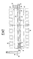
- a conveyor apparatus according to the present invention, generally indicated by the reference numeral 11, comprises a plurality of supporting and conveyor elements of plate type 12, which are suitable for receiving products (not shown in the figures) in order to convey them towards unloading stations, schematically indicated by the reference numerals 10 and longitudinally positioned alongside it.
- Each one of said plate elements 12 is positioned in succession relatively to other similar elements and is positioned integral with a support elements 13, which is positioned transversely to, and fastened to, a pair of chains 14, which chains perform the task of acting as continuous driving elements sliding on vertical planes on complementary guide elements 15 fastened to a framework 16 of the conveyor apparatus.
- a pair of driving sprocket wheels 17, suitably driven by a motor means drives the pair of chains 14 to move; which pair of chains 14 are positioned according to a closed-loop path throughout the longitudinal length of the apparatus and furthermore run around further return sprocket wheels (not shown in the figures as well); and consequently also drives the plurality of transversal support elements 13 to move with them.
- Each one of said plate elements 12 is provided with a downwards extending pin element 18 which is rotatably hinged at 19 on a transversal support element 13.
- the lower free end of this pin element is provided with an appendix, such as, e.g., a ball 20, which is suitable for getting engaged inside a first sliding guide 21 longitudinally provided on the framework of the conveyor apparatus and which also is arranged according to a closed-loop path similar to the closed-loop path of the pair of chains 14.
- second sliding guides 22 and 23, also integral with the framework 16 are provided along at least one upper horizontal lead of said conveyor apparatus.
- a plurality of switching elements are provided along said upper horizontal lead, usually lined up with the first sliding guide 21 ( Figure 2).
- Each switching element is constituted by a body 25 which can move to and from on a horizontal plane, and from which a pin 26 extends downwards, with said pin 26 being controlled to rotate by an underlying actuator means 27, such as a pneumatic cylinder.
- the body 25 has a cross section which has an essentially "U"-shape, and its mutually opposite inner walls are provided with small tooth-shaped guides 28, which are parallel to the inner walls and extend from a base wall; said tooth-shaped guides 28 are suitable for slidingly receiving wall elements 29, which are pliable as thin sheets of metals or of plastic materials, and are fastened at one of their ends only by means of rivetings 30 to side walls of the first sliding guide 21 in order to accomplish the continuity of the guide means.
- each one of said switching elements 24 is positioned in correspondence of openings 31 provided through the walls of the first sliding guide 21. From Figure 2, one can observe that by means of the actuator means 27 each switching element 24 can be caused to move to and fro by an angle of about 45° on each side, so as to be moved both in correspondence of a second guide means 22, and of a second guide 23, positioned on both opposite parallel sides of the first central sliding guide 21 ( Figure 2).
- both second sliding guides 22 and 23 are each one provided with stationary, vertical diverting walls 32 positioned inclined in the direction of movement of the conveyor apparatus, and such as to cause the ball 20 of a pin element 18 to be returned towards the first, central sliding guide 21.
- an opening 33 is provided, which is provided with a further pliable wall element 34, also consisting, for example, of a thin sheet of metal, fastened at one single and thereof, by means of rivetings 35, to the inner side walls of the first sliding guide 21.
- the wall element 34 can be plied and opened only if it is pushed by a pin element coming from either of the second sliding guides 22, 23, and which must return into the central sliding guide 21.
- a tilting unit is furthermore provided, which makes it possible also those products, or better those plate elements 12, to be unloaded, which may have not been diverted into the second side sliding guides 22 or 23, owing to an operational fault, or inadvertently in case the preselected and necessary unloading step was so programmed as to take place automatically.
- the tilting unit comprises a diverting wall 36 installed in an inclined position inside the first sliding guide 21; said wall 36 diverts, through a connection opening similar to the connection opening 33, all of the incoming pin elements 18 towards a second sliding guide (in Figure 1: the side sliding guide 23), so that all of said plate elements 12 are obliged to laterally tilt and overturn on that side, thus causing any products which accidentally may have not been unloaded at a prior stage to be unloaded onto an evacuating conveyor means 41, acting as a safety exit for the products.
- a further stationary inclined wall 37 installed inside the second selected sliding guide, in this case the guide 23, returns, through a further connecting opening also similar to the opening 33, all of the pin elements into the central guide 21, so that all of the plate elements 12 will slid, lined up with one another, first running around the sprocket wheels at that apparatus end and then running, upside-down, along the bottom horizontal lead of the closed-loop path of the conveyor apparatus.
- the plate elements 12 should be capable of being tilted and overturned in correspondence of collecting or container elements, mail bags or buffer roll ways, as hereinabove schematically represented as unloading stations 10.
- the operator sets, by means of electrical connecting lines 39, the desired unloading sequence, so that the tilting and the overturning of a predetermined plate element can take place towards the preselected unloading station 10.
- sensor means 40 such as, e.g., photo-cells, optical readers or magnetic sensors
Landscapes
- Engineering & Computer Science (AREA)
- Mechanical Engineering (AREA)
- Branching, Merging, And Special Transfer Between Conveyors (AREA)
- Veneer Processing And Manufacture Of Plywood (AREA)
- Attitude Control For Articles On Conveyors (AREA)
- Discharge Of Articles From Conveyors (AREA)
- Framework For Endless Conveyors (AREA)
- Dry Formation Of Fiberboard And The Like (AREA)
- Chemical And Physical Treatments For Wood And The Like (AREA)
- Devices For Post-Treatments, Processing, Supply, Discharge, And Other Processes (AREA)
- Preparation Of Clay, And Manufacture Of Mixtures Containing Clay Or Cement (AREA)
Priority Applications (1)
| Application Number | Priority Date | Filing Date | Title |
|---|---|---|---|
| AT89201158T ATE87881T1 (de) | 1988-05-09 | 1989-05-05 | Zusammengesetzte foerdereinrichtung, versehen mit seitlich neigbaren platten. |
Applications Claiming Priority (2)
| Application Number | Priority Date | Filing Date | Title |
|---|---|---|---|
| IT2050588 | 1988-05-09 | ||
| IT20505/88A IT1217534B (it) | 1988-05-09 | 1988-05-09 | Trasportatore composito ad elementi a piastra inclinabili lateralmente |
Publications (3)
| Publication Number | Publication Date |
|---|---|
| EP0341789A2 true EP0341789A2 (fr) | 1989-11-15 |
| EP0341789A3 EP0341789A3 (en) | 1990-02-28 |
| EP0341789B1 EP0341789B1 (fr) | 1993-04-07 |
Family
ID=11167946
Family Applications (1)
| Application Number | Title | Priority Date | Filing Date |
|---|---|---|---|
| EP89201158A Expired - Lifetime EP0341789B1 (fr) | 1988-05-09 | 1989-05-05 | Appareil avec convoyeur composé équipé d'éléments plats latéralement inclinables |
Country Status (8)
| Country | Link |
|---|---|
| US (1) | US4989719A (fr) |
| EP (1) | EP0341789B1 (fr) |
| JP (1) | JP3053189B2 (fr) |
| AT (1) | ATE87881T1 (fr) |
| CA (1) | CA1314510C (fr) |
| DE (1) | DE68905857T2 (fr) |
| ES (1) | ES2039832T3 (fr) |
| IT (1) | IT1217534B (fr) |
Cited By (4)
| Publication number | Priority date | Publication date | Assignee | Title |
|---|---|---|---|---|
| EP0664262A1 (fr) * | 1994-01-25 | 1995-07-26 | Bernhard Beumer Maschinenfabrik KG | Elément de transport basculant pour transporteur d'articles (trieuse) |
| WO2012125026A1 (fr) * | 2011-03-14 | 2012-09-20 | Fps Food Processing Systems B.V. | Appareil pour le tri de produits |
| IT201900003931A1 (it) | 2019-03-19 | 2020-09-19 | Sitma Machinery S P A | Metodo e sistema per formare una fila ordinata di prodotti. |
| IT201900007210A1 (it) | 2019-05-24 | 2020-11-24 | Sitma Machinery S P A | Trasportatore a vassoi inclinabili lateralmente. |
Families Citing this family (7)
| Publication number | Priority date | Publication date | Assignee | Title |
|---|---|---|---|---|
| ES2159894T3 (es) | 1996-12-09 | 2001-10-16 | Atecs Mannesmann Ag | Dispositivo de vuelco para el vaciado de recipientes de articulos en piezas |
| DE19755474C1 (de) | 1997-12-02 | 1999-02-11 | Mannesmann Ag | Förderer für die Sortierung von Stückgut |
| US6311848B1 (en) * | 1998-11-18 | 2001-11-06 | Fernando Juan Zenzerovich | Actuator device for tilt ejectors of fruit forming part of an arrangement for classification of fruit |
| US10730078B2 (en) | 2015-12-04 | 2020-08-04 | Berkshire Grey, Inc. | Systems and methods for dynamic sortation of objects |
| CA3007359C (fr) | 2015-12-04 | 2023-03-21 | Berkshire Grey, Inc. | Systemes et procedes permettant un traitement dynamique d'objets |
| CN118973724A (zh) | 2022-04-06 | 2024-11-15 | 伯克希尔格雷营业股份有限公司 | 具有多物体穿梭的物体处理系统和方法 |
| GB2632531A (en) * | 2024-05-07 | 2025-02-12 | Betan Ltd | Support assembly |
Family Cites Families (9)
| Publication number | Priority date | Publication date | Assignee | Title |
|---|---|---|---|---|
| US3589501A (en) * | 1969-04-16 | 1971-06-29 | Spra Con Co The | Article carrying and discharge mechanisms |
| US3669245A (en) * | 1970-01-13 | 1972-06-13 | Aerojet General Co | Tilt type conveyors |
| DE2037380C3 (de) * | 1970-07-21 | 1974-05-22 | Mannesmann-Geisel Gmbh & Co, 6800 Mannheim | Verteilförderanlage mit kippbaren Plattformen |
| US3662874A (en) * | 1970-10-12 | 1972-05-16 | Butz Engineering Co | Parcel sorting conveyor system |
| DK540277A (da) * | 1976-12-13 | 1978-06-14 | American Chain & Cable Co | Transportoersystem |
| DE2729724A1 (de) * | 1977-07-01 | 1979-01-04 | Beumer Maschf Bernhard | Foerdervorrichtung |
| US4378062A (en) * | 1978-10-30 | 1983-03-29 | Acco Industries Inc. | Tilting carrier system |
| SU965916A1 (ru) * | 1979-06-25 | 1982-10-15 | Ростовский-На-Дону Институт Сельскохозяйственного Машиностроения | Устройство дл автоматического выбора направлени перемещени подвижного объекта |
| JPS60236922A (ja) * | 1984-05-07 | 1985-11-25 | Daifuku Co Ltd | 仕分け用トレ−コンベヤ |
-
1988
- 1988-05-09 IT IT20505/88A patent/IT1217534B/it active
-
1989
- 1989-05-05 EP EP89201158A patent/EP0341789B1/fr not_active Expired - Lifetime
- 1989-05-05 ES ES198989201158T patent/ES2039832T3/es not_active Expired - Lifetime
- 1989-05-05 DE DE89201158T patent/DE68905857T2/de not_active Expired - Fee Related
- 1989-05-05 AT AT89201158T patent/ATE87881T1/de not_active IP Right Cessation
- 1989-05-08 US US07/348,988 patent/US4989719A/en not_active Expired - Lifetime
- 1989-05-09 CA CA000599130A patent/CA1314510C/fr not_active Expired - Lifetime
- 1989-05-09 JP JP1115907A patent/JP3053189B2/ja not_active Expired - Lifetime
Cited By (4)
| Publication number | Priority date | Publication date | Assignee | Title |
|---|---|---|---|---|
| EP0664262A1 (fr) * | 1994-01-25 | 1995-07-26 | Bernhard Beumer Maschinenfabrik KG | Elément de transport basculant pour transporteur d'articles (trieuse) |
| WO2012125026A1 (fr) * | 2011-03-14 | 2012-09-20 | Fps Food Processing Systems B.V. | Appareil pour le tri de produits |
| IT201900003931A1 (it) | 2019-03-19 | 2020-09-19 | Sitma Machinery S P A | Metodo e sistema per formare una fila ordinata di prodotti. |
| IT201900007210A1 (it) | 2019-05-24 | 2020-11-24 | Sitma Machinery S P A | Trasportatore a vassoi inclinabili lateralmente. |
Also Published As
| Publication number | Publication date |
|---|---|
| US4989719A (en) | 1991-02-05 |
| CA1314510C (fr) | 1993-03-16 |
| EP0341789A3 (en) | 1990-02-28 |
| JPH02147514A (ja) | 1990-06-06 |
| IT8820505A0 (it) | 1988-05-09 |
| DE68905857D1 (de) | 1993-05-13 |
| IT1217534B (it) | 1990-03-30 |
| EP0341789B1 (fr) | 1993-04-07 |
| ES2039832T3 (es) | 1993-10-01 |
| ATE87881T1 (de) | 1993-04-15 |
| JP3053189B2 (ja) | 2000-06-19 |
| DE68905857T2 (de) | 1993-10-07 |
Similar Documents
| Publication | Publication Date | Title |
|---|---|---|
| EP0341789B1 (fr) | Appareil avec convoyeur composé équipé d'éléments plats latéralement inclinables | |
| US4040318A (en) | Transfer machine for cutting rolled sheet metal | |
| US4413662A (en) | Edging system | |
| CA2039532C (fr) | Machine de tri de graphiques et/ou d'impression | |
| US4306646A (en) | Conveyor apparatus | |
| US4984677A (en) | Device for transferring objects from a conveyor to a collection device | |
| EP0615925A2 (fr) | Appareil et procédé de chargement d'articles | |
| DE102007040465B3 (de) | Vorrichtung zum Zuführen von Wäschestücken zu einer Wäschebehandlungseinrichtung, insbesondere einer Mangel | |
| EP0626325A1 (fr) | Transporteur | |
| GB2197633A (en) | Apparatus for sorting items | |
| EP0131555A1 (fr) | Palettiseur pour objets, notamment des récipients tels que des sacs et similaires | |
| GB2153772A (en) | Carriage for sorting-machines in particular, with independently actioned tiltable plate | |
| CA2030753A1 (fr) | Machine a gerber | |
| US3770143A (en) | Apparatus for transferring trays between a conveyor system and a stack | |
| US4576536A (en) | Machine for stacking automatically packs of panels of different sizes on respective lifting platforms | |
| US3235101A (en) | Semi-automatic transferring apparatus | |
| EP0636086B1 (fr) | Dispositif d'ensachage de produits | |
| US4141392A (en) | Apparatus for automatic insertion of valved bags on bag-filling machines | |
| EP0080230A1 (fr) | Appareil pour la coupe automatique d'une tôle en plusieurs pièces de dimensions différentes | |
| EP0742165A1 (fr) | Dispositif pour trier des produits | |
| US3430784A (en) | Apparatus for stacking and sorting panels | |
| US5185510A (en) | Installation for cutting a workpiece and method for the control thereof | |
| US4565129A (en) | Device for the automatic pile change at the delivery of a printing | |
| CA1117998A (fr) | Convoyeur vertical | |
| CN113247645B (zh) | 袋装水泥的传送及自动装载系统 |
Legal Events
| Date | Code | Title | Description |
|---|---|---|---|
| PUAI | Public reference made under article 153(3) epc to a published international application that has entered the european phase |
Free format text: ORIGINAL CODE: 0009012 |
|
| AK | Designated contracting states |
Kind code of ref document: A2 Designated state(s): AT BE CH DE ES FR GB GR LI LU NL SE |
|
| PUAL | Search report despatched |
Free format text: ORIGINAL CODE: 0009013 |
|
| AK | Designated contracting states |
Kind code of ref document: A3 Designated state(s): AT BE CH DE ES FR GB GR LI LU NL SE |
|
| RAP1 | Party data changed (applicant data changed or rights of an application transferred) |
Owner name: SITMA S.P.A. |
|
| 17P | Request for examination filed |
Effective date: 19900628 |
|
| 17Q | First examination report despatched |
Effective date: 19920612 |
|
| GRAA | (expected) grant |
Free format text: ORIGINAL CODE: 0009210 |
|
| AK | Designated contracting states |
Kind code of ref document: B1 Designated state(s): AT BE CH DE ES FR GB GR LI LU NL SE |
|
| REF | Corresponds to: |
Ref document number: 87881 Country of ref document: AT Date of ref document: 19930415 Kind code of ref document: T |
|
| REF | Corresponds to: |
Ref document number: 68905857 Country of ref document: DE Date of ref document: 19930513 |
|
| ET | Fr: translation filed | ||
| REG | Reference to a national code |
Ref country code: GR Ref legal event code: FG4A Free format text: 3007648 |
|
| REG | Reference to a national code |
Ref country code: ES Ref legal event code: FG2A Ref document number: 2039832 Country of ref document: ES Kind code of ref document: T3 |
|
| PLBE | No opposition filed within time limit |
Free format text: ORIGINAL CODE: 0009261 |
|
| STAA | Information on the status of an ep patent application or granted ep patent |
Free format text: STATUS: NO OPPOSITION FILED WITHIN TIME LIMIT |
|
| 26N | No opposition filed | ||
| EPTA | Lu: last paid annual fee | ||
| EAL | Se: european patent in force in sweden |
Ref document number: 89201158.6 |
|
| REG | Reference to a national code |
Ref country code: GB Ref legal event code: IF02 |
|
| PGFP | Annual fee paid to national office [announced via postgrant information from national office to epo] |
Ref country code: GR Payment date: 20060413 Year of fee payment: 18 |
|
| PGFP | Annual fee paid to national office [announced via postgrant information from national office to epo] |
Ref country code: DE Payment date: 20060427 Year of fee payment: 18 |
|
| PGFP | Annual fee paid to national office [announced via postgrant information from national office to epo] |
Ref country code: GB Payment date: 20060503 Year of fee payment: 18 Ref country code: NL Payment date: 20060503 Year of fee payment: 18 |
|
| PGFP | Annual fee paid to national office [announced via postgrant information from national office to epo] |
Ref country code: SE Payment date: 20060505 Year of fee payment: 18 |
|
| PGFP | Annual fee paid to national office [announced via postgrant information from national office to epo] |
Ref country code: AT Payment date: 20060511 Year of fee payment: 18 |
|
| PGFP | Annual fee paid to national office [announced via postgrant information from national office to epo] |
Ref country code: FR Payment date: 20060515 Year of fee payment: 18 Ref country code: CH Payment date: 20060515 Year of fee payment: 18 |
|
| PGFP | Annual fee paid to national office [announced via postgrant information from national office to epo] |
Ref country code: LU Payment date: 20060607 Year of fee payment: 18 |
|
| PGFP | Annual fee paid to national office [announced via postgrant information from national office to epo] |
Ref country code: ES Payment date: 20060621 Year of fee payment: 18 |
|
| PGFP | Annual fee paid to national office [announced via postgrant information from national office to epo] |
Ref country code: BE Payment date: 20060712 Year of fee payment: 18 |
|
| BERE | Be: lapsed |
Owner name: *SITMA S.P.A. Effective date: 20070531 |
|
| EUG | Se: european patent has lapsed | ||
| REG | Reference to a national code |
Ref country code: CH Ref legal event code: PL |
|
| GBPC | Gb: european patent ceased through non-payment of renewal fee |
Effective date: 20070505 |
|
| PG25 | Lapsed in a contracting state [announced via postgrant information from national office to epo] |
Ref country code: NL Free format text: LAPSE BECAUSE OF NON-PAYMENT OF DUE FEES Effective date: 20071201 |
|
| NLV4 | Nl: lapsed or anulled due to non-payment of the annual fee |
Effective date: 20071201 |
|
| PG25 | Lapsed in a contracting state [announced via postgrant information from national office to epo] |
Ref country code: LI Free format text: LAPSE BECAUSE OF NON-PAYMENT OF DUE FEES Effective date: 20070531 Ref country code: CH Free format text: LAPSE BECAUSE OF NON-PAYMENT OF DUE FEES Effective date: 20070531 Ref country code: AT Free format text: LAPSE BECAUSE OF NON-PAYMENT OF DUE FEES Effective date: 20070505 |
|
| REG | Reference to a national code |
Ref country code: FR Ref legal event code: ST Effective date: 20080131 |
|
| PG25 | Lapsed in a contracting state [announced via postgrant information from national office to epo] |
Ref country code: BE Free format text: LAPSE BECAUSE OF NON-PAYMENT OF DUE FEES Effective date: 20070531 |
|
| PG25 | Lapsed in a contracting state [announced via postgrant information from national office to epo] |
Ref country code: DE Free format text: LAPSE BECAUSE OF NON-PAYMENT OF DUE FEES Effective date: 20071201 |
|
| PG25 | Lapsed in a contracting state [announced via postgrant information from national office to epo] |
Ref country code: GB Free format text: LAPSE BECAUSE OF NON-PAYMENT OF DUE FEES Effective date: 20070505 |
|
| PG25 | Lapsed in a contracting state [announced via postgrant information from national office to epo] |
Ref country code: SE Free format text: LAPSE BECAUSE OF NON-PAYMENT OF DUE FEES Effective date: 20070506 |
|
| PG25 | Lapsed in a contracting state [announced via postgrant information from national office to epo] |
Ref country code: FR Free format text: LAPSE BECAUSE OF NON-PAYMENT OF DUE FEES Effective date: 20070531 |
|
| REG | Reference to a national code |
Ref country code: ES Ref legal event code: FD2A Effective date: 20070507 |
|
| PG25 | Lapsed in a contracting state [announced via postgrant information from national office to epo] |
Ref country code: ES Free format text: LAPSE BECAUSE OF NON-PAYMENT OF DUE FEES Effective date: 20070507 Ref country code: GR Free format text: LAPSE BECAUSE OF NON-PAYMENT OF DUE FEES Effective date: 20071204 |
|
| PG25 | Lapsed in a contracting state [announced via postgrant information from national office to epo] |
Ref country code: LU Free format text: LAPSE BECAUSE OF NON-PAYMENT OF DUE FEES Effective date: 20070505 |