EP0341683A2 - Headrest for motor vehicle seats - Google Patents
Headrest for motor vehicle seats Download PDFInfo
- Publication number
- EP0341683A2 EP0341683A2 EP89108382A EP89108382A EP0341683A2 EP 0341683 A2 EP0341683 A2 EP 0341683A2 EP 89108382 A EP89108382 A EP 89108382A EP 89108382 A EP89108382 A EP 89108382A EP 0341683 A2 EP0341683 A2 EP 0341683A2
- Authority
- EP
- European Patent Office
- Prior art keywords
- ribs
- insertion slot
- headrest
- cushion
- support
- Prior art date
- Legal status (The legal status is an assumption and is not a legal conclusion. Google has not performed a legal analysis and makes no representation as to the accuracy of the status listed.)
- Granted
Links
Images

Classifications
-
- B—PERFORMING OPERATIONS; TRANSPORTING
- B60—VEHICLES IN GENERAL
- B60N—SEATS SPECIALLY ADAPTED FOR VEHICLES; VEHICLE PASSENGER ACCOMMODATION NOT OTHERWISE PROVIDED FOR
- B60N2/00—Seats specially adapted for vehicles; Arrangement or mounting of seats in vehicles
- B60N2/80—Head-rests
Definitions
- the invention relates to a headrest for motor vehicle seats, as described in the unpublished DE patent application P 37 11 498.
- a U-profile hollow rail surrounds the cushion approximately in an equatorial manner over its entire circumference and serves, as it were, as a coupling element for two cover edges on the reference side, each of which carries ring segment-like edge strips arranged into a ring.
- the ring segment-like edge strips are provided with hook elements which snap into the bottom locking holes of the U-profile hollow rail.
- the U-profile hollow rail according to DE patent application P 37 11 498 consists of a relatively ver Rigid, tough plastic, for example made of polyamide, while the cushion support in the event of an impact is made of more easily deformable plastic, for example made of polyethylene.
- the transverse forces acting on the side walls or side wall parts of the U-profile hollow rail are relatively large because the elastically flexible cushion is held under tension by the latter after application of the cover material.
- the invention has for its object to provide a headrest with less manufacturing and assembly costs, which also a tight, essentially seamless joint in practical use even with relatively large upholstery tensions guaranteed in the area of the insertion slot. This object has been achieved in accordance with the characterizing part of patent claim 1.
- the regions delimiting the insertion slot are integrally formed on the cushion carrier.
- the side walls or side wall parts or, if applicable, the bottom of the insertion slot are therefore integral components of a uniform plastic injection molded body. Since this plastic injection molded body also with the same material it has shaped abutments, which support the walls or wall parts, for example in the form of ribs, against the transverse forces introduced by the edge strips in the direction of the slot width, the upholstery carrier can, as previously, be made from more easily deformable, energy-consuming plastic, for example from polyethylene. As a result, the side walls or side wall parts cannot move apart even at higher passenger compartment temperatures in the sense of widening the insertion slot, combined with unsightly coarse gaps between the reference edges. The abutments prevent this disadvantage.
- pressure abutments are formed in that outside of the insertion slot, namely on the outside of the ribs, transverse support ribs or support beads, which extend transversely to these, are formed integrally with the cushion support.
- tension abutments can consist in the fact that in the deepest part of the insertion slot, that is to say at a distance from the free edges of the ribs, the latter are provided in the transverse direction, connecting material ribs which are uniformly connected to one another with respect to the circumference of the padded body.
- the headrest for motor vehicle seats is generally designated by reference number 10.
- the headrest 10 in the form shown is a padded body, which contains a supporting frame, a cushion support 11, which forms a cohesive plastic injection molded part, for example made of polyethylene.
- the cushion support 11 is designed as a frame for a headrest 10 having a central viewing opening.
- the cushion support 11 forms an articulated, channel-like profile with a profile bottom 12 and two outer webs 13, 14.
- two side wall ribs 15, 16 protrude from it.
- the inner surfaces of the side wall ribs 15, 16 form between them an insertion slot 17 for covering edges 18 with internally sewn-on edge strips 19 which have an elongated rectangular cross section, each for example approximately 1 mm thick and approximately 10-15 mm wide, and which, together with the covering edges 18, avoid one Lock the assembly joint to each other or block each other.
- the summed transverse widths or material thicknesses of the two coating edges 18 and the two edge strips 19 are somewhat larger than the transverse width of the insertion slot 17, which is denoted by s.
- the insertion slot 17 is dimensionally stable in that, on the one hand, tension abutments arranged between the two side wall ribs 15, 16 are provided in the form of transverse ribs 20 connected with the same material.
- the transverse ribs 20 follow one another at intervals with respect to the circumference of the headrest 10.
- the outwardly facing narrow surface 21 of the transverse rib 20 extends concavely in the longitudinal direction of the ribs and is also at a distance from the Free rounded edges 22 of the side wall ribs 15, 16 are moved back inwards, so that there is a slot depth required for receiving the reference edges 18 with edge strips 19.
- support ribs 23, 24 are provided between the latter and the outer webs 13, 14, the narrow surfaces 25 of which face outward and also extend concavely in the longitudinal direction of the ribs.
- These support ribs which can set up very high on the side wall ribs 15, 16 thanks to their concave contouring, support the side wall ribs 15, 16 particularly effectively.
- the concave rib contouring also creates a sufficiently large receiving space for the upholstery body.
- support beads 28, 29 are provided as pressure abutments, which extend outside along the side wall ribs 15, 16.
- the otherwise smooth-surface roof or apex wall 30 of the cushion support 11 also forms a bottom 27 of the insertion slot 17, which is provided with locking holes 26 (openings) for receiving locking hooks of the skirting boards according to DE patent application P 37 11 498.
- locking holes 26 openings
- the insertion slot 17 surrounds the headrest 10 approximately in an equatorial manner.
- the invention need not be limited to a frame headrest; rather, the invention is also applicable to fully upholstered headrests.
Landscapes
- Engineering & Computer Science (AREA)
- Aviation & Aerospace Engineering (AREA)
- Transportation (AREA)
- Mechanical Engineering (AREA)
- Seats For Vehicles (AREA)
- Fittings On The Vehicle Exterior For Carrying Loads, And Devices For Holding Or Mounting Articles (AREA)
- Rear-View Mirror Devices That Are Mounted On The Exterior Of The Vehicle (AREA)
- Chair Legs, Seat Parts, And Backrests (AREA)
- Passenger Equipment (AREA)
Abstract
Eine Kopfstütze (10) für Kraftfahrzeugsitze ist mit einem gepolsterten Körper (P), mit einem darin enthaltenen Polsterträger (11), mit einem den Polsterträger (11) umgebenden, einen Polsterüberzug (B) aufweisenden Polster sowie mit einem in den gepolsterten Körper (P) eingelassenen und diesen etwa äquatorartig umringenden etwa radial nach außen offenen Einsteckschlitz (17) versehen. Innerhalb des Einsteckschlitzes (17) sind zur Verbindung von zwei das Polster ringförmig umgebenden Überzugsrändern (18) an letztere befestigte Randleisten (19) gehalten. Hierbei ist der Einsteckschlitz (17) seitlich von zwei etwa im Parallelabstand voneinander angeordneten, mit ihren freien Kanten (22) etwa radial nach außen weisenden Wänden bzw. Wandteilen (15, 16) gebildet.A headrest (10) for motor vehicle seats is provided with a padded body (P), with a cushion carrier (11) contained therein, with a cushion surrounding the cushion carrier (11) and with a cushion cover (B), and with a cushion body (P ) inserted and this approximately equatorial surrounding radially open insertion slot (17). Within the insertion slot (17) for connecting two covering edges (18) which surround the cushion in an annular manner, edge strips (19) attached to the latter are held. Here, the insertion slot (17) is formed laterally by two walls or wall parts (15, 16) which are arranged approximately at a parallel distance from one another and have their free edges (22) pointing approximately radially outwards.
Die den Einsteckschlitz (17) begrenzenden Bereiche (15, 16) (z.B. Wände bzw. die Wandteile) sind unmittelbare werkstoffeinheitliche Bestandteile des Polsterträgers (11), denen mit dem Polsterträger (11) werkstoffeinheitlich verbundene Widerlager (20) zugeordnet sind, welche die durch die Randleisten (19) in Richtung der Schlitzweite (s) eingeleiteten Querkräfte aufnehmen.The areas (15, 16) delimiting the insertion slot (17) (e.g. walls or the wall parts) are direct material-uniform components of the upholstery support (11), which are associated with the upholstery support (20) which is connected to the upholstery support (11) and which are connected by the the edge strips (19) absorb transverse forces introduced in the direction of the slot width (s).
Es wurde eine herstellungs- und montagegünstige Kopfstütze (10) geschaffen, bei der ein Auseinanderklaffen der Montagefuge (17) zwischen den Bezugsrändern (18) vermieden ist. 
Description
Die Erfindung betrifft eine Kopfstütze für Kraftfahrzeugsitze, wie sie in der nicht vorveröffentlichten DE-Patentanmeldung P 37 11 498 beschrieben ist.The invention relates to a headrest for motor vehicle seats, as described in the unpublished DE patent application P 37 11 498.
Beim Gegenstand der DE-Patentanmeldung P 37 11 498 umringt eine U-Profil-Hohlschiene das Polster etwa äquatorartig über dessen gesamten Umfang und dient hierbei gewissermaßen als Kupplungselement für zwei bezugsseitige Überzugsränder, von denen jeder zu einem Ring angeordnete ringsegmentartige Randleisten trägt. Die ringsegmentartigen Randleisten sind mit Hakenelementen versehen, welche in bodenseitige Riegellöcher der U-Profil-Hohlschiene einrasten.In the subject of DE patent application P 37 11 498, a U-profile hollow rail surrounds the cushion approximately in an equatorial manner over its entire circumference and serves, as it were, as a coupling element for two cover edges on the reference side, each of which carries ring segment-like edge strips arranged into a ring. The ring segment-like edge strips are provided with hook elements which snap into the bottom locking holes of the U-profile hollow rail.
Zur Erzielung einer dichtschließenden praktisch übergangslosen Fuge in dem durch den Einsteckschlitz geprägten Verbindungsbereich der Überzugsränder ist es wichtig, daß die den Einsteckschlitz begrenzenden Seitenwände bzw. Seitenwandteile nach Herstellung der Steckverbindung - zumal durch den Einfluß relativ hoher sommerlicher Temperaturen in der Fahrgastzelle - nicht quer auseinanderfedern. Es würde sich ansonsten eine unschöne Fuge bilden. Aus diesem Grunde besteht die U-Profil-Hohlschiene gemäß der DE-Patentanmeldung P 37 11 498 aus einem relativ ver formungsfesten zähen Kunststoff, beispielsweise aus Polyamid, während der Polsterträger für den Fall eines Aufpralls aus leichter verformbarem Kunststoff, beispielsweise aus Polyäthylen, besteht. Die auf die Seitenwände bzw. Seitenwandteile der U-Profil-Hohlschiene wirkenden Querkräfte sind relativ groß, weil das elastisch nachgibige Polster nach Aufbringen des Bezugsstoffes von letzterem unter Vorspannung gehalten wird.In order to achieve a tightly closing, practically seamless joint in the connection area of the covering edges characterized by the insertion slot, it is important that the side walls or side wall parts delimiting the insertion slot do not spring apart transversely after the plug connection has been made, especially because of the influence of relatively high summer temperatures in the passenger compartment. Otherwise an unsightly joint would form. For this reason, the U-profile hollow rail according to DE patent application P 37 11 498 consists of a relatively ver Rigid, tough plastic, for example made of polyamide, while the cushion support in the event of an impact is made of more easily deformable plastic, for example made of polyethylene. The transverse forces acting on the side walls or side wall parts of the U-profile hollow rail are relatively large because the elastically flexible cushion is held under tension by the latter after application of the cover material.
Ausgehend von der in der DE-Patentanmeldung P 37 11 498 beschriebenen Kopfstütze, liegt der Erfindung die Aufgabe zugrunde, eine Kopfstütze mit geringerem Herstellungs- und Montageaufwand zu schaffen, die außerdem beim praktischen Einsatz selbst bei relativ großen Bezugsstoffspannungen eine dichte, im wesentlichen übergangslose Fuge im Bereich des Einsteckschlitzes gewährleistet. Diese Aufgabe ist entsprechend dem Kennzeichenteil des Patentanspruchs 1 gelöst worden.Starting from the headrest described in DE patent application P 37 11 498, the invention has for its object to provide a headrest with less manufacturing and assembly costs, which also a tight, essentially seamless joint in practical use even with relatively large upholstery tensions guaranteed in the area of the insertion slot. This object has been achieved in accordance with the characterizing part of patent claim 1.
Entsprechend der Erfindung sind die den Einsteckschlitz begrenzenden Bereiche dem Polsterträger werkstoffeinheitlich angeformt. Die Seitenwände bzw. Seitenwandteile oder gegebenenfalls der Boden des Einsteckschlitzes sind daher integrale Bestandteile eines einheitlichen Kunststoff-Spritzgußkörpers. Da dieser Kunststoff-Spritzgußkörper zudem werkstoffeinheitlich mit ihm geformte Widerlager aufweist, welche die z.B. als Rippen ausgebildeten Wände bzw. Wandteile entgegen den durch die Randleisten in Richtung der Schlitzweite eingeleiteten Querkräften abstützen, kann der Polsterträger wie bisher aus leichter verformbarem energieverzehrenden Kunststoff, beispielsweise aus Polyäthylen, hergestellt werden. Demzufolge können sich die Seitenwände bzw. Seitenwandteile auch nicht bei höheren Fahrgastraum-Temperaturen im Sinne einer Weitung des Einsteckschlitzes, verbunden mit einer unschönen groben Fugenbildung zwischen den Bezugsrändern, auseinanderbewegen. Die Widerlager verhindern diesen Nachteil.According to the invention, the regions delimiting the insertion slot are integrally formed on the cushion carrier. The side walls or side wall parts or, if applicable, the bottom of the insertion slot are therefore integral components of a uniform plastic injection molded body. Since this plastic injection molded body also with the same material it has shaped abutments, which support the walls or wall parts, for example in the form of ribs, against the transverse forces introduced by the edge strips in the direction of the slot width, the upholstery carrier can, as previously, be made from more easily deformable, energy-consuming plastic, for example from polyethylene. As a result, the side walls or side wall parts cannot move apart even at higher passenger compartment temperatures in the sense of widening the insertion slot, combined with unsightly coarse gaps between the reference edges. The abutments prevent this disadvantage.
Entsprechend der Erfindung sind Druckwiderlager dadurch gebildet, daß außerhalb des Einsteckschlitzes, nämlich außen an den Rippen, sich quer zu diesen erstreckende in Umfangsrichtung aufeinanderfolgende Stützrippen oder Stützwülste werkstoffeinheitlich mit dem Polsterträger geformt sind.According to the invention, pressure abutments are formed in that outside of the insertion slot, namely on the outside of the ribs, transverse support ribs or support beads, which extend transversely to these, are formed integrally with the cushion support.
Entsprechend der Erfindung können andererseits Zugwiderlager darin bestehen, daß im Tiefsten des Einsteckschlitzes, also im Abstand von den freien Kanten der Rippen, letztere in Querrichtung werkstoffeinheitlich miteinander verbindende Querrippen bezüglich des Umfanges des gepolsterten Körpers aufeinanderfolgend vorgesehen sind.According to the invention, on the other hand, tension abutments can consist in the fact that in the deepest part of the insertion slot, that is to say at a distance from the free edges of the ribs, the latter are provided in the transverse direction, connecting material ribs which are uniformly connected to one another with respect to the circumference of the padded body.
Auch ist es grundsätzlich möglich, mit Haken versehene Randleisten gemäß der älteren DE-Patentanmeldung P 37 11 498 und entsprechende Riegellöcher innerhalb des Einsteckschlitzes (seitenwand- oder bodenseitig) vorzusehen. Beispielsweise können die Seitenwandrippen unmittelbar von einer von der Sitzlehne weg nach oben weisenden glatten Dach- bzw. Scheitelfläche des Polsterträgers vorragen, während die Riegellöcher z.B. die Dachfläche unmittelbar durchsetzen. Auch könnte die U-Profil-Hohlschiene gemäß der DE-Patentanmeldung P 37 11 498 unter Bildung von rippenartigen Druckwiderlagern werkstoffeinheitlich an den Polsterträger angespritzt sein.It is also fundamentally possible to provide edge strips provided with hooks in accordance with the older German patent application P 37 11 498 and corresponding locking holes within the insertion slot (on the side wall or bottom side). For example, the side wall ribs can protrude directly from a smooth roof or apex surface of the upholstery carrier pointing away from the seat back, while the locking holes e.g. enforce the roof area immediately. The U-profile hollow rail according to DE patent application P 37 11 498 could also be molded onto the cushion carrier using the same material to form rib-like pressure abutments.
Weitere Erfindungsmerkmale ergeben sich aus zusätzlichen Unteransprüchen.Further features of the invention result from additional subclaims.
In den Zeichnungen ist ein bevorzugtes Ausführungsbeispiel entsprechend der Erfindung näher dargestellt, es zeigen:
- Fig. 1 einen unter Weglassung der Haltestangen durch einen rahmenartigen Kopfpolsterträger etwa radial geführten Querschnitt; diesem Querschnitt ist eine mehr schematisch dargestellte Polsterung mit Überzugsstoff (ansonsten nicht in Ansicht gezeigt) zugeordnet,
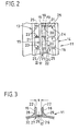
- Fig. 2 unter Weglassung von Polster und Bezugsstoff - lediglich die Überzugsränder und Rand leisten sind gestrichelt dargestellt - eine beidendig abgebrochende Draufsicht auf den Polsterträger, und
- Fig. 3 in grundsätzlicher Anlehnung an die Darstellung gemäß Fig. 1 einen etwas vergrößerten Teilbereich des Einsteckschlitzes mit bodenseitigen Riegellöchern.
- 1 shows a cross section which is guided approximately radially with the omission of the handrails through a frame-like head cushion support; this cross section is associated with a more schematically illustrated upholstery with covering material (otherwise not shown in the view),
- Fig. 2 with omission of upholstery and upholstery fabric - only the cover edges and edge strips are shown in dashed lines - a top view of the upholstery carrier that breaks off at both ends, and
- Fig. 3 in principle based on the illustration of FIG. 1, a slightly enlarged portion of the insertion slot with bolt holes on the bottom.
Die Kopfstütze für Kraftfahrzeugsitze, deren Tragstangen nicht dargestellt sind, ist insgesamt mit der Bezugsziffer 10 bezeichnet.The headrest for motor vehicle seats, the support rods of which are not shown, is generally designated by
Die Kopfstütze 10 stellt in der gezeigten Form einen gepolsterten Körper dar, der als tragendes Gerüst einen Polsterträger 11 enthält, der ein stoffschlüssig zusammenhängendes Kunststoff-Spritzgußteil, beispielsweise aus Polyäthylen, bildet.The
Der Polsterträger 11 ist als Rahmen für eine eine zentrale Durchschauöffnung aufweisende Kopfstütze 10 ausgeführt.The
Der Polsterträger 11 bildet im dargestellten Querschnittbereich ein nach außen geöffnetes gegliedertes rinnenartiges Profil mit einem Profilboden 12 und zwei Außenstegen 13, 14.In the cross-sectional area shown, the cushion support 11 forms an articulated, channel-like profile with a
Werkstoffeinheitlich am Profilboden 12 angeschlossen ragen von diesem zwei Seitenwandrippen 15, 16 vor. Die Innenflächen der Seitenwandrippen 15, 16 bilden zwischen sich einen Einsteckschlitz 17 für Überzugsränder 18 mit innenseitig angenähten Randleisten 19, die langrechteckigen Querschnitt aufweisen, jeweils beispielsweise etwa 1mm dick und etwa 10-15mm breit sind und die sich gemeinsam mit den Überzugsrändern 18 unter Vermeidung einer Montagefuge aneinander verriegeln bzw. sich gegenseitig blockieren.Connected to the
Die summierten Querbreiten bzw. Werkstoffstärken der beiden Überzugsränder 18 und der beiden Randleisten 19 sind etwas größer als die mit s bezeichnete Querweite des Einsteckschlitzes 17.The summed transverse widths or material thicknesses of the two
Der Einsteckschlitz 17 ist dadurch formstabil, daß zum einen zwischen den beiden Seitenwandrippen 15, 16 angeordnete Zugwiderlager in Form von werkstoffeinheitlich angeschlossenen Querrippen 20 vorgesehen sind. Die Querrippen 20 folgen - bezüglich des Umfanges der Kopfstütze 10 - in Abständen aufeinander.The
Die nach außen weisende Schmalfläche 21 der Querrippe 20 erstreckt sich in Rippenlängsrichtung konkav und ist zudem im Abstand von den freien abgerundeten Kanten 22 der Seitenwandrippen 15, 16 nach innen hinein zurückverlagert, so daß sich eine für die Aufnahme der Bezugsränder 18 mit Randleisten 19 erforderliche Schlitztiefe ergibt.The outwardly facing
Beginnend an den Außenseiten der abgerundeten Schmalflächen 22 der Seitenwandrippen 15, 16 sind andererseits zwischen letzteren und den Außenstegen 13, 14 in Druckrichtung belastbare Stützrippen 23, 24 (werkstoffeinheitlich angeformt) vorgesehen, deren nach außen weisende Schmalflächen 25 sich in Rippenlängsrichtung ebenfalls konkav erstrecken. Diese Stützrippen, welche dank ihrer konkaven Konturierung sehr hoch an den Seitenwandrippen 15, 16 ansetzen können, stützen die Seitenwandrippen 15, 16 besonders effektiv ab. Die konkave Rippenkontunierung schafft zudem einen genügend großen Aufnahmeraum für den Polsterkörper.Starting on the outer sides of the rounded
Es ist vorstellbar, daß die Seitenwandrippen 15, 16 - und damit die Weite s des Einsteckschlitzes 17 - durch die als Zugwiderlager wirkenden Querrippen 20 sowie durch die als Stützwiderlager wirkenden Stützrippen 23, 24 gegen starke Querkraftbelastungen stabilisiert sind. Derartige Querkraftbelastungen sind vorhanden, da der Polsterkörper P zur Erzielung eines strammsitzenden Bezuges B unter Vorspannung gehalten ist, während die Bezugsränder 18 mit ihren Randleisten 19 innerhalb des Einsteckschlitzes 17 positioniert sind.It is conceivable that the
In der alternativen Darstellung der Fig. 3 sind als Druckwiderlager Stützwülste 28, 29 vorgesehen, die sich außen entlang der Seitenwandrippen 15, 16 erstrecken. Gemäß Fig. 3 bildet die ansonsten glattflächige Dach- bzw. Scheitelwand 30 des Polsterträgers 11 auch einen Boden 27 des Einsteckschlitzes 17, welcher mit Riegellöchern 26 (Durchbrechungen) zur Aufnahme von Riegelhaken der Randleisten gemäß der DE-Patentanmeldung P 37 11 498 versehen ist. Selbstverständlich ist es auch möglich, die Riegellöcher bei entsprechender Abwandlung der Riegelhaken seitlich innen innerhalb der Seitenwandrippen 15, 16 vorzusehen.In the alternative representation in FIG. 3,
Der Einsteckschlitz 17 umgibt die Kopfstütze 10 etwa äquatorartig.The
Es ist selbstverständlich, daß die Erfindung nicht auf eine Rahmenkopfstütze beschränkt sein muß; vielmehr ist die Erfindung auch bei Vollpolster-Kopfstützen anwendbar.It is understood that the invention need not be limited to a frame headrest; rather, the invention is also applicable to fully upholstered headrests.
Allen Ausführungsformen ist gemeinsam, daß die Höhenlage der freien Kante bzw. Schmalseite 22 jeder Seitenwandrippe 15, 16 zugleich die Höhe und die partielle Kontur des Polsters P bestimmt.All embodiments have in common that the height of the free edge or
Claims (5)
Priority Applications (1)
| Application Number | Priority Date | Filing Date | Title |
|---|---|---|---|
| AT89108382T ATE81999T1 (en) | 1988-05-11 | 1989-05-09 | HEADREST FOR MOTOR VEHICLE SEATS. |
Applications Claiming Priority (2)
| Application Number | Priority Date | Filing Date | Title |
|---|---|---|---|
| DE3816167A DE3816167C1 (en) | 1988-05-11 | 1988-05-11 | |
| DE3816167 | 1988-05-11 |
Publications (3)
| Publication Number | Publication Date |
|---|---|
| EP0341683A2 true EP0341683A2 (en) | 1989-11-15 |
| EP0341683A3 EP0341683A3 (en) | 1990-03-28 |
| EP0341683B1 EP0341683B1 (en) | 1992-11-04 |
Family
ID=6354205
Family Applications (1)
| Application Number | Title | Priority Date | Filing Date |
|---|---|---|---|
| EP19890108382 Expired - Lifetime EP0341683B1 (en) | 1988-05-11 | 1989-05-09 | Headrest for motor vehicle seats |
Country Status (4)
| Country | Link |
|---|---|
| EP (1) | EP0341683B1 (en) |
| AT (1) | ATE81999T1 (en) |
| DE (2) | DE3816167C1 (en) |
| ES (1) | ES2036747T3 (en) |
Cited By (6)
| Publication number | Priority date | Publication date | Assignee | Title |
|---|---|---|---|---|
| FR2666771A1 (en) * | 1990-09-19 | 1992-03-20 | Europ Sieges Automobiles | HEAD SUPPORT IN PARTICULAR FOR VEHICLE SEAT. |
| EP0552038A1 (en) * | 1992-01-16 | 1993-07-21 | General Motors Corporation | Head restraint |
| EP0689956A1 (en) * | 1994-06-29 | 1996-01-03 | PETER BUTZ GmbH & Co Verwaltungs-KG | Upholstered body for headrests, having a cover |
| EP0858926A1 (en) * | 1997-02-18 | 1998-08-19 | Gestind M.B. Manifattura Di Bruzolo S.P.A | Upholstery securing device for motor-vehicle articles such as headrests and the like |
| US6637822B1 (en) * | 2002-05-31 | 2003-10-28 | Tachi-S Co., Ltd. | Garnish arrangement in annular headrest for vehicle seat |
| WO2004018254A1 (en) * | 2002-08-22 | 2004-03-04 | Eagle Ottawa, Llc | Head restraint assembly and method for its manufacturing |
Families Citing this family (4)
| Publication number | Priority date | Publication date | Assignee | Title |
|---|---|---|---|---|
| DE4218967C2 (en) * | 1992-06-10 | 1995-11-16 | Keiper Recaro Gmbh Co | Headrests for vehicle seats |
| DE10135239B4 (en) * | 2001-07-24 | 2013-12-05 | Grammer Aktiengesellschaft | Headrest for motor vehicle seats |
| PL2783910T3 (en) * | 2013-03-26 | 2016-04-29 | Johnson Controls Gmbh | Vehicle seat comprising an integrated headrest and method for manufacturing a vehicle seat |
| DE102024126720A1 (en) * | 2024-09-17 | 2026-03-19 | Grammer Aktiengesellschaft | Upholstery part for motor vehicles |
Family Cites Families (4)
| Publication number | Priority date | Publication date | Assignee | Title |
|---|---|---|---|---|
| FR2236345A5 (en) * | 1973-07-06 | 1975-01-31 | Faure Bertrand | Foam filled seat back for vehicle - ends of covering material attached to strips wedged into channel |
| DE7701279U1 (en) * | 1977-01-18 | 1977-04-28 | Oke Rainer Von Der Heyde & Co, 4531 Lotte | DEVICE FOR THE PROFILE FORMING OF COVERING MATERIAL LAYED IN PARTICULAR WITH FOAM WHEN ITS ADHESIVE TO A COVERING BASE, IN PARTICULAR A FURNITURE BODY |
| DE2928473A1 (en) * | 1979-07-14 | 1981-01-15 | Daimler Benz Ag | Upholstery clip for vehicle seat - is of two U=shaped clamping stirrups, with upper shank having lug to locate in hole in shank underneath |
| DE3711498C1 (en) * | 1987-04-04 | 1988-10-27 | Eugen Otto 4010 Hilden De Butz | Upholstered headrest for car sheet - has U=shaped hollow rails, surrounding centrally headrest cushion, with annular edge strips coupling two surrounding edges |
-
1988
- 1988-05-11 DE DE3816167A patent/DE3816167C1/de not_active Expired
-
1989
- 1989-05-09 AT AT89108382T patent/ATE81999T1/en not_active IP Right Cessation
- 1989-05-09 DE DE8989108382T patent/DE58902596D1/en not_active Expired - Lifetime
- 1989-05-09 ES ES198989108382T patent/ES2036747T3/en not_active Expired - Lifetime
- 1989-05-09 EP EP19890108382 patent/EP0341683B1/en not_active Expired - Lifetime
Cited By (11)
| Publication number | Priority date | Publication date | Assignee | Title |
|---|---|---|---|---|
| FR2666771A1 (en) * | 1990-09-19 | 1992-03-20 | Europ Sieges Automobiles | HEAD SUPPORT IN PARTICULAR FOR VEHICLE SEAT. |
| EP0477075A1 (en) * | 1990-09-19 | 1992-03-25 | Cesa Compagnie Europeenne De Sieges Pour Automobiles | Headrest, particularly for vehicle seats |
| US5165754A (en) * | 1990-09-19 | 1992-11-24 | Cesa-Compagnie Europeenne De Sieges Pour Automobiles | Headrest with closed cell cushion and a covering having an auto formed surface film and overmoulded underlayer |
| EP0552038A1 (en) * | 1992-01-16 | 1993-07-21 | General Motors Corporation | Head restraint |
| US5405190A (en) * | 1992-01-16 | 1995-04-11 | General Motors Corporation | Cover for vehicle head restraint |
| AU661530B2 (en) * | 1992-01-16 | 1995-07-27 | Lear Corporation | Head restraint |
| EP0689956A1 (en) * | 1994-06-29 | 1996-01-03 | PETER BUTZ GmbH & Co Verwaltungs-KG | Upholstered body for headrests, having a cover |
| EP0858926A1 (en) * | 1997-02-18 | 1998-08-19 | Gestind M.B. Manifattura Di Bruzolo S.P.A | Upholstery securing device for motor-vehicle articles such as headrests and the like |
| US6637822B1 (en) * | 2002-05-31 | 2003-10-28 | Tachi-S Co., Ltd. | Garnish arrangement in annular headrest for vehicle seat |
| WO2004018254A1 (en) * | 2002-08-22 | 2004-03-04 | Eagle Ottawa, Llc | Head restraint assembly and method for its manufacturing |
| US6857699B2 (en) | 2002-08-22 | 2005-02-22 | Eagle Ottawa, Llc | Head restraint assembly and method for its manufacturing |
Also Published As
| Publication number | Publication date |
|---|---|
| EP0341683A3 (en) | 1990-03-28 |
| ES2036747T3 (en) | 1993-06-01 |
| DE3816167C1 (en) | 1989-04-20 |
| EP0341683B1 (en) | 1992-11-04 |
| DE58902596D1 (en) | 1992-12-10 |
| ATE81999T1 (en) | 1992-11-15 |
Similar Documents
| Publication | Publication Date | Title |
|---|---|---|
| DE69604846T2 (en) | Carrier and detachable mounting assembly | |
| DE19781303B4 (en) | Upholstery element with a Velcro connection to its cover | |
| DE29822649U1 (en) | Foam part made of polyurethane or the like, in particular for use as a cushioning element in the manufacture of vehicle seats | |
| EP1280675A1 (en) | Sealing system for vehicle window panes | |
| EP0649619A1 (en) | An anchoring strip for an insertion strip for profiling upholstery | |
| EP0726401A1 (en) | Connection between a support and a panel | |
| EP3322614B1 (en) | Clip for securing a seat cover to a foam part of a seat cushion, foaming tool, production arrangement, and method for producing a foam part of a seat cushion | |
| DE69605690T2 (en) | Detachable mounting assembly | |
| EP0876942A2 (en) | Airbag module for a vehicle passenger restraining system | |
| DE3712882C2 (en) | ||
| EP0341683B1 (en) | Headrest for motor vehicle seats | |
| DE10253176A1 (en) | Cover for covering an opening provided in a vehicle seat, especially an access opening to a retaining element for fixing a child seat, comprises two elastic strips which partially overlap or lie flush with each other on facing sides | |
| DE102007032235A1 (en) | Light rail system for transferring heavy loads into a structure | |
| EP1063147A1 (en) | Vehicle steering wheel | |
| DE60026266T2 (en) | Composite component, in particular front panel of a vehicle | |
| DE102007053009B4 (en) | Fastening arrangement for a seat cover, in particular a vehicle seat, and a mounting method | |
| EP0877171B1 (en) | Member made of plastic material | |
| DE102009026727A1 (en) | Fastening device for releasable connection of body trim e.g. decorative strip, with base support i.e. door, of motor vehicle, has latching element arranged at body trim, and locking element for supporting connection of trim and base support | |
| EP0222391A1 (en) | Fixing of balancing weights on a tyred vehicle wheel | |
| DE10029544A1 (en) | Mounting for an interior lining at a vehicle bodywork has a decorative rod to cover the fastening, with a channel to anchor one part of the mounting which has a snap connection to the other mounting part at the bodywork | |
| DE3104628C2 (en) | Headrest for a motor vehicle seat | |
| EP1249362B1 (en) | Method of Manufacturing a Vehicle Seat with a Sensor Mat to Recognize the Seat Occupant as a Person or a Child Seat as well as Vehicle Seat obtained by Such Method | |
| DE3711498C1 (en) | Upholstered headrest for car sheet - has U=shaped hollow rails, surrounding centrally headrest cushion, with annular edge strips coupling two surrounding edges | |
| DE20021190U1 (en) | Arrangement of a panel and a sealing profile | |
| DE60003256T2 (en) | Cladding arrangement for a motor vehicle sheet metal part |
Legal Events
| Date | Code | Title | Description |
|---|---|---|---|
| PUAI | Public reference made under article 153(3) epc to a published international application that has entered the european phase |
Free format text: ORIGINAL CODE: 0009012 |
|
| AK | Designated contracting states |
Kind code of ref document: A2 Designated state(s): AT DE ES FR GB IT SE |
|
| PUAL | Search report despatched |
Free format text: ORIGINAL CODE: 0009013 |
|
| AK | Designated contracting states |
Kind code of ref document: A3 Designated state(s): AT DE ES FR GB IT SE |
|
| 17P | Request for examination filed |
Effective date: 19900307 |
|
| 17Q | First examination report despatched |
Effective date: 19920421 |
|
| ITF | It: translation for a ep patent filed | ||
| GRAA | (expected) grant |
Free format text: ORIGINAL CODE: 0009210 |
|
| AK | Designated contracting states |
Kind code of ref document: B1 Designated state(s): AT DE ES FR GB IT SE |
|
| REF | Corresponds to: |
Ref document number: 81999 Country of ref document: AT Date of ref document: 19921115 Kind code of ref document: T |
|
| GBT | Gb: translation of ep patent filed (gb section 77(6)(a)/1977) | ||
| RAP2 | Party data changed (patent owner data changed or rights of a patent transferred) |
Owner name: PETER BUTZ GMBH & CO VERWALTUNGS-KG |
|
| RIN2 | Information on inventor provided after grant (corrected) |
Free format text: BUTZ, EUGEN OTTO |
|
| REF | Corresponds to: |
Ref document number: 58902596 Country of ref document: DE Date of ref document: 19921210 |
|
| ET | Fr: translation filed | ||
| REG | Reference to a national code |
Ref country code: ES Ref legal event code: FG2A Ref document number: 2036747 Country of ref document: ES Kind code of ref document: T3 |
|
| PLBE | No opposition filed within time limit |
Free format text: ORIGINAL CODE: 0009261 |
|
| STAA | Information on the status of an ep patent application or granted ep patent |
Free format text: STATUS: NO OPPOSITION FILED WITHIN TIME LIMIT |
|
| 26N | No opposition filed | ||
| PGFP | Annual fee paid to national office [announced via postgrant information from national office to epo] |
Ref country code: AT Payment date: 19940520 Year of fee payment: 6 |
|
| PGFP | Annual fee paid to national office [announced via postgrant information from national office to epo] |
Ref country code: SE Payment date: 19940531 Year of fee payment: 6 |
|
| EAL | Se: european patent in force in sweden |
Ref document number: 89108382.6 |
|
| PG25 | Lapsed in a contracting state [announced via postgrant information from national office to epo] |
Ref country code: AT Effective date: 19950509 |
|
| PG25 | Lapsed in a contracting state [announced via postgrant information from national office to epo] |
Ref country code: SE Effective date: 19950510 |
|
| EUG | Se: european patent has lapsed |
Ref document number: 89108382.6 |
|
| REG | Reference to a national code |
Ref country code: GB Ref legal event code: 711B |
|
| REG | Reference to a national code |
Ref country code: FR Ref legal event code: TP |
|
| REG | Reference to a national code |
Ref country code: GB Ref legal event code: 732E |
|
| REG | Reference to a national code |
Ref country code: ES Ref legal event code: PC2A |
|
| REG | Reference to a national code |
Ref country code: GB Ref legal event code: IF02 |
|
| PGFP | Annual fee paid to national office [announced via postgrant information from national office to epo] |
Ref country code: GB Payment date: 20030425 Year of fee payment: 15 |
|
| PG25 | Lapsed in a contracting state [announced via postgrant information from national office to epo] |
Ref country code: GB Free format text: LAPSE BECAUSE OF NON-PAYMENT OF DUE FEES Effective date: 20040509 |
|
| GBPC | Gb: european patent ceased through non-payment of renewal fee |
Effective date: 20040509 |
|
| PG25 | Lapsed in a contracting state [announced via postgrant information from national office to epo] |
Ref country code: IT Free format text: LAPSE BECAUSE OF NON-PAYMENT OF DUE FEES;WARNING: LAPSES OF ITALIAN PATENTS WITH EFFECTIVE DATE BEFORE 2007 MAY HAVE OCCURRED AT ANY TIME BEFORE 2007. THE CORRECT EFFECTIVE DATE MAY BE DIFFERENT FROM THE ONE RECORDED. Effective date: 20050509 |
|
| PGFP | Annual fee paid to national office [announced via postgrant information from national office to epo] |
Ref country code: FR Payment date: 20050519 Year of fee payment: 17 |
|
| PGFP | Annual fee paid to national office [announced via postgrant information from national office to epo] |
Ref country code: ES Payment date: 20050524 Year of fee payment: 17 |
|
| PG25 | Lapsed in a contracting state [announced via postgrant information from national office to epo] |
Ref country code: ES Free format text: LAPSE BECAUSE OF NON-PAYMENT OF DUE FEES Effective date: 20060510 |
|
| REG | Reference to a national code |
Ref country code: FR Ref legal event code: ST Effective date: 20070131 |
|
| PGFP | Annual fee paid to national office [announced via postgrant information from national office to epo] |
Ref country code: DE Payment date: 20070706 Year of fee payment: 19 |
|
| REG | Reference to a national code |
Ref country code: ES Ref legal event code: FD2A Effective date: 20060510 |
|
| PG25 | Lapsed in a contracting state [announced via postgrant information from national office to epo] |
Ref country code: FR Free format text: LAPSE BECAUSE OF NON-PAYMENT OF DUE FEES Effective date: 20060531 |
|
| PG25 | Lapsed in a contracting state [announced via postgrant information from national office to epo] |
Ref country code: DE Free format text: LAPSE BECAUSE OF NON-PAYMENT OF DUE FEES Effective date: 20081202 |