EP0341479A2 - Verfahren und Formwerkzeug zum Herstellen von Formteilen aus einem flüssigen Reaktionsgemisch - Google Patents
Verfahren und Formwerkzeug zum Herstellen von Formteilen aus einem flüssigen Reaktionsgemisch Download PDFInfo
- Publication number
- EP0341479A2 EP0341479A2 EP89107350A EP89107350A EP0341479A2 EP 0341479 A2 EP0341479 A2 EP 0341479A2 EP 89107350 A EP89107350 A EP 89107350A EP 89107350 A EP89107350 A EP 89107350A EP 0341479 A2 EP0341479 A2 EP 0341479A2
- Authority
- EP
- European Patent Office
- Prior art keywords
- mold cavity
- molded part
- parts
- surface portions
- mold
- Prior art date
- Legal status (The legal status is an assumption and is not a legal conclusion. Google has not performed a legal analysis and makes no representation as to the accuracy of the status listed.)
- Withdrawn
Links
- 239000011541 reaction mixture Substances 0.000 title claims description 13
- 238000000465 moulding Methods 0.000 title claims description 12
- 238000000034 method Methods 0.000 title claims description 11
- 239000007788 liquid Substances 0.000 title 1
- 238000004519 manufacturing process Methods 0.000 claims abstract description 7
- 230000009969 flowable effect Effects 0.000 claims abstract description 6
- 239000011248 coating agent Substances 0.000 claims description 8
- 238000000576 coating method Methods 0.000 claims description 8
- PXHVJJICTQNCMI-UHFFFAOYSA-N Nickel Chemical compound [Ni] PXHVJJICTQNCMI-UHFFFAOYSA-N 0.000 claims description 7
- -1 polytetrafluoroethylene Polymers 0.000 claims description 5
- 229920001343 polytetrafluoroethylene Polymers 0.000 claims description 5
- 239000004810 polytetrafluoroethylene Substances 0.000 claims description 5
- VYZAMTAEIAYCRO-UHFFFAOYSA-N Chromium Chemical compound [Cr] VYZAMTAEIAYCRO-UHFFFAOYSA-N 0.000 claims description 4
- 229910052759 nickel Inorganic materials 0.000 claims description 4
- 239000007787 solid Substances 0.000 claims description 3
- 239000000126 substance Substances 0.000 claims description 3
- 239000000919 ceramic Substances 0.000 claims description 2
- 238000005524 ceramic coating Methods 0.000 claims description 2
- 229910052804 chromium Inorganic materials 0.000 claims description 2
- 239000011651 chromium Substances 0.000 claims description 2
- 229920002050 silicone resin Polymers 0.000 claims description 2
- 239000011343 solid material Substances 0.000 claims 1
- 230000003746 surface roughness Effects 0.000 claims 1
- 239000000463 material Substances 0.000 abstract description 3
- 239000007789 gas Substances 0.000 description 5
- 238000010107 reaction injection moulding Methods 0.000 description 2
- 239000004604 Blowing Agent Substances 0.000 description 1
- 239000003795 chemical substances by application Substances 0.000 description 1
- 150000001875 compounds Chemical class 0.000 description 1
- 230000006835 compression Effects 0.000 description 1
- 238000007906 compression Methods 0.000 description 1
- 238000001816 cooling Methods 0.000 description 1
- 238000004090 dissolution Methods 0.000 description 1
- 230000000694 effects Effects 0.000 description 1
- 238000005516 engineering process Methods 0.000 description 1
- 230000017525 heat dissipation Effects 0.000 description 1
- 238000010137 moulding (plastic) Methods 0.000 description 1
- 238000010422 painting Methods 0.000 description 1
- 229920002635 polyurethane Polymers 0.000 description 1
- 239000004814 polyurethane Substances 0.000 description 1
- 238000007711 solidification Methods 0.000 description 1
- 230000008023 solidification Effects 0.000 description 1
Images
Classifications
-
- B—PERFORMING OPERATIONS; TRANSPORTING
- B29—WORKING OF PLASTICS; WORKING OF SUBSTANCES IN A PLASTIC STATE IN GENERAL
- B29C—SHAPING OR JOINING OF PLASTICS; SHAPING OF MATERIAL IN A PLASTIC STATE, NOT OTHERWISE PROVIDED FOR; AFTER-TREATMENT OF THE SHAPED PRODUCTS, e.g. REPAIRING
- B29C33/00—Moulds or cores; Details thereof or accessories therefor
- B29C33/56—Coatings, e.g. enameled or galvanised; Releasing, lubricating or separating agents
-
- B—PERFORMING OPERATIONS; TRANSPORTING
- B29—WORKING OF PLASTICS; WORKING OF SUBSTANCES IN A PLASTIC STATE IN GENERAL
- B29C—SHAPING OR JOINING OF PLASTICS; SHAPING OF MATERIAL IN A PLASTIC STATE, NOT OTHERWISE PROVIDED FOR; AFTER-TREATMENT OF THE SHAPED PRODUCTS, e.g. REPAIRING
- B29C37/00—Component parts, details, accessories or auxiliary operations, not covered by group B29C33/00 or B29C35/00
- B29C37/005—Compensating volume or shape change during moulding, in general
-
- B—PERFORMING OPERATIONS; TRANSPORTING
- B29—WORKING OF PLASTICS; WORKING OF SUBSTANCES IN A PLASTIC STATE IN GENERAL
- B29C—SHAPING OR JOINING OF PLASTICS; SHAPING OF MATERIAL IN A PLASTIC STATE, NOT OTHERWISE PROVIDED FOR; AFTER-TREATMENT OF THE SHAPED PRODUCTS, e.g. REPAIRING
- B29C33/00—Moulds or cores; Details thereof or accessories therefor
- B29C33/42—Moulds or cores; Details thereof or accessories therefor characterised by the shape of the moulding surface, e.g. ribs or grooves
-
- B—PERFORMING OPERATIONS; TRANSPORTING
- B29—WORKING OF PLASTICS; WORKING OF SUBSTANCES IN A PLASTIC STATE IN GENERAL
- B29C—SHAPING OR JOINING OF PLASTICS; SHAPING OF MATERIAL IN A PLASTIC STATE, NOT OTHERWISE PROVIDED FOR; AFTER-TREATMENT OF THE SHAPED PRODUCTS, e.g. REPAIRING
- B29C33/00—Moulds or cores; Details thereof or accessories therefor
- B29C33/56—Coatings, e.g. enameled or galvanised; Releasing, lubricating or separating agents
- B29C33/60—Releasing, lubricating or separating agents
- B29C33/62—Releasing, lubricating or separating agents based on polymers or oligomers
- B29C33/64—Silicone
-
- B—PERFORMING OPERATIONS; TRANSPORTING
- B29—WORKING OF PLASTICS; WORKING OF SUBSTANCES IN A PLASTIC STATE IN GENERAL
- B29C—SHAPING OR JOINING OF PLASTICS; SHAPING OF MATERIAL IN A PLASTIC STATE, NOT OTHERWISE PROVIDED FOR; AFTER-TREATMENT OF THE SHAPED PRODUCTS, e.g. REPAIRING
- B29C67/00—Shaping techniques not covered by groups B29C39/00 - B29C65/00, B29C70/00 or B29C73/00
- B29C67/24—Shaping techniques not covered by groups B29C39/00 - B29C65/00, B29C70/00 or B29C73/00 characterised by the choice of material
- B29C67/246—Moulding high reactive monomers or prepolymers, e.g. by reaction injection moulding [RIM], liquid injection moulding [LIM]
-
- B—PERFORMING OPERATIONS; TRANSPORTING
- B29—WORKING OF PLASTICS; WORKING OF SUBSTANCES IN A PLASTIC STATE IN GENERAL
- B29K—INDEXING SCHEME ASSOCIATED WITH SUBCLASSES B29B, B29C OR B29D, RELATING TO MOULDING MATERIALS OR TO MATERIALS FOR MOULDS, REINFORCEMENTS, FILLERS OR PREFORMED PARTS, e.g. INSERTS
- B29K2995/00—Properties of moulding materials, reinforcements, fillers, preformed parts or moulds
- B29K2995/0003—Properties of moulding materials, reinforcements, fillers, preformed parts or moulds having particular electrical or magnetic properties, e.g. piezoelectric
- B29K2995/0007—Insulating
Definitions
- the invention relates to a method and a mold for the production of moldings with visible surface portions and invisible surface portions present in their intended use, a flowable reaction mixture forming a solid or microcellular substance being introduced into the mold cavity of a mold.
- Molded parts of the type mentioned are generally made from polyurethane reaction materials in RIM (Reaction Injection Molding) processes (US Pat. No. 4,714,579).
- these molded parts are used, for example, in the automotive industry as door side panels, bumpers, fenders, side skirts and the like. When used as intended, they usually have visible surfaces and invisible surfaces or surfaces that are less eye-catching.
- the object is to create a method and a mold with which the sink marks on visible surfaces of molded parts produced from flowable reaction mixtures can be avoided in a simple manner.
- This object is achieved in that the corresponding invisible surface portions of the molded part Wall portions of the mold cavity are set to a lower adhesion to the molded part than the wall portions of the mold cavity corresponding to the visible surface portions of the molded part.
- the lower liability is set by corresponding roughness.
- a particularly advantageous embodiment is that the lower adhesion is set by a permanent coating that reduces the adhesion.
- invisible surface portions is to be understood beyond the actual wording, that is, when used as intended, it does not necessarily have to be invisible surface portions but, if necessary, those that are visible, but where such sink marks do not catch the eye.
- the new mold for the production of moldings with visible surfaces and invisible surface parts made of a solid or microcellular material and forming a flowable reaction mixture when they are used as intended is based on two mold halves enclosing a mold cavity.
- the wall parts of the mold cavity corresponding to the invisible surface portions of the molded part to be manufactured have a lower adhesion to the molded part than the wall parts of the mold cavity corresponding to the visible surface portions of the molded part.
- the different adhesion can already be achieved through different surface properties, in particular roughness of the corresponding wall parts.
- a suitable coating is preferably nickel, chromium, silicone resin, polytetrafluoroethylene, ceramic, and an - optionally porous - nickel, chrome or ceramic coating with embedded polytetrafluoroethylene.
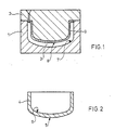
- the mold (Fig. 1) consists of two mold halves 1, 2, which enclose a mold cavity 3.
- the molded part (Fig. 2) is designated 4. It is a side skirt for a motor vehicle.
- This molded part 4 has a visible surface portion 5 and an invisible surface portion 6 after assembly.
- the visible surface portion 5 corresponds to the wall portion 7 of the mold cavity 3, and the remaining wall portion 8 corresponds to the invisible surface portion 6 after the assembly.
- the entire wall portion 7 is located on the mold half 1 and the wall portion 8 on the mold half 2.
- the wall portion 8 shows in this case, a coating 9 made of polytetrafluoroethylene and reducing the adhesion to the hardened molded part 4 and having a thickness of 50 ⁇ m.
Landscapes
- Engineering & Computer Science (AREA)
- Mechanical Engineering (AREA)
- Moulds For Moulding Plastics Or The Like (AREA)
- Injection Moulding Of Plastics Or The Like (AREA)
- Casting Or Compression Moulding Of Plastics Or The Like (AREA)
Abstract
Description
- Die Erfindung betrifft ein Verfahren und ein Formwerkzeug zum Herstellen von Formteilen mit bei deren späterem bestimmungsgemäßen Gebrauch vorhandenen Sichtflächenanteilen und unsichtbaren Oberflächenanteilen, wobei ein Massivstoff oder mikrozellularen Stoff bildendes, fließfähiges Reaktionsgemisch in den Formhohlraum eines Formwerkzeuges eingebracht wird.
- Formteile der genannten Art werden in der Regel aus Polyurethan-Reaktionswerkstoffen in RIM-Verfahren (Reaction-Injection-Moulding) hergestellt (US-PS 4 714 579).
- In entsprechender Gestaltung dienen diese Formteile z.B. in der Automobilindustrie als Türseitenverkleidungen, Stoßfänger, Kotflügel, Seitenschürzen und dergleichen. Bei ihrem bestimmungsgemäßen Gebrauch besitzen sie in der Regel Sichtflächen und unsichtbare Flächen bzw. Flächen, welche optisch weniger ins Auge fallen.
- Ein Problem bei der Herstellung solcher Formteile, insbesondere aus Reaktionsgemischen, welche sich in einem Formwerkzeug ohne Trennmittel verarbeiten lassen, ist das Auftreten von flachen Einfallstellen, sogenannten "sink-marks", an der Oberfläche des Formteils, welche beim Aushärten durch deren Schrumpfung entstehen, indem sich das Formteil lokal von der Formhohlraumwandung ablöst. Bei entsprechendem Blickwinkel fallen solche sinkmarks störend ins Auge. Erfahren solche fehlerhaften Formteile eine Lackierung, so werden diese sink-marks besonders augenfällig.
- Um diese Einfallstellen zu vermeiden, hat man bisher mit "innerem" Nachdruck oder "äußerem" Nachdruck gearbeitet (EP-A 2 206 100 entsprechend US-A-4 714 579). Diese Techniken sind recht aufwendig und haben ihre Grenzen.
- Inneren Nachdruck erzielt man dadurch, daß man das für die Fertigung des Formteils erzeugte Reaktionsgemisch bzw. die dafür verwendeten Reaktionskomponenten mit Gas belädt. Diese eingeschlossenen Gasbläschen stehen wegen der im Verlauf der Aushärtung ansteigenden Reaktionstemperatur unter erhöhtem Druck und wirken der Schwindung entgegen, wodurch die frühzeitige lokale Ablösung des Formteils von der Wandung des Formhohlraumes verhindert wird. Diese Technik hat den Nachteil, daß sie bei Formteilen unter 2,5 mm Wanddicke, bei langen Fließwegen des Reaktionsgemisches im Formwerkzeug, großen Volumenströmen, erhöhter Viskosität des Reaktionsgemisches und kurzen Schußzeiten den Anforderungen nicht mehr gerecht wird, weil ein partielles, unerwünschtes Lösen der Gase im Reaktionsgemisch erfolgt. Bei dünnwandigen Formteilen wird diese Wirkung durch Wärmeableitung in die kühlende Formwerkzeugwand noch verstärkt. Das gelöste und in der plastischen Formmasse fixierte Gas steht dann bei einer Verfestigung des Reaktionsgemisches nicht mehr als Treibmittel zur Erzeugung des inneren Nachdrucks zur Verfügung. Ein ausreichender Nachdruck wird dann nicht aufgebaut. Im übrigen ist auch eine Gasbeladung aus Festigkeitsgründen oft unerwünscht.
- Bei der Technik des äußeren Nachdruckes arbeitet man mit Hilfe eines von außen auf die Füllung des Formhohlraumes ausgeübten Druckes. Die dabei auftretende Kompression kompensiert die schwindungsbedingte Verringerung des Volumens der Reaktionsmasse und verhindert so die Ablösung des Formteils von der Formhohlraumwandung. Die hierfür erforderlichen Werkzeuge und Schließen sind sehr aufwendig. In Anteilen des Formhohlraumes, welche sich parallel zur Schließrichtung des Formwerkzeuges erstrecken, pflanzt sich der aufgebrachte äußere Nachdruck wegen der kritischen Verfestigungscharakteristik des Reaktionsgemisches nur bedingt fort. Deshalb hat diese Technik nur in Sonderfällen Eingang gefunden.
- Es besteht die Aufgabe, ein Verfahren und ein Formwerkzeug zu schaffen, womit man die Einfallstellen auf Sichtflächen von aus fließfähigen Reaktionsgemischen hergestellten Formteilen auf einfache Weise vermeiden kann.
- Diese Aufgabe wird dadurch gelöst, daß die den unsichtbaren Oberflächenanteilen des Formteiles entsprechenden Wandungsanteile des Formhohlraumes auf eine niedrigere Haftung zum Formteil eingestellt werden als die den Sichtflächenanteilen des Formteiles entsprechenden Wandungsanteile des Formhohlraumes.
- Gemäß einer ersten Durchführungsform des neuen Verfahrens erfolgt die Einstellung der niedrigeren Haftung durch entsprechende Rauhigkeit.
- Eine besonders vorteilhafte Durchführungsform besteht darin, daß die Einstellung der niedrigeren Haftung durch eine die Haftung herabsetzende, bleibende Beschichtung erfolgt.
- Durch diese einfachen Maßnahmen wird erreicht, daß sinkmarks auf den Sichtflächen vermieden werden, indem ganz bewußt die Möglichkeit des Entstehens solcher Ablösungserscheinungen auf die bei bestimmungsgemäßen Gebrauch unsichtbaren Oberflächenbereiche verlagert wird, wo sie nicht stören.
- Der Begriff "unsichtbare Oberflächenanteile" ist über den eigentlichen Wortlaut hinausgehend zu verstehen, d.h. es muß sich bei bestimmungsgemäßen Gebrauch nicht unbedingt um unsichtbare Oberflächenanteile handeln, sondern gegebenenfalls um solche, welche zwar sichtbar sind, wo aber solche Einfallstellen nicht ins Auge fallen.
- Das neue Formwerkzeug zum Herstellen von Formteilen mit bei deren späterem bestimmungsgemäßen Gebrauch vorhandenen Sichtflächenanteilen und unsichtbaren Oberflächenanteilen aus einem Massivstoff oder mikrozellularen Stoff bildenden, fließfähigen Reaktionsgemisch geht aus von zwei einen Formhohlraum einschließenden Formwerkzeughälften.
- Das Neue ist darin zu sehen, daß die den unsichtbaren Oberflächenanteilen des zu fertigenden Formteiles entsprechenden Wandungsteile des Formhohlraumes eine niedrigere Haftung zum Formteil aufweisen als die den Sichtflächenanteilen des Formteils entsprechenden Wandungsanteile des Formhohlraumes.
- Die unterschiedliche Haftung läßt sich bereits durch unterschiedliche Oberflächenbeschaffenheit, insbesondere Rauhigkeit der entsprechenden Wandungsteile, erzielen.
- Besonders vorteilhaft ist es, die den unsichtbaren Oberflächenanteilen des Formteiles entsprechenden Wandungsteile des Formhohlraumes mit einer bleibenden, die Haftung herabsetzenden Beschichtung zu versehen.
- Als entsprechende Beschichtung eignen sich vorzugsweise Nickel, Chrom, Siliconharz, Polytetrafluorethylen, Keramik sowie ein - gegebenenfalls poröser - Nickel-, Chrom- oder Keramikbelag mit eingelagertem Polytetrafluorethylen.
- In der Zeichnung ist das neue Formwerkzeug sowie ein damit gefertigtes Formteil rein schematisch im Schnitt dargestellt und nachstehend näher erläutert. Es zeigen:
- Fig. 1 das Formwerkzeug und
- Fig. 2 das Formteil.
- Das Formwerkzeug (Fig. 1) besteht aus zwei Formwerkzeughälften 1, 2, welche einen Formhohlraum 3 einschließen. Das Formteil (Fig. 2) ist mit 4 bezeichnet. Es handelt sich dabei um eine Seitenschürze für ein Kraftfahrzeug. Dieses Formteil 4 weist einen Sichtflächenanteil 5 sowie einen nach der Montage unsichtbaren Oberflächenanteil 6 auf. Dem Sichtflächenanteil 5 entspricht der Wandungsanteil 7 des Formhohlraumes 3, und dem nach der Montage unsichtbaren Oberflächenanteil 6 entspricht der restliche Wandungsanteil 8. Zufälligerweise befindet sich der gesamte Wandungsanteil 7 an der Formwerkzeughälfte 1 und der Wandungsanteil 8 an der Formwerkzeughälfte 2. Der Wandungsanteil 8 weist in diesem Falle eine die Haftung gegenüber dem aushärtenden Formteil 4 herabsetzende Beschichtung 9 aus Polytetrafluorethylen von 50 µm Dicke auf.
Claims (8)
Applications Claiming Priority (2)
| Application Number | Priority Date | Filing Date | Title |
|---|---|---|---|
| DE3815616 | 1988-05-07 | ||
| DE19883815616 DE3815616A1 (de) | 1988-05-07 | 1988-05-07 | Verfahren und formwerkzeug zum herstellen von formteilen aus einem fluessigen reaktionsgemisch |
Publications (2)
| Publication Number | Publication Date |
|---|---|
| EP0341479A2 true EP0341479A2 (de) | 1989-11-15 |
| EP0341479A3 EP0341479A3 (de) | 1990-09-19 |
Family
ID=6353870
Family Applications (1)
| Application Number | Title | Priority Date | Filing Date |
|---|---|---|---|
| EP19890107350 Withdrawn EP0341479A3 (de) | 1988-05-07 | 1989-04-24 | Verfahren und Formwerkzeug zum Herstellen von Formteilen aus einem flüssigen Reaktionsgemisch |
Country Status (3)
| Country | Link |
|---|---|
| EP (1) | EP0341479A3 (de) |
| JP (1) | JPH0216017A (de) |
| DE (1) | DE3815616A1 (de) |
Cited By (3)
| Publication number | Priority date | Publication date | Assignee | Title |
|---|---|---|---|---|
| EP0773093A1 (de) * | 1995-11-08 | 1997-05-14 | Hüls Aktiengesellschaft | Beschichtete Form für die Herstellung von Formteilen aus geschäumten Latex |
| WO2001060591A1 (en) * | 2000-02-15 | 2001-08-23 | Dow Global Technologies Inc. | Mold for reaction injection molding and reaction injection molding process |
| EP1922982A4 (de) * | 2005-09-09 | 2009-11-04 | Olympus Corp | Optisches fensterelement für ein endoskop vom kapseltyp |
Families Citing this family (3)
| Publication number | Priority date | Publication date | Assignee | Title |
|---|---|---|---|---|
| JP2006212924A (ja) * | 2005-02-03 | 2006-08-17 | Toyota Motor Corp | 成形型と樹脂成形方法 |
| DE102011102031A1 (de) * | 2011-05-19 | 2012-11-22 | Faurecia Innenraum Systeme Gmbh | Formwerkzeug, Verfahren zum Verformen eines Bauteils und Formwerkzeug-Einrichtung und Verfahren zum Verbessern der Aufrechterhaltung der In-Situ-Position eines zu formenden Bauteils |
| DE102011087888A1 (de) * | 2011-12-07 | 2013-06-13 | Institut für Polymertechnologien e.V. | Werkzeug und Verfahren zur Herstellung eines Mikroschaumspritzgussteils |
Family Cites Families (4)
| Publication number | Priority date | Publication date | Assignee | Title |
|---|---|---|---|---|
| FR1281768A (fr) * | 1961-02-28 | 1962-01-12 | Siemens Ag | Procédé pour couler sans fissuration une résine moulée dans une cavité, en particulier entre des éléments, par exemple métalliques, disposés l'un à l'intérieur de l'autre |
| DE3137578C2 (de) * | 1981-09-22 | 1984-01-26 | Messerschmitt-Bölkow-Blohm GmbH, 8000 München | Formwerkzeug für die Herstellung von Kunststoffkörpern |
| EP0079860A1 (de) * | 1981-11-16 | 1983-05-25 | Battelle Memorial Institute | Matrizenoberfläche zum Präzisionsformen oder Pressen von Kunststoffen insbesondere für Informationsträger und Verfahren zum Bekleiden dieser Oberfläche |
| NL8401943A (nl) * | 1984-06-19 | 1986-01-16 | Stamicarbon | Werkwijze voor het vervaardigen van een polyamide voorwerp. |
-
1988
- 1988-05-07 DE DE19883815616 patent/DE3815616A1/de not_active Withdrawn
-
1989
- 1989-04-24 EP EP19890107350 patent/EP0341479A3/de not_active Withdrawn
- 1989-05-02 JP JP11225989A patent/JPH0216017A/ja active Pending
Cited By (5)
| Publication number | Priority date | Publication date | Assignee | Title |
|---|---|---|---|---|
| EP0773093A1 (de) * | 1995-11-08 | 1997-05-14 | Hüls Aktiengesellschaft | Beschichtete Form für die Herstellung von Formteilen aus geschäumten Latex |
| WO2001060591A1 (en) * | 2000-02-15 | 2001-08-23 | Dow Global Technologies Inc. | Mold for reaction injection molding and reaction injection molding process |
| US6610239B2 (en) | 2000-02-15 | 2003-08-26 | Dow Global Technologies Inc. | Injection molding process using a coated mold |
| KR100734765B1 (ko) * | 2000-02-15 | 2007-07-06 | 다우 글로벌 테크놀로지스 인크. | 폴리우레탄 제품의 제조방법 |
| EP1922982A4 (de) * | 2005-09-09 | 2009-11-04 | Olympus Corp | Optisches fensterelement für ein endoskop vom kapseltyp |
Also Published As
| Publication number | Publication date |
|---|---|
| JPH0216017A (ja) | 1990-01-19 |
| EP0341479A3 (de) | 1990-09-19 |
| DE3815616A1 (de) | 1989-11-16 |
Similar Documents
| Publication | Publication Date | Title |
|---|---|---|
| EP0024610B1 (de) | Verfahren zum Füllen von Formwerkzeughohlräumen mit einem Reaktionsgemisch aus mindestens zwei fliessfähigen, einen massiven Kunststoff bildenden Reaktionskomponenten | |
| EP1841579B1 (de) | Verfahren zum formen und beschichten eines substrats | |
| DE69416217T2 (de) | Verfahren zum Herstellen eines dünnen Films | |
| DE69304270T2 (de) | Verfahren und Vorrichtung zum Verbinden von Rohren sowie Rohrverbindung | |
| DE69019753T2 (de) | Verfahren zur verwendung von gashilfe während des giessens von kunststoffgegenständen. | |
| DE69116890T2 (de) | Verfahren zur anwendung von gas zum giessen von kunststoffartikeln um die oberflächequalität zu verbessern | |
| DE102012023608B4 (de) | Verfahren und Vorrichtung zum Herstellen eines Formteils | |
| DE68928202T2 (de) | Spritzgiessverfahren | |
| DE102009006066A1 (de) | Form und Verfahren für die Herstellung zweifarbiger Spritzgussteile | |
| WO2001098052A1 (de) | Verfahren zur herstellung eines hybridteils | |
| WO2004000525A1 (de) | Verfahren und vorrichtung zum spritzgiessen mehrkomponentiger, faserverstärkter formteile | |
| DE69206224T2 (de) | Formen eines verstärkten Kunststoffteiles. | |
| DE69012802T2 (de) | Stabilisatorstange. | |
| WO2007128722A1 (de) | Verfahren zur herstellung eines mehrschichtteiles | |
| DE19940245B4 (de) | Verfahren und Form zur Herstellung von Kunststoffgegenständen mit verminderten Oberflächenfehlern und Anordnung zu deren Anwendung | |
| DE3515927A1 (de) | Spritzgiessvorrichtung und verfahren zur herstellung eines gegenstandes in einer derartigen vorrichtung | |
| DE1929343A1 (de) | Spritzduese zum Einbringen des Treibgases bei der Verarbeitung aller schaumfaehigen Kunststoffe | |
| EP0341479A2 (de) | Verfahren und Formwerkzeug zum Herstellen von Formteilen aus einem flüssigen Reaktionsgemisch | |
| DE2746173A1 (de) | Vorrichtung zur herstellung von bauteilen aus faserverstaerkten kunststoffen | |
| DE69407815T2 (de) | Verfahren zum formen und mit diesem verfahren hergestelltes formteil | |
| DE102005006794B4 (de) | Mehrfachkomponenten-Spritzverfahren zur Bildung eines aus mehreren Komponenten bestehenden Körpers | |
| DE2558406A1 (de) | Verfahren zum herstellen von federnd nachgiebigen gegenstaenden und nach dem verfahren hergestellte gegenstaende | |
| DE10008321A1 (de) | Verfahren und Vorrichtung zur Herstellung eines Kunststoff-Formhohlteiles | |
| EP0295529A2 (de) | Vorrichtung und Verfahren zum Herstellen eines Kunststoff-Verbundteils | |
| DE102016217666A1 (de) | Verfahren zum Spritzgießen eines thermoplastischen Kunststoffbauteils und thermoplastisches Kunststoffbauteil |
Legal Events
| Date | Code | Title | Description |
|---|---|---|---|
| PUAI | Public reference made under article 153(3) epc to a published international application that has entered the european phase |
Free format text: ORIGINAL CODE: 0009012 |
|
| 17P | Request for examination filed |
Effective date: 19890424 |
|
| AK | Designated contracting states |
Kind code of ref document: A2 Designated state(s): DE ES FR GB IT NL SE |
|
| PUAL | Search report despatched |
Free format text: ORIGINAL CODE: 0009013 |
|
| AK | Designated contracting states |
Kind code of ref document: A3 Designated state(s): DE ES FR GB IT NL SE |
|
| STAA | Information on the status of an ep patent application or granted ep patent |
Free format text: STATUS: THE APPLICATION HAS BEEN WITHDRAWN |
|
| 18W | Application withdrawn |
Withdrawal date: 19910302 |
|
| R18W | Application withdrawn (corrected) |
Effective date: 19910302 |