EP0341377A2 - Device for lifting and stacking discs with a central hole punched from strip material - Google Patents
Device for lifting and stacking discs with a central hole punched from strip material Download PDFInfo
- Publication number
- EP0341377A2 EP0341377A2 EP89102206A EP89102206A EP0341377A2 EP 0341377 A2 EP0341377 A2 EP 0341377A2 EP 89102206 A EP89102206 A EP 89102206A EP 89102206 A EP89102206 A EP 89102206A EP 0341377 A2 EP0341377 A2 EP 0341377A2
- Authority
- EP
- European Patent Office
- Prior art keywords
- finger
- sleeve
- cart
- material web
- conveyor belt
- Prior art date
- Legal status (The legal status is an assumption and is not a legal conclusion. Google has not performed a legal analysis and makes no representation as to the accuracy of the status listed.)
- Withdrawn
Links
Images


Classifications
-
- B—PERFORMING OPERATIONS; TRANSPORTING
- B21—MECHANICAL METAL-WORKING WITHOUT ESSENTIALLY REMOVING MATERIAL; PUNCHING METAL
- B21D—WORKING OR PROCESSING OF SHEET METAL OR METAL TUBES, RODS OR PROFILES WITHOUT ESSENTIALLY REMOVING MATERIAL; PUNCHING METAL
- B21D43/00—Feeding, positioning or storing devices combined with, or arranged in, or specially adapted for use in connection with, apparatus for working or processing sheet metal, metal tubes or metal profiles; Associations therewith of cutting devices
- B21D43/20—Storage arrangements; Piling or unpiling
- B21D43/22—Devices for piling sheets
-
- B—PERFORMING OPERATIONS; TRANSPORTING
- B21—MECHANICAL METAL-WORKING WITHOUT ESSENTIALLY REMOVING MATERIAL; PUNCHING METAL
- B21D—WORKING OR PROCESSING OF SHEET METAL OR METAL TUBES, RODS OR PROFILES WITHOUT ESSENTIALLY REMOVING MATERIAL; PUNCHING METAL
- B21D43/00—Feeding, positioning or storing devices combined with, or arranged in, or specially adapted for use in connection with, apparatus for working or processing sheet metal, metal tubes or metal profiles; Associations therewith of cutting devices
- B21D43/02—Advancing work in relation to the stroke of the die or tool
- B21D43/18—Advancing work in relation to the stroke of the die or tool by means in pneumatic or magnetic engagement with the work
-
- B—PERFORMING OPERATIONS; TRANSPORTING
- B65—CONVEYING; PACKING; STORING; HANDLING THIN OR FILAMENTARY MATERIAL
- B65G—TRANSPORT OR STORAGE DEVICES, e.g. CONVEYORS FOR LOADING OR TIPPING, SHOP CONVEYOR SYSTEMS OR PNEUMATIC TUBE CONVEYORS
- B65G61/00—Use of pick-up or transfer devices or of manipulators for stacking or de-stacking articles not otherwise provided for
-
- B—PERFORMING OPERATIONS; TRANSPORTING
- B65—CONVEYING; PACKING; STORING; HANDLING THIN OR FILAMENTARY MATERIAL
- B65H—HANDLING THIN OR FILAMENTARY MATERIAL, e.g. SHEETS, WEBS, CABLES
- B65H29/00—Delivering or advancing articles from machines; Advancing articles to or into piles
-
- B—PERFORMING OPERATIONS; TRANSPORTING
- B65—CONVEYING; PACKING; STORING; HANDLING THIN OR FILAMENTARY MATERIAL
- B65H—HANDLING THIN OR FILAMENTARY MATERIAL, e.g. SHEETS, WEBS, CABLES
- B65H2301/00—Handling processes for sheets or webs
- B65H2301/40—Type of handling process
- B65H2301/42—Piling, depiling, handling piles
- B65H2301/422—Handling piles, sets or stacks of articles
Definitions
- the invention relates to a receiving and stacking device for e.g. in the case of a cart punching disks punched out of a material web with a central hole.
- Such disks are usually taken out of the material web by hand after punching or, in the case of a so-called break-out device, are pushed through a plunger downwards over a perforated table top.
- the stripping device with the perforated table top does not always work to satisfaction, since the panes may tip over and not fall cleanly on a stack.
- the perforated table top must match the punch pattern exactly, so it must always be adapted to the punch pattern.
- a finger which can be lowered at least so far into the central hole of the disc with its lower end that a radially expandable sleeve lies in the region of the central hole and the disc can be clamped onto it by expanding it and with the Fingers can be raised and released again after the cuff is relaxed.
- the finger can also be inserted through the center hole until the disc sits above the expandable cuff and is prevented from sliding downward after the cuff has expanded.
- the finger according to the invention can therefore first be inserted through the center hole of the disk when the cuff is not expanded.
- the cuff is then expanded to clamp the disc on the cuff or, when the cuff is below the disc, the largest diameter of the cuff is larger than the inside diameter of the center hole of the disc.
- the disc In this expanded state of the cuff, the disc can be lifted up with the finger and placed on a stack.
- the finger can also be placed one after the other on several discs with a center hole in order to lift them up, whereby the cuff is briefly transferred to its unexpanded (relaxed) position shortly before the cuff is inserted through the respective (next) disc in order to pass through the To be able to be pushed through the center hole in order to then be expanded again, so that the pane in question can no longer slide downward.
- the reversible expansion of the cuff can be accomplished by means of a further advantageous feature of the invention in that the finger is connected to a pressure medium supply via which pressure medium e.g. Compressed air, can be fed.
- pressure medium e.g. Compressed air
- the cuff which is made of resilient material, bulges out, so that the disks located above the cuff can be lifted with a finger.
- the discs picked up on the finger can be put down or stripped off. In this way, disks with different center hole size and shape can be excavated with one and the same finger.
- the cuff can, in a further embodiment of the invention, on a radial one that is preferably distributed over the circumference Bores provided sleeve of the finger sit, the interior of which the pressure medium can be fed.
- the radial bores connect the interior of the sleeve which can be pressurized with the inner surface of the sleeve, which can be substantially uniformly bulged all around when the radial bores are distributed over the circumference of the sleeve.
- the radial bores can also open into groove grooves running around the outside of the sleeve.
- the finger can have a rounded cap at its lower end.
- the sleeve is inserted tightly and firmly in the finger, for example between an upper section connected to the pressure medium supply and the lower cap, so that the pressure medium is available for the expansion of the cuff with as little loss as possible.
- a simple assembly of the cuff in the finger is possible in that the sleeve has a thread at its lower end, onto which the cap is screwed. The cuff can then be clamped between said upper portion of the finger and the cap.
- the cuff is preferably supported downwards by the cap in order to maintain a secure position in the finger.
- the finger including the cap is essentially hollow-cylindrical in the area of the cuff and the cuff with an upper and / or lower, preferably tapered edge is received in an inner edge recess of the upper section of the finger or the lower cap and is supported radially outwards.
- the material web that has already been punched and still contains the disks to be picked up is advantageously transferred to a base made of resilient material, such as a soft foam.
- the thickness of the pad is such that the finger, with the cuff relaxed, can be inserted so far through the central hole of the disc to be picked up from the pad by elastic dodging of the underlay material that the cuff is in the area or under that on the top and disc to be picked up comes to rest.
- the finger is height-adjustable and preferably interchangeably attached to the holder of a trolley which can be moved transversely and / or longitudinally to the material web.
- a construction similar to that used for a cart punch can be used, but of a simpler design, since the forces that occur with a punch do not occur.
- the support for the stamped material web can be designed as a conveyor belt running under the movement area of the carriage, which can be moved transversely to the stamped material web.
- the cart can preferably be moved on the upper cross part of a substantially U-shaped machine stand, as is known per se for the cart in a cart punch.
- a further conveyor belt is provided on the side of the base of the stamped material web, which is preferably designed as a conveyor belt, also below the transverse part of the machine stand, for the storage of the disks, which may be combined into a stack.
- this conveyor belt By means of this conveyor belt, the picked up disks can be fed individually or in a stack for further processing or determination.
- a fork-shaped scraper can be arranged above the further conveyor belt, into which the finger can be inserted laterally with a section above the disks held by the expanded sleeve. If the finger is inserted into the scraper after the section has been retracted laterally above the picked-up disks and then pulled up, when the cuff relaxes, the picked-up disks reliably fall down in a stack onto the further conveyor belt.
- the support which is designed as a conveyor belt, for the punched material web is arranged in a continuation of the punching table of an associated punching machine, preferably a cart punching machine.
- the material transport from the punch to the receiving and stacking device according to the invention is short and fast.
- the punched-out perforated disks are fed to the receiving and stacking device in the same sequence or the same pattern as they have been punched out of the material web.
- Material drive an assigned punching machine, preferably cart punching machine, to run, so that all perforated disks punched out of the material web can be immediately lifted and stacked without backing up or unwanted waiting times in the picking and stacking device according to the invention.
- an assigned punching machine preferably cart punching machine
- the movement of the carriage for the finger can be programmable according to any given punching pattern, so that the structure of the pick-up and stacking device according to the invention can be used unchanged for the most varied punching patterns.
- the movement of the cart for the finger can be programmed in the same way as the movement of the cart of an assigned cart punch, so that the fingers for receiving the sheet of material punched out of the material web and transferred onto the base of the receiving and stacking device each takes the right position.
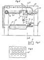
- the receiving and stacking device 61 shown in FIG. 1 can correspond in principle to a cart punch 60 as shown there in addition to the device 61.
- the cart punch 60 has a machine stand 1, on the upper cross part 1 'a guide 1' is provided, along which a cart 2 can run on rollers 3.
- the carriage 2 is driven by a chain and a geared brake motor 5.
- the drive can also be carried out by other elements that are common in mechanical engineering.
- the medium required for the punching stroke is supplied via a flexible feed 7.
- a piston 8 is guided in the cart 2 so that it can move up and down.
- the piston 8 carries a pressure foot 9, on which a knife receiving plate 11 is held with a punch knife 13 via a guide bracket 10.
- the knife receiving plate 11 is secured against displacement by an adjusting screw 12.
- the material web 48 to be punched is guided by transport rollers 36 over a punching table 6 formed by the machine frame 1.
- a piston-cylinder arrangement 35 is formed on the transversely movable carriage 34, to which the required medium is supplied via feeds 47.
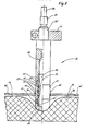
- the piston rod 54 of the piston-cylinder arrangement 35 carries a holder 21 with a vertically downward pointing finger 20, the structure of which is illustrated in detail in FIG. 5
- the finger 20 is interchangeably clamped in the holder 21 at its upper end 20.
- a pressure medium connection 25 connects to a pressure medium supply line 26.
- a pressure medium is guided into the interior 55 of the finger 20 via this.
- a sleeve 22 is tightly and permanently fastened in the finger 20 adjacent to the interior 55.
- the sleeve 22 has radial bores 24 distributed over the circumference, which open into puncture grooves 23 provided in the outer circumference of the sleeve 22.
- the sleeve 22 has at its lower end 22 'a thread for screwing on a cap 64.
- a sleeve 27 made of elastically resilient material, e.g.
- the cuff 27 has an upper and a lower tapered edge 50, 51, which are each received in inner edge recesses 52, 53 of the upper section of the finger 20 or the cap 64 and are supported there in a sealing manner to the outside.
- the middle section of the sleeve 27 between the upper section of the finger 20 and the lower cap 64 forms the outer jacket of the finger 20 in this area.
- the interior 55 of the upper section of the finger 20 is in flow connection with the interior 56 of the rigid sleeve 22, so that at Pressurization via the pressure medium connection 25 Pressure via the radial bores 24 and the puncture grooves 23 is present on the inner surface of the sleeve 27. Under the effect of the pressure, the cuff 27 can expand radially, as indicated on the bulge 28, since its two edges 50 and 51 are clamped airtight between the sleeve 22 and the upper section of the finger 20 or the cap 64.
- the punched material web 48 ' is at this time on the top 46 of the elastic material, for example soft foam, existing pad 30 of such a thickness that the finger 20 by compressing the elastic material so far through the center hole 49th can be passed until the sleeve 27 reaches or lies below the area of the disk 29 to be accommodated.
- the pressure medium supply to the finger 20 is controlled in such a way that the pressure medium escapes from the cuff 27 immediately when the latter is immersed in the center hole 49 of the disk 29 and the pressure medium is supplied again at the lowest point after the finger 20 is immersed, the cuff 27 bulges in order to clamp the disc 29 or to hold it above itself.
- the support 30 designed as a conveyor belt, onto which the punched material web 48 'is transferred runs approximately synchronously with the transport rollers 26 of the cart punch 1. After the disks 29 have been taken out of the material web 48', the remaining material web remainder 48 'is carried away as waste.
- the pick-up and stacking device 61 and the cart punch 60 can be programmed for the most varied but identical punching patterns.
- the number of perforated disk 29 to be accommodated can also be set as desired up to a maximum number.
- the holder 21 is attached with the finger 20 directly to the cart 2 of the cart punch so that it stands above the base 30 and with the drive means provided for the cart 2 is movable.
- the finger 20 can be spatially adjustable relative to the punched image, for example using clamping screws 62. In this way, the punching process starts in the same cycle.
- the trolley 2 can make a separate transverse movement at intervals in order to deposit the respective partial stack arising on the finger 20 until the finger 20 is above the conveyor belt 31.
Abstract
Description
Die Erfindung bezieht sich auf eine Aufnahme- und Stapelvorrichtung für z.B. bei einer Karrenstanze anfallenden aus einer Materialbahn ausgestanzten Scheiben mit Mittelloch.The invention relates to a receiving and stacking device for e.g. in the case of a cart punching disks punched out of a material web with a central hole.
Üblicherweise werden solche Scheiben von Hand nach dem Stanzen aus der Materialbahn genommen oder bei einer sog. Ausbrecheinrichtung über einer gelochten Tischplatte durch Stößel nach unten durchgestoßen. Die Ausbrechvorrichtung mit der gelochten Tischplatte arbeitet nicht immer zur Zufriedenheit, da die Scheiben eventuell abkippen und nicht sauber auf einen Stapel fallen. Außerdem muß die gelochte Tischplatte genau mit dem Stanzbild übereinstimmen, also immer an das Stanzmuster angepaßt werden.Such disks are usually taken out of the material web by hand after punching or, in the case of a so-called break-out device, are pushed through a plunger downwards over a perforated table top. The stripping device with the perforated table top does not always work to satisfaction, since the panes may tip over and not fall cleanly on a stack. In addition, the perforated table top must match the punch pattern exactly, so it must always be adapted to the punch pattern.
Hiervon ausgehend ist es Aufgabe der vorliegenden Erfindung, eine Vorrichtung der gattungsgemäßen Art so auszubilden, daß sie baulich einfach und funktionssicher universeller und daher rationeller einsetzbar ist.Proceeding from this, it is an object of the present invention to design a device of the generic type in such a way that it is structurally simple and functionally reliable and can therefore be used more efficiently.
Diese Aufgabe wird erfindungsgemäß im wesentlichen gelöst durch einen Finger, welcher mit seinem unteren Ende wenigstens so weit in das Mittelloch der Scheibe absenkbar ist, daß eine radial aufweitbare Manschette im Bereich des Mittellochs liegt und die Scheibe durch Aufweiten der Manschette auf dieser festklemmbar und mit dem Finger anhebbar sowie nach dem Entspannen der Manschette wieder freigebbar ist. Der Finger kann auch so weit durch das Mittelloch hindurchgesteckt werden, bis die Scheibe oberhalb der aufweitbaren Manschette sitzt und nach dem Aufweiten der Manschette an dem Abgleiten nach unten gehindert wird.This object is achieved essentially by a finger, which can be lowered at least so far into the central hole of the disc with its lower end that a radially expandable sleeve lies in the region of the central hole and the disc can be clamped onto it by expanding it and with the Fingers can be raised and released again after the cuff is relaxed. The finger can also be inserted through the center hole until the disc sits above the expandable cuff and is prevented from sliding downward after the cuff has expanded.
Der erfindungsgemäße Finger kann also zunächst bei nicht aufgeweiteter Manschette durch das Mittelloch der Scheibe hindurchgesteckt werden. Dann wird die Manschette aufgeweitet, so daß die Scheibe auf der Manschette festgeklemmt wird oder, wenn sich die Manschette unterhalb der Scheibe befindet, der größte Durchmesser der Manschette größer ist als der Innendurchmesser des Mittellochs der Scheibe. In diesem aufgeweiteten Zustand der Manschette kann die Scheibe mittels des Fingers hochgehoben und auf einen Stapel abgesetzt werden. Der Finger kann aber auch nacheinander auf mehrere Scheiben mit Mittelloch aufgesetzt werden, um diese hochzuheben, wobei jeweils kurz vor dem Durchstecken der Manschette durch die jeweilige (nächste) Scheibe die Manschette kurzfristig in ihre nicht aufgeweitete (entspannte) Stellung überführt wird, um durch das Mittelloch hindurch geschoben werden zu können, um dann wieder aufgeweitet zu werden, so daß die betreffende Scheibe nicht mehr nach unten abgleiten kann.The finger according to the invention can therefore first be inserted through the center hole of the disk when the cuff is not expanded. The cuff is then expanded to clamp the disc on the cuff or, when the cuff is below the disc, the largest diameter of the cuff is larger than the inside diameter of the center hole of the disc. In this expanded state of the cuff, the disc can be lifted up with the finger and placed on a stack. The finger can also be placed one after the other on several discs with a center hole in order to lift them up, whereby the cuff is briefly transferred to its unexpanded (relaxed) position shortly before the cuff is inserted through the respective (next) disc in order to pass through the To be able to be pushed through the center hole in order to then be expanded again, so that the pane in question can no longer slide downward.
Die reversible Aufweitung der Manschette kann man mittels eines weiteren vorteilhaften Erfindungsmerkmals dadurch bewerkstelligen, daß der Finger an einer Druckmittelzufuhr angeschlossen ist, über welche dem Innenraum der aus elastischem Material bestehenden Manschette Druckmittel z.B. Druckluft, zuführbar ist. Bei Druckmittelzufuhr baucht sich die Manschette, welche aus elastisch nachgiebigem Material besteht, aus, so daß die über der Manschette befindlichen Scheiben mit dem Finger angehoben werden können. Nach Druckentlastung (Entspannung) der Manschette können die auf dem Finger aufgenommenen Scheiben nach unten abgelegt, bzw. abgestreift werden. Hierdurch können mit ein und demselben Finger Scheiben mit unterschiedlicher Mittellochgröße und -form ausgehoben werden.The reversible expansion of the cuff can be accomplished by means of a further advantageous feature of the invention in that the finger is connected to a pressure medium supply via which pressure medium e.g. Compressed air, can be fed. When pressure medium is supplied, the cuff, which is made of resilient material, bulges out, so that the disks located above the cuff can be lifted with a finger. After relieving pressure (relaxation) of the cuff, the discs picked up on the finger can be put down or stripped off. In this way, disks with different center hole size and shape can be excavated with one and the same finger.
Damit der Finger die erforderliche Stabilität bewahrt, kann die Manschette bei einer weiteren Ausgestaltung der Erfindung auf einer mit vorzugsweise über den Umfang verteilten radialen Bohrungen versehenen Hülse des Fingers sitzen, deren Innenraum das Druckmittel zuführbar ist. Die radialen Bohrungen verbinden dabei den mit Druckmittel beaufschlagbaren Innenraum der Hülse mit der Innenfläche der Manschette, welche bei Verteilung der radialen Bohrungen über den Umfang der Hülse rundum im wesentlichen gleichmäßig bauchig aufgeweitet werden kann.To ensure that the finger maintains the required stability, the cuff can, in a further embodiment of the invention, on a radial one that is preferably distributed over the circumference Bores provided sleeve of the finger sit, the interior of which the pressure medium can be fed. The radial bores connect the interior of the sleeve which can be pressurized with the inner surface of the sleeve, which can be substantially uniformly bulged all around when the radial bores are distributed over the circumference of the sleeve.
Um die Druckbeaufschlagung der Manschette noch weiter zu verbessern, können die radialen Bohrungen auch in auf der Außenseite der Hülse umlaufende Einstichnuten münden.In order to further improve the pressurization of the cuff, the radial bores can also open into groove grooves running around the outside of the sleeve.
Um das Einführen des Fingers in das jeweilige Mittelloch der aufzunehmenden Scheibe zu erleichtern, kann der Finger an seinem unteren Ende eine abgerundete Kappe aufweisen.In order to facilitate the insertion of the finger into the respective center hole of the pane to be picked up, the finger can have a rounded cap at its lower end.
Die Hülse ist in dem Finger, beispielsweise zwischen einem oberen an die Druckmittelzufuhr angeschlossenen Abschnitt und der unteren Kappe, dicht und fest eingesetzt, so daß das Druckmittel möglichst verlustfrei für die Aufweitung der Manschette zur Verfügung steht.The sleeve is inserted tightly and firmly in the finger, for example between an upper section connected to the pressure medium supply and the lower cap, so that the pressure medium is available for the expansion of the cuff with as little loss as possible.
Eine einfache Montage der Manschette in den Finger ist dadurch möglich, daß die Hülse an ihrem unteren Ende ein Gewinde trägt, auf welche die Kappe aufgeschraubt ist. Die Manschette kann dann zwischen dem genannten oberen Abschnitt des Fingers und der Kappe eingespannt sein.A simple assembly of the cuff in the finger is possible in that the sleeve has a thread at its lower end, onto which the cap is screwed. The cuff can then be clamped between said upper portion of the finger and the cap.
Dabei wird die Manschette vorzugsweise von der Kappe nach unten abgestützt, um eine sichere Lage in dem Finger beizubehalten.The cuff is preferably supported downwards by the cap in order to maintain a secure position in the finger.
Ferner ist es von besonderem Vorteil, wenn der Finger einschließlich der Kappe im Bereich der Manschette im wesentlichen hohlzylindrisch ausgebildet ist und die Manschette mit einem oberen und/oder unteren, vorzugsweise verjüngten Rand in eine innere Randvertiefung des oberen Abschnitts des Fingers bzw. der unteren Kappe aufgenommen und nach radial außen abgestützt ist.Furthermore, it is particularly advantageous if the finger including the cap is essentially hollow-cylindrical in the area of the cuff and the cuff with an upper and / or lower, preferably tapered edge is received in an inner edge recess of the upper section of the finger or the lower cap and is supported radially outwards.
Um das Aufnehmen der gelochten Scheiben mit der erfindungsgemäßen Vorrichtung zu erleichtern, wird die schon gestanzte, die aufzunehmenden Scheiben noch enthaltende Materialbahn vorteilhafterweise auf eine Unterlage aus elastisch nachgiebigem Material, wie einem weich eingestellten Schaumstoff, überführt. Die Dicke der Unterlage ist dabei so bemessen, daß der Finger, bei entspannter Manschette, so weit durch das Mittelloch der von der Unterlage aufzunehmenden Scheibe durch elastisches Ausweichen des Unterlagenmaterials hindurchgesteckt werden kann, daß die Manschette im Bereich oder unter der auf der Oberseite abgelegten und aufzunehmenden Scheibe zu liegen kommt.In order to make it easier to pick up the perforated disks with the device according to the invention, the material web that has already been punched and still contains the disks to be picked up is advantageously transferred to a base made of resilient material, such as a soft foam. The thickness of the pad is such that the finger, with the cuff relaxed, can be inserted so far through the central hole of the disc to be picked up from the pad by elastic dodging of the underlay material that the cuff is in the area or under that on the top and disc to be picked up comes to rest.
Um ein weitgehend selbsttätiges Arbeiten der erfindungsgemäßen Aufnahme- und Stapelvorrichtung zu gewährleisten, ist der Finger höhenverstellbar und vorzugsweise auswechselbar an dem Halter eines quer und/oder längs zur Materialbahn verfahrbaren Karrens angebracht. Hierzu kann eine ähnliche Konstruktion dienen, wie sie auch für eine Karrenstanze verwendet wird, jedoch von einfacherer Bauart, da die bei einer Stanze auftretenden Kräfte nicht auftreten.In order to ensure that the receiving and stacking device according to the invention operates largely automatically, the finger is height-adjustable and preferably interchangeably attached to the holder of a trolley which can be moved transversely and / or longitudinally to the material web. For this purpose, a construction similar to that used for a cart punch can be used, but of a simpler design, since the forces that occur with a punch do not occur.
Die Unterlage für die gestanzte Materialbahn kann dabei als unter dem Bewegungsbereich des quer zur gestanzten Materialbahn verfahrbaren Karrens umlaufendes Transportband ausgebildet sein. Dadurch können die aus der gestanzten Materialbahn auszuhebenden gelochten Scheiben durch Vorwärtsbewegung der Materialbahn mittels des Transportbandes nacheinander in den Arbeitsbereich des Karrens und damit des Fingers gebracht werden. Auf diese Weise können bei hohem Durchsatz Finger und Mittelloch auf einfache Weise immer zur Deckung gebracht werden.The support for the stamped material web can be designed as a conveyor belt running under the movement area of the carriage, which can be moved transversely to the stamped material web. As a result, the perforated disks to be lifted out of the punched material web can be brought one after the other into the work area of the cart and thus of the finger by moving the material web forward by means of the conveyor belt. In this way, the fingers and the center hole can always be made to coincide with a high throughput.
Der Karren ist vorzugsweise an dem oberen Querteil eines im wesentlichen U-förmigen Maschinenständers verfahrbar, wie dies für den Karren bei einer Karrenstanze an sich bekannt ist.The cart can preferably be moved on the upper cross part of a substantially U-shaped machine stand, as is known per se for the cart in a cart punch.
Gemäß einer Weiterbildung der Erfindung ist seitlich der vorzugsweise als Transportband ausgebildeten Unterlage der gestanzten Materialbahn, ebenfalls unterhalb des Querteils des Maschinenständers, ein weiteres Transportband für die Ablage der ggf. zu einem Stapel zusammengefaßten Scheiben vorgesehen. Mittels dieses Transportbandes können die aufgenommenen Scheiben im einzelnen oder im Stapel ihrer weiteren Verarbeitung oder Bestimmung zugeführt werden.According to a further development of the invention, a further conveyor belt is provided on the side of the base of the stamped material web, which is preferably designed as a conveyor belt, also below the transverse part of the machine stand, for the storage of the disks, which may be combined into a stack. By means of this conveyor belt, the picked up disks can be fed individually or in a stack for further processing or determination.
Damit die von dem Finger aufgenommenen Scheiben zügig von dem Finger auf das weitere Transportband gelangen, kann oberhalb des weiteren Transportbandes ein gabelförmiger Abstreifer angeordnet sein, in welchen der Finger mit einem Abschnitt oberhalb der von der aufgeweiteten Manschette gehaltenen Scheiben seitlich einfahrbar ist. Wird der Finger nach dem seitlichen Einfahren seines Abschnittes oberhalb der aufgenommenen Scheiben in den Abstreifer eingeführt und dann hochgezogen, fallen bei Entspannung der Manschette, die aufgenommenen Scheiben zuverlässig im Stapel nach unten auf das weitere Transportband.So that the disks picked up by the finger quickly reach the further conveyor belt from the finger, a fork-shaped scraper can be arranged above the further conveyor belt, into which the finger can be inserted laterally with a section above the disks held by the expanded sleeve. If the finger is inserted into the scraper after the section has been retracted laterally above the picked-up disks and then pulled up, when the cuff relaxes, the picked-up disks reliably fall down in a stack onto the further conveyor belt.
Ein weiteres Merkmal der Erfindung besteht darin, daß die als Transportband ausgebildete Unterlage für die gestanzte Materialbahn in Fortsetzung des Stanztisches einer zugeordneten Stanzmaschine, vorzugsweise Karrenstanzmaschine, angeordnet ist. Hierdurch wird der Materialtransport von der Stanze zu der erfindungsgemäßen Aufnahme- und Stapelvorrichtung kurz und schnell. Insbesondere werden die ausgestanzten Lochscheiben der Aufnahme- und Stapelvorrichtung in der gleichen Folge bzw. dem gleichen Muster zugeführt, wie sie aus der Materialbahn ausgestanzt worden sind.Another feature of the invention is that the support, which is designed as a conveyor belt, for the punched material web is arranged in a continuation of the punching table of an associated punching machine, preferably a cart punching machine. As a result, the material transport from the punch to the receiving and stacking device according to the invention is short and fast. In particular, the punched-out perforated disks are fed to the receiving and stacking device in the same sequence or the same pattern as they have been punched out of the material web.
Hierbei ist es zweckmäßig, die als Transportband ausgebildete Unterlage synchron mit den Transportwalzen o.dgl. Materialantrieb einer zugeordneten Stanzmaschine, vorzugsweise Karrenstanzmaschine, laufen zu lassen, so daß alle aus der Materialbahn ausgestanzten Lochscheiben unverzüglich ausgehoben und abgestapelt werden können, ohne daß es einen Rückstau oder unerwünschte Wartezeiten bei der erfindungsgemäßen Aufnahme- und Stapelvorrichtung gibt.It is expedient here or the like designed as a conveyor belt underlay synchronously with the transport rollers. Material drive an assigned punching machine, preferably cart punching machine, to run, so that all perforated disks punched out of the material web can be immediately lifted and stacked without backing up or unwanted waiting times in the picking and stacking device according to the invention.
Die Bewegung des Karrens für den Finger kann nach jedem vorgegebenen Stanzbild programmierbar sein, so daß die erfindungsgemäße Aufnahme- und Stapelvorrichtung in ihrem Aufbau unverändert für die verschiedensten Stanzmuster einsetzbar ist.The movement of the carriage for the finger can be programmable according to any given punching pattern, so that the structure of the pick-up and stacking device according to the invention can be used unchanged for the most varied punching patterns.
Dabei kann insbesondere die Bewegung des Karrens für den Finger in gleicher Weise programmiert sein, wie die Bewegung des Karrens einer zugeordneten Karrenstanze, so daß die Finger für die Aufnahme der aus der Materialbahn ausgestanzten und auf die Unterlage der Aufnahme- und Stapelvorrichtung überführten Materialbahn jeweils die richtige Position einnimmt.In particular, the movement of the cart for the finger can be programmed in the same way as the movement of the cart of an assigned cart punch, so that the fingers for receiving the sheet of material punched out of the material web and transferred onto the base of the receiving and stacking device each takes the right position.
Weitere Ziele, Merkmale, Vorteile und Anwendungsmöglichkeiten der vorliegenden Erfindung ergeben sich aus der nachfolgenden Beschreibung von Ausführungsbeispielen anhand der Zeichnung. Dabei bilden alle beschriebenen und/oder bildlich dargestellten Merkmale für sich oder in beliebiger sinnvoller Kombination den Gegenstand der vorliegenden Erfindung auch unabhängig von ihrer Zusammenfassung in den Ansprüchen oder deren Rückbeziehung.Further objectives, features, advantages and possible uses of the present invention result from the following description of exemplary embodiments with reference to the drawing. All of the described and / or illustrated features, alone or in any meaningful combination, form the subject matter of the present invention, regardless of how they are summarized in the claims or their relationship.
Es zeigen:
- Fig. 1 In Seitenansicht eine die Erfindung aufweisende Aufnahme- und Stapelvorrichtung in Zuordnung zu einer Karrenstanze, jeweils teilweise entlang der Linie I-I von Fig. 2 geschnitten,
- Fig. 2 die Aufnahme- und Stapelvorrichtung nach Fig. 1 aus der Ansicht II von Fig. 2,
- Fig. 3 schematisch in Draufsicht den Abstreifer der Aufnahme- und Stapelvorrichtung von Fig. 2,
- Fig. 4 in Draufsicht einen Abschnitt der Materialbahn nach Aufnahme der ausgestanzten Lochscheiben,
- Fig. 5 teilweise geschnitten, ein Ausführungsbeispiel des Fingers der erfindungsgemäßen Aufnahme- und Stapelvorrichtung, wobei der Finger schon teilweise durch das Mittelloch der aufzunehmenden Scheibe hindurchgeführt ist,
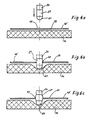
- Fig. 6a bis 6c schematisch in mehreren Stufen den Aufnahmevorgang einer Lochscheibe mit dem erfindungsgemäßen Finger,
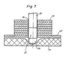
- Fig. 7 schematisch die Aufnahme eines ganzen Stapels von Lochscheiben mit dem erfindungsgemäßen Finger, und
- Fig. 8 in Seitenansicht eine andere die Erfindung aufweisende Ausführungsform, bei welcher Karrenstanze und Aufnahme- und Stapelvorrichtung zu einer Einheit zusammengefaßt sind.
- 1 is a side view of a receiving and stacking device according to the invention in association with a cart punch, partly cut along line II of FIG. 2,
- 2 the pick-up and stacking device according to FIG. 1 from view II of FIG. 2,
- 3 shows a schematic top view of the scraper of the receiving and stacking device from FIG. 2,
- 4 shows a plan view of a section of the material web after the punched-out perforated disks have been received,
- 5 partially cut, an embodiment of the finger of the receiving and stacking device according to the invention, the finger already being partially passed through the center hole of the disc to be picked up,
- 6a to 6c schematically in several stages the recording process of a perforated disc with the finger according to the invention,
- Fig. 7 shows schematically the inclusion of an entire stack of perforated disks with the finger according to the invention, and
- Fig. 8 in side view another embodiment having the invention, in which the cart punch and pick-up and stacking device are combined into one unit.
Die in Fig. 1 dargestellte Aufnahme- und Stapelvorrichtung 61 kann im prinzipiellen Maschinenaufbau einer Karrenstanze 60 entsprechen, wie sie dort neben der Vorrichtung 61 dargestellt ist.The receiving and
Die Karrenstanze 60 hat einen Maschinenständer 1, an dessen oberem Querteil 1′ eine Führung 1˝ vorgesehen ist, entlang welcher ein Karren 2 auf Rollen 3 laufen kann. Der Antrieb des Karrens 2 erfolgt über eine Kette und einen Getriebebremsmotor 5. Der Antrieb kann auch über andere im Maschinenbau übliche Elemente erfolgen. Die Zufuhr des zum Stanzhub erforderlichen Mediums erfolgt über eine biegsame Zuführung 7. Im Karren 2 ist ein Kolben 8 auf- und abbeweglich geführt. An seinem unteren Ende trägt der Kolben 8 einen Druckfuß 9, an welchem eine Messeraufnahmeplatte 11 - mit einem Stanzmesser 13 über Führungswinkel 10 gehalten ist. Gegen Verschieben ist die Messeraufnahmeplatte 11 durch eine Stellschraube 12 gesichert. Die zu stanzende Materialbahn 48 wird von Transportwalzen 36 über einen von dem Maschinengestell 1 gebildeten Stanztisch 6 geführt. Durch die programmgesteuerte Querbewegung des Karrens 2 und die programmgesteuerte Längsbewegung der Materialbahn 48 werden mit einem Mittelloch 49 versehene Scheiben 29 in vorgegebenem Stanzmuster (vgl. Fig. 4) ausgestanzt. Die gestanzte Materialbahn 48′ wird zusammen mit den ausgestanzten Lochscheiben 29 auf eine als Transportband ausgebildete Unterlage 30 überführt. Die Unterlage 30 bildet Teil der Aufnahme- und Stapelvorrichtung 61. Diese hat ähnlich wie die Karrenstanze 60 ein Maschinengestell 41, an dessen oberem Querteil 41′ Führungen 41˝ für die Rollen 43 eines quer zur Unterlage 30 verfahrbaren Karrens 34 vorgesehen sind. Der Antrieb des Karrens 34 erfolgt über einen Getriebebremsmotor 45. Am quer verfahrbaren Karren 34 ist eine Kolben-Zylinder-Anordnung 35 ausgebildet, zu welcher das erforderliche Medium über Zuführungen 47 zugeführt wird. Die Kolbenstange 54 der Kolben-Zylinder-Anordnung 35 trägt einen Halter 21 mit einem senkrecht nach unten weisenden Finger 20, dessen Aufbau in Fig. 5 im einzelnen veranschaulicht istThe
Der Finger 20 ist an seinem oberen Ende 20′ in dem Halter 21 auswechselbar eingeklemmt. An das obere Ende 20′ des Fingers 20 schließt sich ein Druckmittelanschluß 25 mit einer Druckmittelzufuhr-Leitung 26 an. Über diese wird ein Druckmittel in den Innenraum 55 des Fingers 20 geführt. In dem Finger 20 ist in Angrenzung an den Innenraum 55 eine Hülse 22 dicht und dauerhaft befestigt. Die Hülse 22 weist über den Umfang verteilte radiale Bohrungen 24 auf, welche in im Außenumfang der Hülse 22 vorgesehene Einstichnuten 23 münden. Die Hülse 22 hat an ihrem unteren Ende 22′ ein Gewinde für das Aufschrauben einer Kappe 64. In dem Bereich zwischen oberem Abschnitt des Fingers 20 und der Kappe 64 sitzt auf der Hülse 22 eine Manschette 27 aus elastisch nachgiebigem Material, z.B. aus Gummi. Die Manschette 27 hat einen oberen und einen unteren verjüngten Rand 50, 51, welcher jeweils in inneren Randvertiefungen 52, 53 des oberen Abschnitts des Fingers 20 bzw. der Kappe 64 aufgenommen sind und sich dort dichtend nach außen abstützen. Der mittlere Abschnitt der Manschette 27 zwischen oberem Abschnitt des Fingers 20 und unterer Kappe 64 bildet in diesem Bereich den Außenmantel des Fingers 20. Der Innenraum 55 des oberen Abschnitts des Fingers 20 steht mit dem Innenraum 56 der starren Hülse 22 in Strömungsverbindung, so daß bei Druckbeaufschlagung über den Druckmittelanschluß 25 Druck über die radialen Bohrungen 24 und die Einstichnuten 23 auf der Innenfläche der Manschette 27 ansteht. Unter der Wirkung des Druckes kann sich die Manschette 27, wie an der Ausbauchung 28 angedeutet, radial aufweiten, da sie mit ihren beiden Rändern 50 und 51 luftdicht zwischen Hülse 22 und oberem Abschnitt des Fingers 20 bzw. der Kappe 64 eingeklemmt ist.The
Führt man den entsprechend im Durchmesser dimensionierten Finger 20 durch das Mittelloch 49 einer anzuhebenden Scheibe 29 so weit ein, daß die Manschette 27 im Bereich des Mittellochs 49 liegt und beaufschlagt den Finger 20 und damit die- Manschette 27 mit Druckmittel, so weitet sich die Manschette 27 entsprechend der Ausbauchung 28 auf, so daß die Scheibe 29 festgehalten wird und mit dem Finger 20 hochgehoben werden kann (Fig. 6a bis 6c). Entsprechend der Darstellung liegt die gestanzte Materialbahn 48′ zu diesem Zeitpunkt auf der Oberseite 46 der aus elastisch nachgiebigem Material, beispielsweise weich eingestelltem Schaumstoff, bestehenden Unterlage 30 einer solchen Stärke, daß der Finger 20 unter Zusammendrücken des elastisch nachgiebigen Materials so weit durch das Mittelloch 49 hindurchgeführt werden kann, bis die Manschette 27 in den Bereich der aufzunehmenden Scheibe 29 gelangt oder darunter liegt.If the correspondingly dimensioned
Die Druckmittelzufuhr zu dem Finger 20 wird so gesteuert, daß unmittelbar beim Eintauchen desselben in das Mittelloch 49 der Scheibe 29 das Druckmittel aus der Manschette 27 entweichen und nach dem Eintauchen des Fingers 20 im tiefsten Punkt das Druckmittel wieder zugeführt wird, wobei sich die Manschette 27 ausbaucht, um die Scheibe 29 festzuklemmen oder über sich zu halten.The pressure medium supply to the
Auf diese Weise ist es auch möglich, nacheinander viele Scheiben 29 auf dem Finger 20 aufzunehmen. Jeweils beim Eintauchen des Fingers 20 in die nächste Scheibe 29 schiebt sich die vorherige Scheibe 29 etwas nach oben, da in diesem Augenblick die Manschette 27 entspannt ist. Oberhalb der Manschette 27 sind die Scheiben 29 lose auf dem Finger 20 gelagert und ggf. gegen Kippen lose geführt (Fig. 7).In this way, it is also possible to record
Seitlich der Unterlage 30 und unterhalb des Querteils 41′ befindet sich in der Aufnahme- und Stapelvorrichtung 61 ein weiteres Transportband 31 für die Aufnahme und den Abtransport der von dem Finger 20 abgelegten Scheibenstapel. Diese werden abgelegt, indem der Finger 20 mittels des Karrens 34 über das Transportband 31 gefahren und die Manschette 27 entspannt wird. Das Absenken des Scheibenstapels kann dadurch verbessert werden, daß an dem Maschinengestell 41 ein gabelförmiger horizontaler Abstreifer 32 oberhalb des Transportbandes 31 in einer Höhe angebracht ist, daß der Finger 20 mit dem darauf aufgenommenen Scheibenstapel so in den Schlitz eingefahren werden kann, daß sich der Stapel unterhalb des Abstreifers 32 befindet. Wird dann der Finger 20 bei entspannter Manschette 27 hochgezogen, so legt sich der Scheibenstapel auf das Transportband 31 ab.To the side of the
Die als Transportband ausgebildete Unterlage 30, auf welche die gestanzte Materialbahn 48′ überführt wird, läuft etwa synchron mit den Transportwalzen 26 der Karrenstanze 1. Nach der Aufnahme der Scheiben 29 aus der Materialbahn 48′ wird der verbleibende Materialbahnrest 48˝ als Abfall weggeführt.The
Die Aufnahme- und Stapelvorrichtung 61 und die Karrenstanze 60 können für die verschiedensten, aber untereinander gleichen Stanzbilder programmiert werden. Auch die Zahl der aufzunehmenden Lochscheibe 29 kann bis zu einer Höchstzahl beliebig eingestellt werden.The pick-up and stacking
In einer weiteren Ausführungsform der Erfindung, wie sie in Fig. 8 veranschaulicht ist, ist der Halter 21 mit dem Finger 20 unmittelbar am Karren 2 der Karrenstanze so angebracht, daß er über der der Unterlage 30 steht und mit den für den Karren 2 vorgesehenen Antriebsmitteln bewegbar ist. Dabei kann der Finger 20 räumlich gegenüber dem Stanzbild, z.B. über Klemmschrauben 62, verstellbar sein. Auf diese Weise wird im gleichen Takt mit dem Stanzvorgang aufgenommen. Der Karren 2 kann in zeitlichen Abständen zum Absetzen des jeweiligen auf den Finger 20 entstehenden Teilstapels eine gesonderte Querbewegung machen, bis der Finger 20 über dem Transportband 31 steht.In a further embodiment of the invention, as illustrated in FIG. 8, the
- 1 Maschinenständer1 machine stand
- 1′ Querteil1 ′ cross section
- 1˝ Führung1˝ leadership
- 2 Karren2 carts
- 3 Rollen3 rolls
- 5 Getriebebremsmotor5 geared brake motor
- 6 Stanztisch6 punching table
- 7 Zuführung7 feed
- 8 Kolben8 pistons
- 9 Druckfuß9 pressure foot
- 10 Führungswinkel10 guide angles
- 11 Messerentnahmeplatte11 knife removal plate
- 12 Stellschraube12 set screw
- 13 Messer13 knives
- 20 Finger20 fingers
- 20′ Ende20 ′ end
- 21 Halter21 holder
- 22 Hülse22 sleeve
- 22′ Ende22 ′ end
- 23 Einstichnuten23 groove grooves
- 24 Bohrungen24 holes
- 25 Druckmittelanschluß25 pressure medium connection
- 26 Leistung26 performance
- 27 Manschette27 cuff
- 28 Ausbauchung28 bulge
- 29 Scheibe29 disc
- 30 Unterlage30 pad
- 31 Transportband31 conveyor belt
- 32 Abstreifer32 wipers
- 34 Karren34 carts
- 35 Kolben-Zylinder-Anordnung35 piston-cylinder arrangement
- 36 Transportwalzen36 transport rollers
- 41 Maschinenständer41 machine stands
- 41′ Querteil41 ′ cross section
- 41˝ Führung41˝ leadership
- 43 Rollen43 rolls
- 44 Kette44 chain
- 45 Getriebemotor45 geared motor
- 46 Oberseite46 top
- 47 Zuführung47 feeder
- 48 Materialbahn48 material web
- 48′ gestanzte Materialbahn48 ′ stamped material web
- 48˝ Materialbahnrest48˝ material web remnant
- 49 Mittelloch49 center hole
- 50 Rand50 rand
- 51 Rand51 margin
- 52 Vertiefung52 deepening
- 53 Vertiefung53 deepening
- 54 Kolbenstange54 piston rod
- 55 Innenraum55 interior
- 56 Innenraum56 interior
- 60 Karrenstanze60 cart punches
- 61 Aufnahme- und Stapelvorrichtung61 Pick-up and stacking device
- 62 Klemmschrauben62 clamping screws
- 64 Kappe64 cap
Claims (19)
Applications Claiming Priority (2)
| Application Number | Priority Date | Filing Date | Title |
|---|---|---|---|
| DE19883816266 DE3816266A1 (en) | 1988-05-12 | 1988-05-12 | RECEIVING AND STACKING DEVICE FOR FROM A MATERIAL COVER FROM PUNCHED DISC WITH CENTER HOLE |
| DE3816266 | 1988-05-12 |
Publications (2)
| Publication Number | Publication Date |
|---|---|
| EP0341377A2 true EP0341377A2 (en) | 1989-11-15 |
| EP0341377A3 EP0341377A3 (en) | 1990-06-06 |
Family
ID=6354255
Family Applications (1)
| Application Number | Title | Priority Date | Filing Date |
|---|---|---|---|
| EP89102206A Withdrawn EP0341377A3 (en) | 1988-05-12 | 1989-02-09 | Device for lifting and stacking discs with a central hole punched from strip material |
Country Status (2)
| Country | Link |
|---|---|
| EP (1) | EP0341377A3 (en) |
| DE (1) | DE3816266A1 (en) |
Cited By (13)
| Publication number | Priority date | Publication date | Assignee | Title |
|---|---|---|---|---|
| DE10332018B3 (en) * | 2003-07-15 | 2005-01-13 | Heinrich Georg Gmbh Maschinenfabrik | Holding apparatus for transformer laminations, has bolt which engages into hole in guide cartridge inserted into hole in pallet |
| DE202011105725U1 (en) * | 2011-09-16 | 2011-12-19 | Schunk Gmbh & Co. Kg Spann- Und Greiftechnik | hole gripper |
| EP2570243A1 (en) | 2011-09-16 | 2013-03-20 | Schunk GmbH & Co. KG Spann- und Greiftechnik | Hole gripper |
| CN104056989A (en) * | 2014-06-05 | 2014-09-24 | 昆山宝锦激光拼焊有限公司 | Crawler-type radium solder discharging device |
| CN104139982A (en) * | 2014-07-18 | 2014-11-12 | 歌尔声学股份有限公司 | Punching material collecting and disc arranging machine |
| CN104308027A (en) * | 2014-10-08 | 2015-01-28 | 天津英浩电子有限公司 | Automatic waste collecting device for stamping die |
| CN104369121A (en) * | 2014-11-24 | 2015-02-25 | 盐城市华森机械有限公司 | Sand tray punching machine |
| CN105665503A (en) * | 2016-02-24 | 2016-06-15 | 东莞市银通机械科技有限公司 | Full-automatic oil press production line capable of automatic material feeding and discharging |
| CN106078917A (en) * | 2016-07-06 | 2016-11-09 | 东莞市开方实业有限公司 | A kind of Full automatic punching cut machine of flexible PCB |
| CN106270258A (en) * | 2016-08-30 | 2017-01-04 | 天津恒兴机械设备有限公司 | A kind of diel waste material collection device of automatization |
| CN108466859A (en) * | 2018-03-30 | 2018-08-31 | 重庆华康印务有限公司 | A kind of invoice collection device |
| CN109175077A (en) * | 2018-10-18 | 2019-01-11 | 佛山市南海鑫隆机工机械有限公司 | A kind of process equipment of punching feeding synchronous working |
| EP3614406A1 (en) * | 2018-08-23 | 2020-02-26 | Heinrich Georg GmbH Maschinenfabrik | Threaded bolts and core table, construction platform, stacking device or the like with at least one threaded bolt |
Families Citing this family (2)
| Publication number | Priority date | Publication date | Assignee | Title |
|---|---|---|---|---|
| CN110774344B (en) * | 2019-11-06 | 2021-06-08 | 长兴小浦凯荣机械加工厂 | Conveniently collect automobile decoration strip apparatus for producing of sweeps |
| CN111267173B (en) * | 2020-02-27 | 2021-09-21 | 丁程 | Staple remove device for education |
Citations (5)
| Publication number | Priority date | Publication date | Assignee | Title |
|---|---|---|---|---|
| FR2126917A1 (en) * | 1971-01-15 | 1972-10-13 | Saint Gobain | |
| FR2340783A1 (en) * | 1976-02-14 | 1977-09-09 | Schuler Gmbh L | DEVICE INTENDED FOR ALIGNED STACKING OF PRESS CUT PARTS |
| DE3127209A1 (en) * | 1981-07-10 | 1983-01-27 | Fried. Krupp Gmbh, 4300 Essen | Gripping device |
| DE3504100A1 (en) * | 1985-02-07 | 1986-08-07 | Friedhelm 7530 Pforzheim Sommer | Hole gripper actuated by pressure medium |
| DE3639271A1 (en) * | 1986-11-17 | 1988-05-26 | Krauss Maffei Ag | Tool for grasping a bottle-like hollow article blow moulded in a blow moulding machine |
Family Cites Families (2)
| Publication number | Priority date | Publication date | Assignee | Title |
|---|---|---|---|---|
| DE2225201C2 (en) * | 1972-05-24 | 1981-12-17 | Benz & Hilgers GmbH, 4000 Düsseldorf | Individual cone remover from nested supply - has head over end cone with flexible tube contg. bush with openings and pressurised to grip cone periphery |
| DE3501692A1 (en) * | 1985-01-19 | 1986-07-24 | Maschinenfabrik Fr. Niepmann GmbH u. Co, 5820 Gevelsberg | DEVICE FOR UNLOADING SINGLE BOBINS FROM A PAD |
-
1988
- 1988-05-12 DE DE19883816266 patent/DE3816266A1/en not_active Withdrawn
-
1989
- 1989-02-09 EP EP89102206A patent/EP0341377A3/en not_active Withdrawn
Patent Citations (5)
| Publication number | Priority date | Publication date | Assignee | Title |
|---|---|---|---|---|
| FR2126917A1 (en) * | 1971-01-15 | 1972-10-13 | Saint Gobain | |
| FR2340783A1 (en) * | 1976-02-14 | 1977-09-09 | Schuler Gmbh L | DEVICE INTENDED FOR ALIGNED STACKING OF PRESS CUT PARTS |
| DE3127209A1 (en) * | 1981-07-10 | 1983-01-27 | Fried. Krupp Gmbh, 4300 Essen | Gripping device |
| DE3504100A1 (en) * | 1985-02-07 | 1986-08-07 | Friedhelm 7530 Pforzheim Sommer | Hole gripper actuated by pressure medium |
| DE3639271A1 (en) * | 1986-11-17 | 1988-05-26 | Krauss Maffei Ag | Tool for grasping a bottle-like hollow article blow moulded in a blow moulding machine |
Cited By (18)
| Publication number | Priority date | Publication date | Assignee | Title |
|---|---|---|---|---|
| DE10332018B3 (en) * | 2003-07-15 | 2005-01-13 | Heinrich Georg Gmbh Maschinenfabrik | Holding apparatus for transformer laminations, has bolt which engages into hole in guide cartridge inserted into hole in pallet |
| DE102012208185B4 (en) * | 2011-09-16 | 2015-05-13 | Schunk Gmbh & Co. Kg Spann- Und Greiftechnik | hole gripper |
| DE202011105725U1 (en) * | 2011-09-16 | 2011-12-19 | Schunk Gmbh & Co. Kg Spann- Und Greiftechnik | hole gripper |
| EP2570243A1 (en) | 2011-09-16 | 2013-03-20 | Schunk GmbH & Co. KG Spann- und Greiftechnik | Hole gripper |
| DE102012208185A1 (en) | 2011-09-16 | 2013-03-21 | Schunk Gmbh & Co. Kg Spann- Und Greiftechnik | hole gripper |
| CN104056989A (en) * | 2014-06-05 | 2014-09-24 | 昆山宝锦激光拼焊有限公司 | Crawler-type radium solder discharging device |
| CN104056989B (en) * | 2014-06-05 | 2016-01-20 | 昆山宝锦激光拼焊有限公司 | A kind of crawler type radium solder drawing mechanism |
| CN104139982A (en) * | 2014-07-18 | 2014-11-12 | 歌尔声学股份有限公司 | Punching material collecting and disc arranging machine |
| CN104308027A (en) * | 2014-10-08 | 2015-01-28 | 天津英浩电子有限公司 | Automatic waste collecting device for stamping die |
| CN104369121A (en) * | 2014-11-24 | 2015-02-25 | 盐城市华森机械有限公司 | Sand tray punching machine |
| CN105665503A (en) * | 2016-02-24 | 2016-06-15 | 东莞市银通机械科技有限公司 | Full-automatic oil press production line capable of automatic material feeding and discharging |
| CN105665503B (en) * | 2016-02-24 | 2017-10-10 | 东莞市银通机械科技有限公司 | A kind of Full-automatic oil hydraulic machine production line of automatic loading/unloading |
| CN106078917A (en) * | 2016-07-06 | 2016-11-09 | 东莞市开方实业有限公司 | A kind of Full automatic punching cut machine of flexible PCB |
| CN106270258A (en) * | 2016-08-30 | 2017-01-04 | 天津恒兴机械设备有限公司 | A kind of diel waste material collection device of automatization |
| CN108466859A (en) * | 2018-03-30 | 2018-08-31 | 重庆华康印务有限公司 | A kind of invoice collection device |
| EP3614406A1 (en) * | 2018-08-23 | 2020-02-26 | Heinrich Georg GmbH Maschinenfabrik | Threaded bolts and core table, construction platform, stacking device or the like with at least one threaded bolt |
| CN109175077A (en) * | 2018-10-18 | 2019-01-11 | 佛山市南海鑫隆机工机械有限公司 | A kind of process equipment of punching feeding synchronous working |
| CN109175077B (en) * | 2018-10-18 | 2023-09-08 | 佛山市南海鑫隆机工机械有限公司 | Processing equipment for punching and taking synchronous work |
Also Published As
| Publication number | Publication date |
|---|---|
| DE3816266A1 (en) | 1989-11-23 |
| EP0341377A3 (en) | 1990-06-06 |
Similar Documents
| Publication | Publication Date | Title |
|---|---|---|
| EP0341377A2 (en) | Device for lifting and stacking discs with a central hole punched from strip material | |
| DE3700601A1 (en) | SCHAELMASCHINE | |
| EP0093318A2 (en) | Derinding machine | |
| DE3142378A1 (en) | "MACHINE FOR THE SELF-ASSEMBLY OF TIRES ON WHEELS" | |
| DE2850985C2 (en) | Device for cutting tire building material into pieces | |
| EP0699395A2 (en) | Apparatus for slicing bales | |
| EP0074041B1 (en) | Cutting press for sheet-like workpieces | |
| DE10230365A1 (en) | Process for removing plastic cards | |
| DE3441198C2 (en) | ||
| DE2156937B2 (en) | Stripping device on a turret punch | |
| EP0811438B1 (en) | Cutting and notching device for perforated metal sheets | |
| DE2705617A1 (en) | CONTAINER TRIMMING AND TRIMMING MACHINE | |
| DE2152784A1 (en) | Apparatus and method for inserting self-clinching nuts into a workpiece | |
| DE19740008C1 (en) | Cutter charger for circular saw separating metal strips | |
| DD276840A1 (en) | CUTTING MACHINE FOR CUTTING PAPER, PAPER OD. DGL. WITH A CUTTING STATION | |
| DE3109862A1 (en) | Punching tool with a plurality of punches for the simultaneous piercing of workpieces in the form of boards | |
| DE10051098B4 (en) | Device for holding down punched material | |
| DE2631818B2 (en) | Cigar perforator | |
| DE3936083C2 (en) | ||
| DE102010026409A1 (en) | Method for cutting material web, involves performing web between blade and counter bearing, where blade is extended transverse to driving direction | |
| DE2804858C2 (en) | Device for removing the cast sleeves arranged on the anode nipples from anode rods | |
| EP0955136A2 (en) | Method and apparatus for slicing products in loaf form | |
| DE1527942B2 (en) | Rear stop for tin snips or the like | |
| DE1485908C3 (en) | Shoe turning machine | |
| DE1454977C (en) | Device for punching out preformed objects with a central passage opening |
Legal Events
| Date | Code | Title | Description |
|---|---|---|---|
| PUAI | Public reference made under article 153(3) epc to a published international application that has entered the european phase |
Free format text: ORIGINAL CODE: 0009012 |
|
| AK | Designated contracting states |
Kind code of ref document: A2 Designated state(s): CH FR IT LI |
|
| PUAL | Search report despatched |
Free format text: ORIGINAL CODE: 0009013 |
|
| AK | Designated contracting states |
Kind code of ref document: A3 Designated state(s): CH FR IT LI |
|
| 17P | Request for examination filed |
Effective date: 19901206 |
|
| 17Q | First examination report despatched |
Effective date: 19910920 |
|
| RAP1 | Party data changed (applicant data changed or rights of an application transferred) |
Owner name: SCHOEN & CIE. AG |
|
| STAA | Information on the status of an ep patent application or granted ep patent |
Free format text: STATUS: THE APPLICATION HAS BEEN WITHDRAWN |
|
| 18W | Application withdrawn |
Withdrawal date: 19921224 |