EP0341376A2 - Tuyau d'aération de toit - Google Patents
Tuyau d'aération de toit Download PDFInfo
- Publication number
- EP0341376A2 EP0341376A2 EP89102092A EP89102092A EP0341376A2 EP 0341376 A2 EP0341376 A2 EP 0341376A2 EP 89102092 A EP89102092 A EP 89102092A EP 89102092 A EP89102092 A EP 89102092A EP 0341376 A2 EP0341376 A2 EP 0341376A2
- Authority
- EP
- European Patent Office
- Prior art keywords
- cover cap
- ventilation pipe
- roof ventilation
- particular according
- rung
- Prior art date
- Legal status (The legal status is an assumption and is not a legal conclusion. Google has not performed a legal analysis and makes no representation as to the accuracy of the status listed.)
- Granted
Links
Images



Classifications
-
- F—MECHANICAL ENGINEERING; LIGHTING; HEATING; WEAPONS; BLASTING
- F24—HEATING; RANGES; VENTILATING
- F24F—AIR-CONDITIONING; AIR-HUMIDIFICATION; VENTILATION; USE OF AIR CURRENTS FOR SCREENING
- F24F7/00—Ventilation
- F24F7/02—Roof ventilation
Definitions
- the invention relates to a roof ventilation pipe according to the preamble of claim 1.
- the object of the invention is to design a generic roof ventilation pipe in a simple and durable manner independent of tolerance.
- the rest and support area are spatially separated.
- the support / latching which is effected at different parts and places results in a better distribution of the holding forces.
- the projections can be optimally designed according to their function, this also from the choice of material.
- the corresponding premise applies to the support fingers.
- the procedure is concretely such that a central projection of the cover cap engages positively in the interior of an annular rung and support fingers extend from the underside of the cover cap, which are supported on at least one outer annular rung arranged concentrically thereto. Locking is therefore concentrated in a central area.
- the central projection is designed as a slotted sleeve at the end.
- the shape of the sleeve brings not only the material savings that are interesting again today, but also high flexibility with the thinnest possible sleeve wall.
- the only end slot divides the projection into a dowel-like area and an anchoring area.
- the former like the support fingers, is rooted in a depression arranged in the cover cap bottom.
- the dome practically formed from a stepped wall area of the ceiling of the cover cap can also have a certain membrane-like deflecting capacity by reducing the thickness of its wall, so that even clamping forces can be applied in relation to the projection in the sense of an even rotationally securing bracing of the cover cap on the lattice structure of the roof ventilation pipe .
- the outermost support fingers are less or not included in this axial, central resilience. For stabilizing as well as visual-visual reasons, it proves to be advantageous that radially directed channels extend from the dome, which extend into the outer wall of the cover cap.
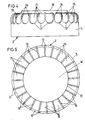
- a corresponding lattice structure also results with regard to the roof ventilation pipe, namely by proceeding in this regard in such a way that the pipe end has lattice openings extending into the pipe jacket wall, which are formed by vertical rungs, which emanate from an outermost circular rung and open into the jacket wall.
- the coherent, circumferential wall of the tube is thus converted into a large number of radially oriented wall sections. This leads to a favorable, directed air flow behavior (lamellae), whereby by a measure such that the grille openings are covered by the jacket wall of the cover cap, no driving rain or driving snow, leaves etc.
- the vertical rungs start below the upper edge of the outermost circular rungs.
- the corresponding plane offset leaves the lattice structure in an exposed position.
- the circular rungs are connected by three radial rungs. This purpose Radial rungs lying at the same angular distribution lead to an extremely stable lattice network.
- the support fingers are placed on the outermost ring rung and are arranged in a uniform angular distribution. The larger cross-sectional length of the support fingers is expediently in the radial direction, that is to say in a crossing relationship with the said circular ring rung.
- the roof ventilation pipe 1 passing through the roof formwork of a house is covered on the mouth side by a cover cap 2 (FIG. 7).
- the latter can be assigned by means of the supported plug-in locking connection. It can be a reversible type of connection.
- Push-fit locking and support are implemented at different points using different parts.
- the locking means are located in the center of the roof ventilation pipe 1, that is, in the longitudinal central axis x-x. It is a central, cylindrical projection 4. The latter is molded onto the cap 4. Its axial length is shorter than the jacket wall 5 of the cover cap 2.
- the latching anchoring of the projection 4 takes place in the center of a lattice structure G at the upper pipe end of the roof ventilation pipe 1, specifically in the interior of an inner circular rung 6. It is cylindrical in shape.
- the lower end wall 6 'of the inner circular ring 6 is gripped by the steep flank 7' of a locking lug 7.
- each of the four latching lugs 7 has a chamfer which promotes the plug-in / latching connection 7 ⁇ owns.
- the cross slit which can be clearly seen from FIG. 6, has an overall width running in the circumferential direction, which allows the locking lugs 7 to be bundled up to below the clear cross section of the inner circular ring rung 6.
- the steep flank 7 'of each locking lug 7 extends horizontally, that is, parallel to the plane of the end edge 6' of the circular rung.
- the cross slots are designated by 8. Their axial length, from the free end of the projection hend is dimensioned so that the slot bottom ends within the circular ring rung 6 (see. Fig. 6). In this way, a portion that can no longer be reduced in cross section is retained as a cylinder journal inside.
- the sleeve cavity extends to the level of the inner side 9 of the cover cap 2.
- the support means are decentralized. They consist of freely protruding support fingers 10 starting from the underside of the covering cap 2. A total of four such support fingers 10 are realized, with the same angular distribution. The spatial assignment in relation to the cross slots 8 is such that they are flush with them.
- the support fingers 10 are, seen in cross section, rectangular shape. The longer side of the rectangle runs approximately in the radial. As can be clearly seen in FIG. 7, the narrow sides of the support fingers converge in the direction of the lattice structure G.
- the support abutment here forms at least one outer annular ring 11.
- the latter extends concentrically to the inner circular ring 6.
- the annular peripheral end face 11 'of the circular ring 11 is crossed by the corresponding underside 10' of the supporting fingers 10. This underside is larger in area than the thickness of the circular ring rung 11 measured in this radial.
- the latter is of relatively low height and merges into a top surface 14 of the cover cap 2 via a cylindrical ring wall 13 which is concentrically aligned with the jacket wall 5 of the cover cap 2.
- the wall W forming the floor or the deck of the dome 12 can be made thinner, so that it creates a kind of flexible membrane. This allows the centrally located projection 4 even under axial tension by the steep flank 7 'of the locking lugs 7 ends slightly from the end face 6' in the basic position, so that by exerting a compressive force in the direction of arrow P with a corresponding axial displacement of the barb-like Projection 4 snaps behind the end face 6 '.
- the support fingers 10 arranged more in the edge region of the dome 12 are practically not included, i. H. relocatable.
- radially directed channels 15 extend from the dome 12, or respectively the outside of the ring wall 13, arranged on the upper side 14. These even run over the convexly rounded edge between top 14 and jacket wall 5 into the latter. Between the individual channels 15 there remain webs 16, which are connected by way of concave rounded channel sections 17. At the level of these channel sections 17, the casing wall 5 forms a projection 18 which can be seen in FIG. 6. The wall thickness is kept the same in both regions, except for the parts which have approximately twice the material accumulation due to the radial webs 16. The relevant area is extremely stable.
- the pipe end has lattice openings 18 extending into the pipe jacket wall.
- the latter are delimited by vertical rungs 19, which emanate from the outermost circular ring rung 11 and open into said jacket wall of the roof ventilation pipe 1. Accordingly, the connection of the lattice structure G is also extremely stable.
- the wall thickness of the ventilation pipe 1 corresponds to the thickness of the vertical rungs 19. While the transition region on the pipe side between the radially oriented vertical rungs 19 is rounded concavely, the inversely directed ends of the vertical rungs 19 go bluntly into the outer surface of the outermost one Annular rung 11 over.
- the convex curve has the reference number 20.
- the lattice openings 18 are overlapped like a bell edge by the jacket wall 5 of the cover cap 2 which extends concentrically in front of it.
- An overlapping assignment is expediently implemented (cf. FIG. 7).
- central circular ring rung 21 Between the innermost circular ring rung 6 and the outermost circular ring rung 11 there is also a central circular ring rung 21. This also runs concentrically with the rotationally symmetrically adjacent circular ring rungs 6, 11. These are connected to one another via radial rungs 22. A total of three such radial rungs are realized. The latter have the same angular spacing from one another and are in alignment with a vertical rung 19 which is attached to the outside and a total of 24 of which are provided.
- the lower end of the roof ventilation pipe 1 can have a screw thread following a flange, this for fastening with a final pipe part arranged in a joint (not shown in more detail).
Landscapes
- Engineering & Computer Science (AREA)
- Chemical & Material Sciences (AREA)
- Combustion & Propulsion (AREA)
- Mechanical Engineering (AREA)
- General Engineering & Computer Science (AREA)
- Ventilation (AREA)
- Tents Or Canopies (AREA)
Applications Claiming Priority (2)
| Application Number | Priority Date | Filing Date | Title |
|---|---|---|---|
| DE8806101U DE8806101U1 (de) | 1988-05-07 | 1988-05-07 | Dachentlüftungsrohr |
| DE8806101U | 1988-05-07 |
Publications (3)
| Publication Number | Publication Date |
|---|---|
| EP0341376A2 true EP0341376A2 (fr) | 1989-11-15 |
| EP0341376A3 EP0341376A3 (fr) | 1991-10-02 |
| EP0341376B1 EP0341376B1 (fr) | 1992-12-02 |
Family
ID=6823842
Family Applications (1)
| Application Number | Title | Priority Date | Filing Date |
|---|---|---|---|
| EP89102092A Expired - Lifetime EP0341376B1 (fr) | 1988-05-07 | 1989-02-08 | Tuyau d'aération de toit |
Country Status (3)
| Country | Link |
|---|---|
| US (1) | US4955167A (fr) |
| EP (1) | EP0341376B1 (fr) |
| DE (2) | DE8806101U1 (fr) |
Cited By (2)
| Publication number | Priority date | Publication date | Assignee | Title |
|---|---|---|---|---|
| WO1996004513A1 (fr) * | 1994-08-03 | 1996-02-15 | KLÖBER. Johannes | Tuyau d'aeration se montant sur un toit |
| EP3859219A1 (fr) * | 2020-02-03 | 2021-08-04 | WIRPLAST - Wiecek Spolka Jawna | Élément de positionnement |
Families Citing this family (15)
| Publication number | Priority date | Publication date | Assignee | Title |
|---|---|---|---|---|
| DE8813239U1 (de) * | 1988-10-21 | 1990-02-15 | Klöber, Johannes, 5828 Ennepetal | Dacheindeckungsplatte |
| US5369413A (en) * | 1993-07-02 | 1994-11-29 | Hazeltine Corp. | Q equalization in dual-element end-fire array antennas |
| US5876276A (en) * | 1997-09-12 | 1999-03-02 | Arbucci; Christopher B. | Collapsible chimney cap |
| US5897434A (en) * | 1997-10-24 | 1999-04-27 | Arbucci; Christopher B. | Chimney cap hood |
| GB2338057B (en) * | 1998-06-05 | 2002-08-28 | Ultraframe Uk Ltd | Improvements in glazed roofs |
| US6022269A (en) * | 1999-04-27 | 2000-02-08 | Christopher Arbucci | Stackable chimney cap |
| US6244006B1 (en) * | 1999-09-08 | 2001-06-12 | Richard Shue | Vent pipe cover protective device |
| USD486891S1 (en) | 2003-01-21 | 2004-02-17 | Richard W. Cronce, Jr. | Vent pipe protective cover |
| DE20313900U1 (de) * | 2003-09-04 | 2003-12-18 | Blau Kunststofftechnik Zweigniederlassung Der Tesma Europa Gmbh | Deckel, insbesondere Tankdeckel |
| DE102009043172A1 (de) * | 2009-09-26 | 2011-06-16 | Monier Roofing Components Gmbh | Dachdurchgangspfanne |
| USD642669S1 (en) | 2010-09-09 | 2011-08-02 | Jerry Cheek | Vent cap |
| US10663192B2 (en) | 2013-01-04 | 2020-05-26 | Fleming Vaughn Carroll | Vertical vent stack cap |
| US9416986B2 (en) | 2013-06-24 | 2016-08-16 | The Rectorseal Corporation | Valve for roof vent |
| US9534392B2 (en) * | 2014-02-24 | 2017-01-03 | Liberty Diversified International, Inc. | Telescoping pipe boot |
| US10024477B2 (en) * | 2016-06-08 | 2018-07-17 | Larry A. Villella | Anti-ice buildup system for roof vent pipes |
Family Cites Families (7)
| Publication number | Priority date | Publication date | Assignee | Title |
|---|---|---|---|---|
| US510884A (en) * | 1893-12-19 | Cap for sewer and other pipes | ||
| US1549813A (en) * | 1921-03-31 | 1925-08-18 | Gottlieb Burger Indermuhle | Head for chimneys, smoke pipes, and the like |
| US1490186A (en) * | 1922-01-06 | 1924-04-15 | Rowe Walter Eddie | Dustproof breather |
| US3892169A (en) * | 1974-02-26 | 1975-07-01 | Frank R Jarnot | Readily installed vent for flexible cover panel |
| AU5874980A (en) * | 1979-06-22 | 1981-01-08 | Gaf Corporation | Roof vent |
| US4399743A (en) * | 1981-10-15 | 1983-08-23 | Plastic Oddities, Inc. | Vent pipe cap |
| DE8710070U1 (de) * | 1987-07-23 | 1987-10-22 | Schnorr, Marin, 6729 Hatzenbühl | Überdach-Entlüftungsvorrichtung |
-
1988
- 1988-05-07 DE DE8806101U patent/DE8806101U1/de not_active Expired
-
1989
- 1989-02-08 EP EP89102092A patent/EP0341376B1/fr not_active Expired - Lifetime
- 1989-02-08 DE DE8989102092T patent/DE58902853D1/de not_active Expired - Fee Related
- 1989-04-14 US US07/338,875 patent/US4955167A/en not_active Expired - Fee Related
Cited By (2)
| Publication number | Priority date | Publication date | Assignee | Title |
|---|---|---|---|---|
| WO1996004513A1 (fr) * | 1994-08-03 | 1996-02-15 | KLÖBER. Johannes | Tuyau d'aeration se montant sur un toit |
| EP3859219A1 (fr) * | 2020-02-03 | 2021-08-04 | WIRPLAST - Wiecek Spolka Jawna | Élément de positionnement |
Also Published As
| Publication number | Publication date |
|---|---|
| DE8806101U1 (de) | 1989-09-07 |
| EP0341376B1 (fr) | 1992-12-02 |
| DE58902853D1 (de) | 1993-01-14 |
| EP0341376A3 (fr) | 1991-10-02 |
| US4955167A (en) | 1990-09-11 |
Similar Documents
| Publication | Publication Date | Title |
|---|---|---|
| EP0341376B1 (fr) | Tuyau d'aération de toit | |
| DE2520001C2 (de) | Raumteilersystem | |
| EP0991828B1 (fr) | Systeme de chevauchement | |
| DE69411379T2 (de) | Doppelboden mit modulbodenplatten | |
| DE8813239U1 (de) | Dacheindeckungsplatte | |
| DE3221128A1 (de) | Ringfoermiger fuellkoerper fuer gas-fluessigkeitskontakt | |
| EP1215448A2 (fr) | Tuyau de ventilation | |
| EP0018597A1 (fr) | Attache, notamment pour poser ou fixer des tuyaux de chauffage du sol sur le plancher | |
| DE3247506C2 (de) | Gasdichte Unterdecke | |
| DE4420807C2 (de) | Höhenverstellbares Stützelement | |
| AT396379B (de) | Dacheindeckung aus nebeneinanderliegend angeordneten blechtafeln | |
| DE3607428A1 (de) | Traggeruest fuer haengedecke | |
| EP0537727B1 (fr) | Dispositif d'assemblage pour panneaux et/ou armatures en fer d'un coffrage composite | |
| DE3317291C1 (de) | Firstziegel für eine Firstentlüftung | |
| EP0211231A1 (fr) | Cabine pour bains de vapeur | |
| WO1997001008A1 (fr) | Dispositif permettant de fixer des armatures | |
| CH443432A (de) | Mehrfacher Verdrahtungskanal | |
| DE29609688U1 (de) | Fugenband mit Injektionskanal | |
| DE3116154C2 (fr) | ||
| CH632040A5 (en) | Ventilating device for roofs | |
| DE8705506U1 (de) | Zum Einsetzen in eine Schalung für ein Betonbauteil dienende Vorrichtung | |
| EP0423382B1 (fr) | Assemblage de combustible nucléaire | |
| DE3509941A1 (de) | Schneehaltedachziegel | |
| DE2303057C3 (de) | Eckverbinder mit Anordnungsmöglichkeiten in verschiedenen Winkelstellungen | |
| DE7833804U1 (de) | Hoehenverstellbarer moebelfuss |
Legal Events
| Date | Code | Title | Description |
|---|---|---|---|
| PUAI | Public reference made under article 153(3) epc to a published international application that has entered the european phase |
Free format text: ORIGINAL CODE: 0009012 |
|
| AK | Designated contracting states |
Kind code of ref document: A2 Designated state(s): BE DE FR GB NL |
|
| PUAL | Search report despatched |
Free format text: ORIGINAL CODE: 0009013 |
|
| AK | Designated contracting states |
Kind code of ref document: A3 Designated state(s): BE DE FR GB NL |
|
| 17P | Request for examination filed |
Effective date: 19910911 |
|
| 17Q | First examination report despatched |
Effective date: 19920323 |
|
| GRAA | (expected) grant |
Free format text: ORIGINAL CODE: 0009210 |
|
| AK | Designated contracting states |
Kind code of ref document: B1 Designated state(s): BE DE FR GB NL |
|
| ET | Fr: translation filed | ||
| REF | Corresponds to: |
Ref document number: 58902853 Country of ref document: DE Date of ref document: 19930114 |
|
| GBT | Gb: translation of ep patent filed (gb section 77(6)(a)/1977) |
Effective date: 19930203 |
|
| PLBE | No opposition filed within time limit |
Free format text: ORIGINAL CODE: 0009261 |
|
| STAA | Information on the status of an ep patent application or granted ep patent |
Free format text: STATUS: NO OPPOSITION FILED WITHIN TIME LIMIT |
|
| 26N | No opposition filed | ||
| PGFP | Annual fee paid to national office [announced via postgrant information from national office to epo] |
Ref country code: GB Payment date: 19990111 Year of fee payment: 11 |
|
| PGFP | Annual fee paid to national office [announced via postgrant information from national office to epo] |
Ref country code: FR Payment date: 19990119 Year of fee payment: 11 |
|
| PGFP | Annual fee paid to national office [announced via postgrant information from national office to epo] |
Ref country code: NL Payment date: 19990120 Year of fee payment: 11 |
|
| PGFP | Annual fee paid to national office [announced via postgrant information from national office to epo] |
Ref country code: BE Payment date: 19990121 Year of fee payment: 11 |
|
| PG25 | Lapsed in a contracting state [announced via postgrant information from national office to epo] |
Ref country code: GB Free format text: LAPSE BECAUSE OF NON-PAYMENT OF DUE FEES Effective date: 20000208 |
|
| PG25 | Lapsed in a contracting state [announced via postgrant information from national office to epo] |
Ref country code: BE Free format text: LAPSE BECAUSE OF NON-PAYMENT OF DUE FEES Effective date: 20000228 |
|
| BERE | Be: lapsed |
Owner name: HANS KLOBER K.G. Effective date: 20000228 |
|
| PG25 | Lapsed in a contracting state [announced via postgrant information from national office to epo] |
Ref country code: NL Free format text: LAPSE BECAUSE OF NON-PAYMENT OF DUE FEES Effective date: 20000901 |
|
| GBPC | Gb: european patent ceased through non-payment of renewal fee |
Effective date: 20000208 |
|
| PG25 | Lapsed in a contracting state [announced via postgrant information from national office to epo] |
Ref country code: FR Free format text: LAPSE BECAUSE OF NON-PAYMENT OF DUE FEES Effective date: 20001031 |
|
| NLV4 | Nl: lapsed or anulled due to non-payment of the annual fee |
Effective date: 20000901 |
|
| REG | Reference to a national code |
Ref country code: FR Ref legal event code: ST |
|
| PGFP | Annual fee paid to national office [announced via postgrant information from national office to epo] |
Ref country code: DE Payment date: 20001229 Year of fee payment: 13 |
|
| PG25 | Lapsed in a contracting state [announced via postgrant information from national office to epo] |
Ref country code: DE Free format text: LAPSE BECAUSE OF NON-PAYMENT OF DUE FEES Effective date: 20020903 |