EP0341177B1 - Regelungsmodul für eine Rohrheizung - Google Patents
Regelungsmodul für eine Rohrheizung Download PDFInfo
- Publication number
- EP0341177B1 EP0341177B1 EP89440040A EP89440040A EP0341177B1 EP 0341177 B1 EP0341177 B1 EP 0341177B1 EP 89440040 A EP89440040 A EP 89440040A EP 89440040 A EP89440040 A EP 89440040A EP 0341177 B1 EP0341177 B1 EP 0341177B1
- Authority
- EP
- European Patent Office
- Prior art keywords
- relay
- plotter
- thermostat
- board
- indicators
- Prior art date
- Legal status (The legal status is an assumption and is not a legal conclusion. Google has not performed a legal analysis and makes no representation as to the accuracy of the status listed.)
- Expired - Lifetime
Links
Images

Classifications
-
- H—ELECTRICITY
- H05—ELECTRIC TECHNIQUES NOT OTHERWISE PROVIDED FOR
- H05B—ELECTRIC HEATING; ELECTRIC LIGHT SOURCES NOT OTHERWISE PROVIDED FOR; CIRCUIT ARRANGEMENTS FOR ELECTRIC LIGHT SOURCES, IN GENERAL
- H05B3/00—Ohmic-resistance heating
- H05B3/40—Heating elements having the shape of rods or tubes
- H05B3/54—Heating elements having the shape of rods or tubes flexible
- H05B3/56—Heating cables
-
- G—PHYSICS
- G05—CONTROLLING; REGULATING
- G05D—SYSTEMS FOR CONTROLLING OR REGULATING NON-ELECTRIC VARIABLES
- G05D23/00—Control of temperature
- G05D23/19—Control of temperature characterised by the use of electric means
- G05D23/275—Control of temperature characterised by the use of electric means with sensing element expanding, contracting, or fusing in response to changes of temperature
-
- H—ELECTRICITY
- H05—ELECTRIC TECHNIQUES NOT OTHERWISE PROVIDED FOR
- H05K—PRINTED CIRCUITS; CASINGS OR CONSTRUCTIONAL DETAILS OF ELECTRIC APPARATUS; MANUFACTURE OF ASSEMBLAGES OF ELECTRICAL COMPONENTS
- H05K1/00—Printed circuits
- H05K1/18—Printed circuits structurally associated with non-printed electric components
Definitions
- the present invention relates to the field of electrical tracing of pipes or tanks and relates to a regulation module or electric tracer.
- Electrical tracing consists in providing a pipe or a tank, transporting or enclosing materials to be maintained at a given temperature or within a given temperature range, with a flat ribbon of thin thickness constituted by copper conductors in which generally a 220 volt current, these conductors being separated by a semiconductor material producing a release of heat, the assembly being covered with at least one insulation sheath.
- the tracers are placed linearly or in a spiral on pipes, tanks, hoppers, valves or other materials to be traced.
- the heating power per linear meter varies. This power is generally determined by the suppliers of the tracer tapes, taking into account the ambient temperature, the nature of the container, the length of tape to be laid, the insulation and the desired temperature.
- frost protection There are two types of heat tracing facilities, namely frost protection and temperature maintenance.
- the frost-proofing installations generally include a room or control thermostat placed in an unfavorable location, which activates the tracer when a predetermined temperature is reached. Such an installation is used in particular for the protection of water pipes.
- Heat tracing facilities are used to maintain certain materials at a predetermined temperature. As For example, considering a product crystallizing at 30 ° C, its temperature should be maintained at around 40 ° C in order to avoid possible obstruction of pipes.
- two thermostats are generally used, one of which turns the tracer ribbon on and off and which is adjusted to the temperature and the other of which, which is adjusted to a temperature between the crystallization temperature and the temperature of hold, triggers an audible or visual alarm in the event of a faulty operation of the first thermostat.
- the control of the tracing installations is carried out by means of an electrical assembly comprising a power part and a regulation part.
- the power section is made up of a two-pole protective circuit breaker, a differential safety circuit breaker, a start-up contactor, a contactor start-up timer and two fuse holders for protecting the control and signage
- the regulation part generally includes relays for putting the plotter on and / or off and the audible and / or visual alarm. These relays are mounted on a bar by means of fixing accessories and are connected by means of wires fitted with end caps to numbered connection rings, as well as to indicator lights for operation mounted on a cabinet door. control together with buttons and switches.
- the realization of the regulation part requires a relatively long assembly time due to the various tracings, drillings and connections to be made.
- the object of the present invention is to overcome the drawbacks of the regulating part of known tracing installations.
- a regulation module for electric plotter characterized in that it is essentially constituted by a plate, forming a printed circuit board, on which are mounted a low thermostat relay recording alarm information from a minimum operating temperature detection thermostat, a high thermostat relay for switching a ribbon on or off, a relay of a tracer fault activated in the event of detection of a discontinuity or a fault in the insulation of the tracer tape, a general fault relay grouping together information from the low thermostat relays and / or tracer fault, a relay plotter continuity controlling the continuity of the plotter conductors, an auxiliary contactor relay operating simultaneously with the high thermostat relay, as well as a switch with three fixed positions, namely stop, automatic operation controlled by the temperature regulation thermostat installation and manual operation corresponding to forced operation, by a set of signaling operating states of org control handles provided with indicator lights arranged on a front panel extending perpendicular to the plate constituting the printed circuit and connected to the latter and by a plug-in connector for the plate constituting the printed circuit.
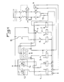
- the regulation module for electric plotter essentially consists of a plate 1, forming a printed circuit, on which are mounted a low thermostat relay 2, a high thermostat relay 3, a tracer fault relay 4, a general fault relay 5, a tracer continuity relay 6, an auxiliary contactor relay 7, as well as a switch 8 with three fixed positions, by an assembly 9 for signaling the operating states of the control members provided with indicator lights arranged on a front face plate 10 extending perpendicularly to the plate 1 constituting the printed circuit. and connected to the latter and by a connector 11 for plugging in the plate 1 constituting the printed circuit.
- the low thermostat relay 2 is intended for recording alarm information delivered by a thermostat 12 for detecting the minimum operating temperature, that is to say the minimum temperature to be delivered by the tracer for maintain the line, the tank, or others, so equipped at a frost-free temperature or at a minimum temperature of use.
- the high thermostat relay 3 is used to activate or deactivate the tracer tape 13 after energizing by means of the regulation thermostat 14.
- the closed position of relay 3 corresponds to normal operation.
- the tracer fault relay 4 is actuated when the tracer tape 13 has a discontinuity or an insulation fault and cuts off the power to the power contactor 15.
- the general fault relay 5 groups together the information which comes from the low thermostat 2 and / or tracer fault 4 relays. This relay allows, for example, to send back to a control room the malfunction signal of the tracer 13 by simple connection of an electric line to the corresponding connection pin of connector 11.
- the plotter continuity relay 6 checks the continuity of the plotter conductors 13. This check is carried out by applying two phases at 220 volts at one end of said conductors and by checking the voltage at the other end of these phases. This relay 6 is, in normal operation, activated as soon as the module is put into service.
- the auxiliary contactor relay 7 operates simultaneously with the high thermostat relay 3 and one of its contacts actuates the power contactor 15.
- the switch 8 is a switch with three fixed positions allowing, in the central position, stopping the operation, in an automatic position the operation controlled by the regulating thermostat 14 and in a manual position a forced operation decided by the user.
- the module according to the invention is advantageously placed in an electrical cabinet in the manner of a plug-in drawer, the cabinet door being advantageously equipped with a window and possibly with a switch connected to switch 8 for carrying out an external command.
- the assembly 9 for signaling the operating states of the control members consists, on the one hand, of indicators 16 to 21 in the form of light-emitting diodes arranged on the front panel 10 signaling the state of the relays 2 to 7 and, on the other hand, by indicators 22 to 25, respectively for signaling the operation of the tracer tape 13, reaching the predetermined temperature by adjusting the regulating thermostat 14, reaching the alarm temperature and signaling of a discontinuity of the tracer ribbon 13 or of a triggering of the power part, these indicators 16 to 25 being connected to the corresponding circuits and members via capacitors 26 to 36 and resistors 38 to 48, as well as diodes 50 to 71, the operating state of the indicators being checked by means of a test button 37 which may possibly be doubled by a second button arranged on the door of the cabinet.
- the LEDs 16 to 21 which indicate the operating status of the relays 2 to 7 are only intended to signal a faulty circuit in order to allow rapid troubleshooting.
- the capacitors 27 to 36 are inserted into the supply circuit of the tracer tape 13, together with the resistors 38 to 47, in order to allow direct supply of the diodes 6 to 25 and the capacitor 26 and the resistor 48, which respectively have a capacity equal to that of the total of the capacitors 27 to 36 and a resistor inversely proportional to that of the resistors 38 to 47, are also inserted in the supply circuit of the tracer tape 13 in order to allow the supply of the indicators 16 to 25 simultaneously of the lamp test using button 37.
- the diodes 50 to 59 are only used for the lamp test circuit and allow this test by means of the single button 37. In addition, these diodes prohibit a return of current during normal operation.
- the diode 60 and the diodes 62 to 71 are intended to authorize the discharge of the capacitor 26 during the second half-wave of the current.
- the connector 11 allows the inputs and outputs of all the information of the module according to the invention, for example from and towards a control room.
- this module is very compact and allows a significant saving of space compared to the existing control circuits and the labor cost for installing this module is very significantly reduced compared to said existing circuits.
Landscapes
- Physics & Mathematics (AREA)
- General Physics & Mathematics (AREA)
- Engineering & Computer Science (AREA)
- Automation & Control Theory (AREA)
- Pipe Accessories (AREA)
- Resistance Heating (AREA)
- Devices That Are Associated With Refrigeration Equipment (AREA)
- Control Of Resistance Heating (AREA)
- Electronic Switches (AREA)
- Cold Air Circulating Systems And Constructional Details In Refrigerators (AREA)
- Testing Electric Properties And Detecting Electric Faults (AREA)
Claims (4)
- Regelungsmodul für eine elektrische Begleitheizung, mit einer eine gedruckte Schaltung bildenden Platine (1), auf welcher angeordnet sind: ein einem unteren Temperaturgrenzwert zugeordnetes Thermostatrelais (2), welches eine Alarminformation registriert, die von einem Thermostaten (12) abgegeben wird, der auf das Vorliegen einer minimalen Arbeitstemperatur anspricht, ein einem oberen Temperaturgrenzwert zugeordnetes Thermostatrelais (3), durch welches ein Begleitheizband (13) ein- und ausgeschaltet wird, und ein Heizband-Fehlerrelais (4), das betätigt wird, wenn eine Unterbrechung des Begleitheizbandes (13) oder ein Fehler in der Isolierung des Begleitheizbandes (13) vorliegt, dadurch gekennzeichnet, daß die Platine (1) zusätzlich aufweist: ein globales Fehlerrelais (5), welches die Informationen zusammenfaßt, welche von dem dem unteren Temperaturgrenzwert zugeordneten Thermostatrelais (2) und/oder dem Heizband-Fehlerrelais (4) bereitgestellt werden; ein Heizband-Durchgangsrelais (6), welches den Durchgang der Leiter des Begleitheizbandes überwacht; ein Hilfskontaktrelais (7), welches gleichzeitig mit dem dem oberen Temperaturgrenzwert zugeordneten Relais (3) arbeitet; einen Schalter (8) mit drei Arbeitsstellungen, nämlich einer Arbeitsstellung "Halt", einer Arbeitsstellung "Automatischer Betrieb", in welcher eine Steuerung durch den Regelthermostat (14) der Anlage erfolgt, und eine Arbeitsstellung "manueller Betrieb", in welcher ein Arbeiten zwangsweise herbeigeführt wird; und eine Meldeeinheit (9), welche die Betriebszustände der Steuermittel meldet und mit Sichtanzeigen versehen ist, die auf einer vorderen Stirnplatte (10) angeordnet sind, welche sich in zur die gedruckte Schaltung bildenden Platine (1) senkrechter Richtung erstreckt und mit dieser durch einen Steckverbinder (11) der die gedruckte Schaltung bildenden Platine (1) verbunden ist.
- Regelungsmodul nach Anspruch 1, dadurch gekennzeichnet, daß er vorzugsweise in einem Steuerschrank nach Art eines steckbaren Einschubes angeordnet ist, wobei die Tür des Schrankes vorzugsweise mit einem Fenster ausgebildet ist und gegebenenfalls mit einem Schalter versehen ist, der mit dem drei Arbeitsstellungen aufweisenden Schalter (8) verbunden ist, um eine externe Betätigung zu ermöglichen.
- Regelungsmodul nach Anspruch 1, dadurch gekennzeichnet, daß die Meldeeinheit (9), welche die Betriebszustände der Steuermittel meldet, einerseits Sichtanzeigen (16 bis 21) für den Betriebszustand der Relais (2 bis 7) in Form von lichtemittierenden Dioden aufweist, die auf der vorderen Stirnplatte (10) angeordnet sind, und andererseits Sichtanzeigen (22 bis 25) umfaßt, welche das Arbeiten des Begleitheizbandes (13), das Erreichen der durch Einstellung des Regelthermostaten (14) vorgegebenen Temperatur, das Erreichen der Alarmtemperatur und das Vorliegen einer Unterbrechung des Begleitheizbandes (13) oder ein Auslösen des Leistungsteiles signalisieren, wobei die Sichtanzeigen (16 bis 25) mit entsprechenden Schaltkreisen und entsprechenden Organen über Kondensatoren (26 bis 36) und Widerstände (38 bis 48) sowie Dioden (50 bis 71) verbunden sind, und wobei das Arbeiten der Sichtanzeigen unter Verwendung eines Testknopfes (37) überprüft wird, der gegebenenfalls durch einen zweiten Knopf verdoppelt sein kann, der auf der Schranktür angeordnet ist.
- Regelungsmodul nach Anspruch 1, dadurch gekennzeichnet, daß die Kondensatoren (27 bis 36) in den Speisekreis des Begleitheizbandes (13) zusammen mit den Widerständen (38 bis 47) eingefügt sind, damit man eine direkte Versorgung der Dioden (16 bis 25) sowie des Kondensators (26) und des Widerstandes (48) erhält wobei die letztgenannten Bauelemente eine Kapazität haben, die gleich der Gesamtkapazität der Kondensatoren (27 bis 36) ist, bzw. einen Widerstand haben, der umgekehrt porportional zum Gesamtwiderstand der Widerstände (38 bis 47) ist, wobei diese Teile gleichermaßen in den Speisekreis des Begleitheizbandes (13) eingefügt sind, damit man gleichzeitig mit der Lampenprüfung mittels des Knopfes (37) eine Speisung der Sichtanzeigen (16 bis 25) erhält.
Priority Applications (1)
| Application Number | Priority Date | Filing Date | Title |
|---|---|---|---|
| AT89440040T ATE95327T1 (de) | 1988-05-05 | 1989-05-03 | Regelungsmodul fuer eine rohrheizung. |
Applications Claiming Priority (2)
| Application Number | Priority Date | Filing Date | Title |
|---|---|---|---|
| FR8806255A FR2631197B1 (fr) | 1988-05-05 | 1988-05-05 | Module de regulation pour traceur electrique |
| FR8806255 | 1988-05-05 |
Publications (2)
| Publication Number | Publication Date |
|---|---|
| EP0341177A1 EP0341177A1 (de) | 1989-11-08 |
| EP0341177B1 true EP0341177B1 (de) | 1993-09-29 |
Family
ID=9366148
Family Applications (1)
| Application Number | Title | Priority Date | Filing Date |
|---|---|---|---|
| EP89440040A Expired - Lifetime EP0341177B1 (de) | 1988-05-05 | 1989-05-03 | Regelungsmodul für eine Rohrheizung |
Country Status (5)
| Country | Link |
|---|---|
| EP (1) | EP0341177B1 (de) |
| AT (1) | ATE95327T1 (de) |
| DE (1) | DE68909486T2 (de) |
| ES (1) | ES2046519T3 (de) |
| FR (1) | FR2631197B1 (de) |
Cited By (1)
| Publication number | Priority date | Publication date | Assignee | Title |
|---|---|---|---|---|
| CN105133796A (zh) * | 2015-08-24 | 2015-12-09 | 中国铁道科学研究院铁道建筑研究所 | 电伴热面板及自动融冰化雪系统 |
Families Citing this family (1)
| Publication number | Priority date | Publication date | Assignee | Title |
|---|---|---|---|---|
| CN117596726B (zh) * | 2023-12-22 | 2024-05-10 | 山东绿光热控科技有限公司 | 一种电伴热带的自适应运行控制方法 |
Family Cites Families (3)
| Publication number | Priority date | Publication date | Assignee | Title |
|---|---|---|---|---|
| AU552081B2 (en) * | 1980-06-25 | 1986-05-22 | Rheem Australia Pty Limited | Thermal control unit |
| US4453159A (en) * | 1981-09-28 | 1984-06-05 | Thermon Manufacturing Company | Self-monitoring heat tracing system |
| US4575617A (en) * | 1984-04-12 | 1986-03-11 | Cooperheat | Heat tracing tape and power control system |
-
1988
- 1988-05-05 FR FR8806255A patent/FR2631197B1/fr not_active Expired - Lifetime
-
1989
- 1989-05-03 ES ES198989440040T patent/ES2046519T3/es not_active Expired - Lifetime
- 1989-05-03 EP EP89440040A patent/EP0341177B1/de not_active Expired - Lifetime
- 1989-05-03 DE DE89440040T patent/DE68909486T2/de not_active Expired - Fee Related
- 1989-05-03 AT AT89440040T patent/ATE95327T1/de not_active IP Right Cessation
Cited By (1)
| Publication number | Priority date | Publication date | Assignee | Title |
|---|---|---|---|---|
| CN105133796A (zh) * | 2015-08-24 | 2015-12-09 | 中国铁道科学研究院铁道建筑研究所 | 电伴热面板及自动融冰化雪系统 |
Also Published As
| Publication number | Publication date |
|---|---|
| EP0341177A1 (de) | 1989-11-08 |
| DE68909486D1 (de) | 1993-11-04 |
| FR2631197B1 (fr) | 1991-03-15 |
| FR2631197A1 (fr) | 1989-11-10 |
| DE68909486T2 (de) | 1994-05-11 |
| ATE95327T1 (de) | 1993-10-15 |
| ES2046519T3 (es) | 1994-02-01 |
Similar Documents
| Publication | Publication Date | Title |
|---|---|---|
| EP0708498B1 (de) | Steckdoseneinheit und Verlängerungsschnur | |
| US5334973A (en) | Leak detection and shut-off apparatus | |
| FI80816C (fi) | Datastyrd kopplingsanordning. | |
| FR2621988A1 (fr) | Appareil diagnostique pour une unite de chauffage de l'eau | |
| EP0341177A1 (de) | Regelungsmodul für eine Rohrheizung | |
| EP3709333B1 (de) | Elektrisches gerät zur versorgung oder nichtversorgung einer last in abhängigkeit vom ein- oder aus-zustand eines bedienorgans | |
| FR2497013A1 (fr) | Dispositif de delestage d'une installation electrique basse tension | |
| EP0266254A1 (de) | Einrichtung zur Überwachung von elektrischen Motoren | |
| US2479621A (en) | Magnetically operated switch | |
| GB2310751A (en) | Safety system with a gas supply cut-off valve | |
| US1148411A (en) | Electric alarm. | |
| FR2517440A1 (fr) | Disjoncteur de courant en cas de detection d'une fuite d'eau | |
| FR2601453A1 (fr) | Detecteur de gaz applicable a un support a encastrement | |
| EP0253709A1 (de) | Überwachungsanlage mit in einer Schleife gespeisten Detektoren | |
| FR2656105A1 (fr) | Dispositif de controle de fonctionnement de charges electriques d'un vehicule. | |
| EP0161967A1 (de) | KÜhlschrank mit zwei Fächern | |
| EP0127533B1 (de) | Sicherungen von elektrischen Installationen | |
| FR2480346A1 (fr) | Dispositif d'ouverture et/ou de fermeture d'un volet d'aeration | |
| KR0143741B1 (ko) | 엔진 발전기의 시퀀스 경보 회로 | |
| FR2835108A1 (fr) | Dispositif de controle de fonctionnement d'un onduleur | |
| FR2570505A1 (fr) | Circuit a boucle de courant transmetteur d'informations | |
| JP3038411B2 (ja) | 地区ベル鳴動システム | |
| NL1002229C2 (nl) | Inrichting voor het leveren van een stroom van leidingwater, in het bijzonder in een oog- of veiligheidsdouche. | |
| GB2025136A (en) | Fire sensing trip device | |
| FR2504482A1 (fr) | Dispositif de securite de lignes pour appareils de transport par cable |
Legal Events
| Date | Code | Title | Description |
|---|---|---|---|
| PUAI | Public reference made under article 153(3) epc to a published international application that has entered the european phase |
Free format text: ORIGINAL CODE: 0009012 |
|
| AK | Designated contracting states |
Kind code of ref document: A1 Designated state(s): AT BE CH DE ES FR GB GR IT LI LU NL SE |
|
| 17P | Request for examination filed |
Effective date: 19900426 |
|
| 17Q | First examination report despatched |
Effective date: 19921221 |
|
| GRAA | (expected) grant |
Free format text: ORIGINAL CODE: 0009210 |
|
| AK | Designated contracting states |
Kind code of ref document: B1 Designated state(s): AT BE CH DE ES FR GB GR IT LI LU NL SE |
|
| PG25 | Lapsed in a contracting state [announced via postgrant information from national office to epo] |
Ref country code: IT Free format text: LAPSE BECAUSE OF FAILURE TO SUBMIT A TRANSLATION OF THE DESCRIPTION OR TO PAY THE FEE WITHIN THE PRE;WARNING: LAPSES OF ITALIAN PATENTS WITH EFFECTIVE DATE BEFORE 2007 MAY HAVE OCCURRED AT ANY TIME BEFORE 2007. THE CORRECT EFFECTIVE DATE MAY BE DIFFERENT FROM THE ONE RECORDED.SCRIBED TIME-LIMIT Effective date: 19930929 Ref country code: GR Free format text: LAPSE BECAUSE OF FAILURE TO SUBMIT A TRANSLATION OF THE DESCRIPTION OR TO PAY THE FEE WITHIN THE PRESCRIBED TIME-LIMIT Effective date: 19930929 Ref country code: AT Effective date: 19930929 Ref country code: SE Effective date: 19930929 |
|
| REF | Corresponds to: |
Ref document number: 95327 Country of ref document: AT Date of ref document: 19931015 Kind code of ref document: T |
|
| REF | Corresponds to: |
Ref document number: 68909486 Country of ref document: DE Date of ref document: 19931104 |
|
| REG | Reference to a national code |
Ref country code: ES Ref legal event code: FG2A Ref document number: 2046519 Country of ref document: ES Kind code of ref document: T3 |
|
| GBT | Gb: translation of ep patent filed (gb section 77(6)(a)/1977) |
Effective date: 19940113 |
|
| PG25 | Lapsed in a contracting state [announced via postgrant information from national office to epo] |
Ref country code: LU Free format text: LAPSE BECAUSE OF NON-PAYMENT OF DUE FEES Effective date: 19940531 |
|
| PLBE | No opposition filed within time limit |
Free format text: ORIGINAL CODE: 0009261 |
|
| STAA | Information on the status of an ep patent application or granted ep patent |
Free format text: STATUS: NO OPPOSITION FILED WITHIN TIME LIMIT |
|
| 26N | No opposition filed | ||
| PGFP | Annual fee paid to national office [announced via postgrant information from national office to epo] |
Ref country code: GB Payment date: 19950421 Year of fee payment: 7 |
|
| PGFP | Annual fee paid to national office [announced via postgrant information from national office to epo] |
Ref country code: BE Payment date: 19950426 Year of fee payment: 7 |
|
| PGFP | Annual fee paid to national office [announced via postgrant information from national office to epo] |
Ref country code: ES Payment date: 19950510 Year of fee payment: 7 |
|
| PGFP | Annual fee paid to national office [announced via postgrant information from national office to epo] |
Ref country code: DE Payment date: 19950520 Year of fee payment: 7 |
|
| PGFP | Annual fee paid to national office [announced via postgrant information from national office to epo] |
Ref country code: NL Payment date: 19950531 Year of fee payment: 7 |
|
| PGFP | Annual fee paid to national office [announced via postgrant information from national office to epo] |
Ref country code: CH Payment date: 19950822 Year of fee payment: 7 |
|
| PG25 | Lapsed in a contracting state [announced via postgrant information from national office to epo] |
Ref country code: GB Effective date: 19960503 |
|
| PG25 | Lapsed in a contracting state [announced via postgrant information from national office to epo] |
Ref country code: ES Free format text: LAPSE BECAUSE OF NON-PAYMENT OF DUE FEES Effective date: 19960504 |
|
| PG25 | Lapsed in a contracting state [announced via postgrant information from national office to epo] |
Ref country code: CH Effective date: 19960531 Ref country code: BE Effective date: 19960531 Ref country code: LI Effective date: 19960531 |
|
| BERE | Be: lapsed |
Owner name: BELANGER BERNARD Effective date: 19960531 |
|
| PG25 | Lapsed in a contracting state [announced via postgrant information from national office to epo] |
Ref country code: NL Effective date: 19961201 |
|
| GBPC | Gb: european patent ceased through non-payment of renewal fee |
Effective date: 19960503 |
|
| REG | Reference to a national code |
Ref country code: CH Ref legal event code: PL |
|
| PG25 | Lapsed in a contracting state [announced via postgrant information from national office to epo] |
Ref country code: DE Effective date: 19970201 |
|
| NLV4 | Nl: lapsed or anulled due to non-payment of the annual fee |
Effective date: 19961201 |
|
| REG | Reference to a national code |
Ref country code: ES Ref legal event code: FD2A Effective date: 19990405 |
|
| PGFP | Annual fee paid to national office [announced via postgrant information from national office to epo] |
Ref country code: FR Payment date: 20020521 Year of fee payment: 14 |
|
| PG25 | Lapsed in a contracting state [announced via postgrant information from national office to epo] |
Ref country code: FR Free format text: LAPSE BECAUSE OF NON-PAYMENT OF DUE FEES Effective date: 20040130 |
|
| REG | Reference to a national code |
Ref country code: FR Ref legal event code: ST |