EP3709333B1 - Elektrisches gerät zur versorgung oder nichtversorgung einer last in abhängigkeit vom ein- oder aus-zustand eines bedienorgans - Google Patents
Elektrisches gerät zur versorgung oder nichtversorgung einer last in abhängigkeit vom ein- oder aus-zustand eines bedienorgans Download PDFInfo
- Publication number
- EP3709333B1 EP3709333B1 EP20162897.1A EP20162897A EP3709333B1 EP 3709333 B1 EP3709333 B1 EP 3709333B1 EP 20162897 A EP20162897 A EP 20162897A EP 3709333 B1 EP3709333 B1 EP 3709333B1
- Authority
- EP
- European Patent Office
- Prior art keywords
- terminal
- command
- state
- load
- circuit breaker
- Prior art date
- Legal status (The legal status is an assumption and is not a legal conclusion. Google has not performed a legal analysis and makes no representation as to the accuracy of the status listed.)
- Active
Links
Images


Classifications
-
- H—ELECTRICITY
- H01—ELECTRIC ELEMENTS
- H01H—ELECTRIC SWITCHES; RELAYS; SELECTORS; EMERGENCY PROTECTIVE DEVICES
- H01H47/00—Circuit arrangements not adapted to a particular application of the relay and designed to obtain desired operating characteristics or to provide energising current
-
- H—ELECTRICITY
- H01—ELECTRIC ELEMENTS
- H01H—ELECTRIC SWITCHES; RELAYS; SELECTORS; EMERGENCY PROTECTIVE DEVICES
- H01H47/00—Circuit arrangements not adapted to a particular application of the relay and designed to obtain desired operating characteristics or to provide energising current
- H01H47/22—Circuit arrangements not adapted to a particular application of the relay and designed to obtain desired operating characteristics or to provide energising current for supplying energising current for relay coil
- H01H47/223—Circuit arrangements not adapted to a particular application of the relay and designed to obtain desired operating characteristics or to provide energising current for supplying energising current for relay coil adapted to be supplied by AC
-
- H—ELECTRICITY
- H01—ELECTRIC ELEMENTS
- H01H—ELECTRIC SWITCHES; RELAYS; SELECTORS; EMERGENCY PROTECTIVE DEVICES
- H01H50/00—Details of electromagnetic relays
- H01H50/64—Driving arrangements between movable part of magnetic circuit and contact
-
- H—ELECTRICITY
- H01—ELECTRIC ELEMENTS
- H01H—ELECTRIC SWITCHES; RELAYS; SELECTORS; EMERGENCY PROTECTIVE DEVICES
- H01H9/00—Details of switching devices, not covered by groups H01H1/00 - H01H7/00
- H01H9/54—Circuit arrangements not adapted to a particular application of the switching device and for which no provision exists elsewhere
-
- H—ELECTRICITY
- H01—ELECTRIC ELEMENTS
- H01H—ELECTRIC SWITCHES; RELAYS; SELECTORS; EMERGENCY PROTECTIVE DEVICES
- H01H47/00—Circuit arrangements not adapted to a particular application of the relay and designed to obtain desired operating characteristics or to provide energising current
- H01H47/001—Functional circuits, e.g. logic, sequencing, interlocking circuits
-
- H—ELECTRICITY
- H01—ELECTRIC ELEMENTS
- H01H—ELECTRIC SWITCHES; RELAYS; SELECTORS; EMERGENCY PROTECTIVE DEVICES
- H01H50/00—Details of electromagnetic relays
- H01H50/02—Bases; Casings; Covers
- H01H50/021—Bases; Casings; Covers structurally combining a relay and an electronic component, e.g. varistor, RC circuit
-
- H—ELECTRICITY
- H01—ELECTRIC ELEMENTS
- H01H—ELECTRIC SWITCHES; RELAYS; SELECTORS; EMERGENCY PROTECTIVE DEVICES
- H01H50/00—Details of electromagnetic relays
- H01H50/02—Bases; Casings; Covers
- H01H50/04—Mounting complete relay or separate parts of relay on a base or inside a case
- H01H50/047—Details concerning mounting a relays
Definitions
- the invention relates to an electrical device to be connected by cables to an alternating current source, to a load and to a control member, in order to leave, or not, said current source to supply said load according to on or off states. taken by the control unit.
- Contactor 100 shown on figure 1 is in the modular format, that is to say it has a generally parallelepipedal shape with two main faces, respectively a left face 101 and a right face 102, and side faces extending from one to the other. another of the main faces 101 and 102, namely a rear face 103, an upper face 104, a front face 105 and a lower face 106, the rear face 103 having a notch 107 for mounting the contactor 100 on a support rail such as than 112 standardized with ⁇ profile, in particular visible on the figure 3 , a protective enclosure such as a cabinet, box or electrical box.
- the width of the contactor 100 which corresponds to the distance between the left face 101 and the right face 102, is a multiple of a standardized value, known as " modulus ", which is order of 18 mm.
- Contactor 100 is one module wide.
- the front face 105 has, in a central position, a nose 108 having a key 109, which can selectively take one of three positions, respectively an automatic operating position, a forced operating position and a stop position.
- the contactor 100 In the automatic operating position, the contactor 100 allows or not the supply of a load depending respectively on whether a control member is on or blocked. In the forced operating position, the contactor 100 permanently enables the load to be supplied. In the off position, the contactor 100 permanently prevents power to the load.
- the upper face 104 of the contactor 100 has two introduction orifices 110 and 111 giving access respectively to a connection terminal 113 and to a connection terminal 114 ( figure 2 ).
- the introduction port 110 and the connection terminal 113 are located on the left.
- the insertion hole 111 and the connection terminal 114 are located on the right.
- the lower face 106 has four introduction orifices 115, 116, 117 and 118, giving access respectively to a connection terminal 119, a connection terminal 120, a connection terminal 121 and to a connection terminal 122 ( figure 2 ).
- the introduction port 115, the introduction port 116, the connection terminal 119 and the connection terminal 120 are located on the left.
- the introduction port 117, the introduction port 118, the connection terminal 121 and the connection terminal 122 are located on the right.
- connection terminals 113, 114, 119, 120, 121 and 122 is designed to receive a stripped end section of an electric cable.
- connection terminals 113 and 114 located at the top are designed to be connected to two poles of an electricity distribution network, here respectively the neutral and the phase, by means of a circuit breaker such as 300 ( figures 3 and 4 ) protection of the load that must or must not be supplied by contactor 100.
- Connection terminals 119 and 121 are designed to be connected to this load.
- connection terminal 122 is intended to be connected to a first side of a control member such as 123 ( figure 4 ).
- the second side of the control unit is designed to be connected to one of the outgoing terminals, here the phase terminal, of a protection circuit breaker such as 400 ( figures 3 and 4 ), designed to avoid overcurrents in the circuit comprising the control member such as 123 and a control coil 125 which the contactor 100 comprises.
- connection terminal 120 is designed to be connected to the other starting terminal of this protection circuit breaker such as 400, here the neutral terminal.
- the internal electrical circuit of the contactor 100 comprises the coil 125 and two pairs of contacts 126 and 127, each of which comprises a fixed contact and a moving contact, the coil 125 being linked to each of the pairs of contacts 126 and 127 via a mechanical transmission control 128, to make them take either a blocked state (movable contact away from the fixed contact) or a conducting state (movable contact resting on the fixed contact).
- a first side of the pair of contacts 126 is connected to the connection terminal 113.
- the second side of the pair of contacts 126 is connected to the connection terminal 119.
- a first side of the pair of contacts 127 is connected to the terminal connection 114.
- a first side of the coil 125 is connected to the connection terminal 120.
- the second side of the coil 125 is connected to the terminal connection 122.
- the coil 125 When the network voltage is present between the terminals 120 and 122, the coil 125 is activated and switches the pairs of contacts 126 and 127 to the on state. Terminal 119 is then connected to terminal 113, while terminal 121 is connected to terminal 114, so that the network voltage, which is intended to be permanently present between terminals 113 and 114 (incoming terminals ), is also present between the terminals 119 and 121 (starting terminals), thanks to which the load arranged between the terminals 119 and 121 is supplied.
- coil 125 is deactivated, pairs of contacts 126 and 127 are in the blocked state, so that the load disposed between terminals 119 and 121 is not is not powered.
- the contactor 100 is configured to belong to a row of modular devices arranged side by side by being fixed from the rear on the support rail 112 arranged horizontally.
- Contactor 100 is configured to be connected to a circuit breaker 300 calibrated here at 20 A and to a circuit breaker 400 calibrated here at 2 A.
- Circuit breakers 300 and 400 conventionally include two incoming terminals in the upper part and two outgoing terminals in the lower part, the flow of current between the incoming and outgoing terminals being interrupted if the current takes an extremely high value (short -circuit) or if the intensity exceeds the calibrated intensity for a long time.
- connection terminals 113 and 114 located at the top are designed to be connected to the output terminals of the circuit breaker 300.
- connection terminal 120 is designed to be connected to the departure terminal of the circuit breaker 400 corresponding to the neutral pole.
- circuit breaker 300 and circuit breaker 400 each have a generally parallelepipedal shape and are modular in format. Each has a width of one module.
- the control unit 123 can take two stable states, respectively on and blocked. In the on state, its two sides are electrically connected so that an electric current can pass from one to the other. In the blocked state, its two sides are electrically isolated from each other.
- the control unit 123 is part of a connection assembly to the electricity distribution network by which it is controlled: it takes the on state during a time slot when the electricity is at reduced rate, and takes the blocked state during a time slot when electricity is at nominal rate.
- the contactor 100 is provided so that the load 124, for example an electric storage water heater, is supplied during the time slot when the electricity is at reduced rate (control unit 123 in the on state) and not supplied for the nominal rate time slot (control unit 123 in the blocked state).
- the load 124 for example an electric storage water heater
- connection terminal 122 of the contactor 100 is connected by a cable 130 to a first side of the control member 123.
- the second side of the control member 123 is connected by a cable 129 to one of the terminals of the circuit breaker. 400, here the phase pole.
- the load 124 is connected on a first side by a first cable 131 to the connection terminal 119 and on the second side by a second cable 132 to the connection terminal 121.
- the circuit breaker 400 serves to protect the circuit comprising the control member 123 and the coil 125, this circuit being between the starting terminals of the circuit breaker 400. Since a relatively low current flows in this circuit, the circuit breaker 400 is calibrated at a relatively low intensity, here 2 A.
- the circuit breaker 300 is used to protect the circuit comprising the load 124, this circuit located between the output terminals of the circuit breaker 300, which is calibrated according to the intensity that the load 124 can consume, here 20 A.
- remote control switch 200 shown on figure 5 is in modular format, with a width of one module.
- the remote switch 200 thus has a generally parallelepipedal shape with two main faces, respectively a left face 201, a right face 202 and side faces extending from one to the other of the main faces 201 and 202, namely a face rear 203, an upper face 204, a front face 205 and a lower face 206.
- the rear face 203 has a notch 207 for mounting the remote control switch 200 on a support rail such as 212 standardized with ⁇ profile, in particular visible on the figure 7 , a protective enclosure such as a cabinet, box or electrical box.
- the front face 205 has, in a central position, a nose 208 having a key 209, which can selectively take two positions, respectively an operating position and a stop position.
- the remote control switch 200 In the operating position, the remote control switch 200 allows or not the supply of a load, the transition taking place each time a control member passes from the blocked state to the on state, the control member typically being a push button. In the off position, the remote control switch 200 permanently prevents the load from being supplied.
- the upper face 204 of the remote control switch 200 has an introduction orifice 211 giving access to a connection terminal 214 ( figure 6 ).
- the lower face 206 has three introduction orifices 216, 217 and 218, giving access respectively to the connection terminals 220, 221 and 222 ( figure 6 ).
- the insertion hole 216 and the connection terminal 220 are located on the left.
- the introduction holes 211, 217 and 218 as well as the connection terminals 214, 221 and 222 are located on the right.
- connection terminals 214, 220, 221 and 222 is provided to receive a stripped end section of an electric cable.
- connection terminal 214 located at the top is designed to be connected to a pole of an electricity distribution network, here the phase, by means of a circuit breaker 300 ( figures 7 and 8 ) protection of the load which must or should not be supplied by the impulse switch 200.
- Terminal 221 is intended to be connected to a first side of this load.
- One of the output terminals of the circuit breaker 300 is provided to be connected to the second side of this load.
- the other starting terminal of the circuit breaker 300, here at the phase pole, is provided, as has just been indicated, to be connected to terminal 214.
- Terminal 222 is intended to be connected to a first side of a controller such as 223 ( figure 8 ).
- the second side of the control unit 223 is intended to be connected to one of the outgoing terminals of a circuit breaker such as 400 ( figures 7 and 8 ) protection, here the start terminal at the phase pole.
- connection terminal 220 is designed to be connected to the other starting terminal of the circuit breaker 400, which is at the neutral pole.
- the internal electrical circuit of the remote control switch 200 comprises a coil 225 and a pair of contacts 227, comprising a fixed contact and a moving contact, the coil 225 being linked to the pair of contacts 227 via a mechanical control transmission 228, to make it take either a blocked state (movable contact away from the fixed contact) or a conducting state (movable contact resting on the fixed contact).
- a first side of the pair of contacts 227 is connected to the connection terminal 214.
- the second side of the pair of contacts 227 is connected to the connection terminal 221.
- a first side of the coil 225 is connected to the connection terminal 220.
- the second side of coil 225 is connected to terminal 222.
- the coil 225 In the absence of the network voltage between terminals 220 and 222, the coil 225 is deactivated, which has no effect on the pair of contacts 227, given the arrangement of the transmission 228.
- the coil 225 goes from the deactivated state to the activated state and, given the arrangement of the transmission 228, causes the pair of contacts 227 to change state, i.e. that is to say that if the pair of contacts 227 was in the blocked state it takes the on state while if it was in the on state it takes the blocked state.
- coil 225 switches to the deactivated state, which has no effect on the pair of contacts 227, given the arrangement of the transmission 228.
- the terminal 221 When the pair of contacts 227 is in the on state, the terminal 221 is connected to the terminal 214, so that the terminal 221 is then at the same potential as the terminal 214, intended to be connected to one of the terminals of departure of circuit breaker 300, here at the phase pole.
- the first side of the load, intended to be connected to terminal 221 is then at the same potential, and as the second side of the load is intended to be connected to the other starting terminal of circuit breaker 300, the load is supplied. .
- the remote control switch 200 is configured to belong to a row of modular devices arranged side by side while being fixed from the rear on the support rail 212 arranged horizontally.
- the remote control switch 200 is configured to be connected to the circuit breaker 300, calibrated here at 20 A, and to the circuit breaker 400, calibrated here at 2 A.
- Circuit breakers 300 and 400 are similar to the circuit breakers presented previously with contactor 100.
- the wiring of the impulse switch 200 and of the circuit breakers 300 and 400 with one another and with a control member 223 and a load 224 is illustrated on figure 8 .
- the control unit 223 can take two states, respectively on or blocked. In the on state, the two sides of the controller 223 are electrically connected so that an electric current can flow from one to the other. In the blocked state, both sides are electrically isolated from each other. The blocked state is taken by default, that is to say in the absence of any action by a user. The on state is taken when a user acts on the controller 223.
- the controller 223 is a push button for controlling the load 224 which is a light point. As illustrated, other similar actuators can be connected in parallel.
- connection terminal 222 of the remote control switch 200 is connected by a cable 230 to a first side of the control member 223.
- the second side of the control member 223 is connected by a cable 229 to one of the terminals of the circuit breaker. 400, here the phase pole.
- the load 224 is connected on the first side by a first cable 231 to the connection terminal 221 and on the second side by a second cable 232 to the corresponding outgoing terminal of the circuit breaker 300.
- the circuit breaker 400 serves to protect the circuit comprising the control member 223 and the coil 225, this circuit being between the starting terminals of the circuit breaker 400. Since a relatively low current flows in this circuit, the circuit breaker 400 is calibrated at a relatively low intensity, here 2 A.
- the circuit breaker 300 is used to protect the circuit comprising the load 224, this circuit located between the output terminals of the circuit breaker 300, which is calibrated according to the intensity that the load 224 can consume, here 20 A.
- the contactor 100 described above has two pairs of contacts, that is to say that it comprises a current path towards the load for each of the two poles of the network and that each of these current paths has a pair of contacts to let or not pass the current.
- contactors with a single pair of contacts where, like for the impulse switch 200, there is a single current path to the load for a single pole of the network with a pair of contacts in this path to pass through. or not the current.
- the invention aims to provide an electrical device of the same type as the contactor 100 or the remote control switch 200, but making it possible to improve the safety of people while being simple, convenient and economical to integrate into a domestic or tertiary electrical installation.
- the first control terminal (configured to be connected to the control unit) and the second control terminal (configured to be brought to the reference potential) are thus configured so that the safety voltage is applied to them when they are isolated. electrically from one another externally to said device, that is to say when the control member is in the blocked state, and so that the safety voltage is not applied to them when they are put at the same potential external to said device, that is to say when the control member is in the on state.
- a voltage source such as the safety voltage source, i.e. less than 50 V rms in alternating current or less than 120 V in direct current, is much safer for people than people.
- sources of alternating current for a domestic or tertiary electrical installation which is generally 230 V in alternating current at 50 Hz or 110 V in alternating current at 60 Hz.
- the apparatus according to the invention thus offers improved personal safety in the part of the installation connected to the two control terminals.
- the invention is based on the observation that the predetermined potential difference can be supplied from the device (and not externally to it as in known devices), provided that (i) the two terminals of controls can be put to the same potential (i.e. short-circuited) externally to the apparatus while internally to the apparatus they are connected to a voltage source, and provided that (ii) the conditions presence and absence of the predetermined potential difference between the two control terminals are reversed, that is to say that instead of having, as in known devices, the presence of the predetermined potential difference when the The control member is in the on state and the absence of the predetermined potential difference when the control member is in the off state, we have on the contrary the presence of the predetermined potential difference when the actuator is in the off state and the absence of the predetermined potential difference when the actuator is in the on state.
- the invention is also based on the observation that it is possible to satisfy each of the two requirements (i) and (ii) with an appropriate pilot member and a pilot transmission, in a relatively simple and convenient manner.
- Requirement (i) can in fact be satisfied with a control member configured to apply the safety voltage between the two control terminals when they are electrically isolated from one another externally to the device and so as not to no longer apply the safety voltage when the two control terminals are short-circuited externally to the device, which can be implemented for example by means of a resistor of relatively high value arranged in series on the current path between one of the poles of the safety voltage source and one of the control terminals: during an external short circuit between the two control terminals, the potential difference between the two sides of the resistor is the voltage safety and the current flowing through the resistor and flowing between the two terminals is minimal since the resistor has a high value.
- Requirement (ii) can in fact be satisfied by replacing the coil, which forms the control member of known devices, by an electrical circuit supplying a logic signal, in this case two predetermined voltage thresholds representing the activated state. and the deactivated state; and replacing the mechanical transmission, which forms the control transmission in known devices, by a logic unit and by an electromagnetic actuator of the switching member, with the logic unit which is connected to the electrical circuit supplying the logic signal and with the actuator which is connected to this logical unit.
- the 500 electrical appliance shown on figures 9 to 15 is a first embodiment of an electrical device according to the invention, which is a contactor.
- a second embodiment of the electrical apparatus according to the invention is a remote control switch, which is identical except that its control transmission, which includes a logic part, for example based on a microcontroller, is programmed differently: whereas in the contactor the control transmission is programmed so that the transitions of the switching device between the blocked state and the on state follow the transitions between the blocked state and the on state of the control device, in the impulse switch the control transmission is programmed so that the transitions of the device Switching between the off state and the on state only follow the transitions from the off state to the on state of the control unit.
- the electrical device 500 shown on the figure 9 is in modular format, with a width of one module.
- the electrical apparatus 500 thus has a generally parallelepipedal shape with two main faces, respectively a left face 501 and a right face 502, and side faces extending from one to the other of the main faces 501 and 502, to namely a rear face 503, an upper face 504, a front face 505 and a lower face 506.
- the rear face has a notch 507 for mounting the electrical device 500 on a standard support rail with ⁇ profile, such as rail 112 ( figure 3 ) or rail 212 ( figure 7 ).
- the front face 505 has, in a central position, a nose 508 having a key 509, making it possible to selectively make the device 500, by successive presses on the key 509, one of three configurations, respectively an automatic operating configuration, a forced operating configuration and a shutdown configuration.
- the electrical device 500 In automatic operating configuration, the electrical device 500 allows or not the supply of a load depending on whether a control member is on or blocked. In the forced operating configuration, the electrical device 500 permanently enables the supply to be supplied to the load. In the shutdown configuration, the electrical apparatus 500 permanently prevents the power from being supplied to the load.
- the upper face 504 of the electrical appliance 500 has two introduction openings 510 and 511 giving access respectively to a connection terminal 522 and to a connection terminal 520 ( figure 10 ).
- the introduction port 510 and the connection terminal 522 are located on the left.
- the introduction hole 511 and the connection terminal 520 are located on the right.
- the lower face 506 has three introduction orifices 516, 517 and 518, giving access respectively to the connection terminal 513, 521 and 514 ( figure 10 ).
- the insertion hole 516 and the connection terminal 513 are located on the left.
- the insertion holes 517 and 518 and the connection terminals 521 and 514 are located on the right.
- connection terminals 513, 514, 520, 521 and 522 is designed to receive a stripped end section of an electric cable.
- Terminal 522 is intended to be connected by a cable such as 530 ( figure 15 ) to a first side of a control member such as 523, identical to the control member 123.
- Terminal 520 is provided to be connected by a cable such as 531 to the second side of this control member 523.
- Terminal 521 is intended to be connected by a cable such as 525 ( figure 15 ) to a first side of a load such as 524, identical to load 124.
- the second side of this load 524 is designed to be connected by a cable such as 526 to a starting terminal of a circuit breaker such as 600, identical to circuit breaker 300.
- the control terminals 513 and 514 located at the bottom, are designed to be connected to two poles of the electricity distribution network, here respectively the neutral and the phase, by means of this circuit breaker such as 600.
- terminal 513 is intended to be connected by a cable such as 527 to the starting terminal of this circuit breaker such as 600 which is at the neutral pole and terminal 514 is intended to be connected by a cable such as 528 to the starting terminal of this circuit breaker such as 600 which is at the phase pole.
- the internal electrical circuit of the electrical appliance 500 implemented by the electronic card 560 shown on the figures 13 and 14 , is illustrated in a simplified manner on the figure 10 .
- the electrical device 500 comprises an input protection stage 547, an output protection stage 540, a piloting member 544, a switching member 557, a driving transmission between the piloting member 544 and the member.
- switch 557 implemented in particular by a logic unit 550 and by an electromagnetic actuator 556, a first direct current supply 552 which delivers a very low safety voltage (here 3.3 V) and a second current supply 553 DC which delivers a very low safety voltage (here 12V), a radiofrequency communication device 554 and a shunt 555.
- the pilot unit 544, the radiofrequency communication unit 554 and the logic unit 550 are supplied by the power supply 552.
- the electromagnetic actuator 556 is powered by the power supply 553.
- the logic unit 550 is respectively connected to the pilot unit 544, to the radiofrequency communication unit 554, to the electromagnetic actuator 556 and to the shunt 555.
- the input protection stage 547 and the output protection stage 540 will be described in detail later in support of the figures 11 and 12 . At this stage, it will be noted that they are arranged so that, in normal operation, they have no influence, or in any case a minimal influence, on the current flow between their inputs and their outputs.
- the terminals 513 and 514, the input protection stage 547, the power supply 553, the power supply 552, the driver 544, the output protection stage 540 and the terminals 522 and 520 are arranged as follows: one after the other.
- the two inputs of the protection stage 547 are connected respectively to the terminal 513 and to the terminal 514
- the two inputs of the power supply 553 are respectively connected to one and the other output of the stage protection 547
- the two inputs of the power supply 552 are respectively connected to one and the other output of the power supply 553
- the two inputs of the control unit 544 are respectively connected to one and to the other output of the power supply 552
- the two inputs of the output stage 540 are respectively connected to one and the other output of the pilot unit 544
- the terminal 522 is connected to one outputs of the protection stage 540
- the terminal 520 is connected to the other output of the protection stage 540.
- the reference potential of the internal electrical circuit of the apparatus 500 is that of the terminal 514.
- the input protection stage 547, the power supply 553, the power supply 552, the driver 544 and the output protection stage 540 are each configured so that its input and its output correspond to the same pole that terminal 514 are at the same potential.
- terminal 520 is at the same potential as terminal 514.
- the output of power supply 552 which is at the same potential as terminals 514 and 520 is its negative pole and the other output of power supply 552 is its positive pole.
- the driver 544 is configured so that the terminal 520, except for the minimal influence which the output protection stage 540 may have, is at the same potential as the positive pole of the power supply 552 when the terminals 520 and 522 are electrically isolated from each other externally to the device 500, and so that there is no degradation when the terminals 520 and 522 are put at the same potential, that is to say short-circuited, on the outside of the device 500.
- control member 544 is configured to apply to the terminals 520 and 522 the voltage supplied by the power supply 552 when the terminals 520 and 522 are electrically isolated from each other externally to the device 500 and not to not apply the voltage supplied by power supply 552 when terminals 520 and 522 are set to the same potential externally to device 500.
- control member 544 comprises a current limiting resistor 545 arranged between its input and its output connected respectively to the positive pole of the power supply 552 and to the terminal 522.
- resistor 545 having a relatively high value, for example 10 K ⁇ , on an external short circuit between terminals 520 and 522, the potential difference between the two sides of resistor 545 is the voltage supplied by the power supply 552 while the current flowing through resistor 545 and flowing between terminals 522 and 520 is minimal since the resistor has a high value, for example 0.33 mA in this example where the voltage supplied by the power supply 552 is 3.3 V and the value of resistor 545 is 10 K ⁇ .
- the pilot unit 544 further comprises a resistor 546 disposed between its output connected to the terminal 522 and its connection point connected to the logic unit 550.
- the two resistors 545 and 546 are used to operate the polarization required by the logic unit 550.
- the potential present on the connection point of the logic unit connected to the pilot unit 544 is thus the potential present on the terminal 522, or in any case this potential with a minimal difference due to the protection stage 540 and resistance 546.
- the voltage at the connection point of the device drive 544 connected to logic unit 550 is substantially 3.3 V when terminals 520 and 522 are electrically isolated one from the other outside the device 500 and 0 V when the terminals 520 and 522 are set to the same potential outside the device 500.
- the control unit 544 thus supplies the logic unit 550 with a logic signal formed by two predetermined voltage thresholds, here substantially 3.3 V and substantially 0 V, respectively representing the deactivated state and the activated state of the. steering unit 544.
- the terminals 520 and 522 are connected with the controller, for example as shown on the figures 15 to 17 , so that when the control member is in the off state the terminals 520 and 522 are electrically isolated from each other externally to the apparatus 500, and so that when the control member is in the on state the terminals 520 and 522 are set to the same potential externally to the device 500, then the pilot unit 544 is in the deactivated state when the control unit is in the blocked state (terminals 520 and 522 isolated electrically from each other outside the device 500) and in the activated state when the control member is in the on state (terminals 520 and 522 set to the same potential outside the device 500).
- piloting member 544 then takes the deactivated state and the activated state exactly under the same conditions with respect to the piloting member as the coil 125 of the contactor 100 and the coil 225 of the remote switch 200 .
- the entirely mechanical transmission 128 of the contactor 100 or 228 of the remote control switch 200 is replaced by a partially electronic control transmission, implemented in particular by the logic unit 550 and by the electromagnetic actuator 556.
- the switching unit 557 is controlled by the control unit 544 via the partially electronic control transmission so that the transitions between the off state and the on state of the switching unit 557 follow the transitions between the 'deactivated state and activated state of the pilot unit 544.
- the control member 544 further comprises a capacitor 5400 disposed between its two outputs. Capacitor 5400 is useful for the stability of the signal supplied to logic unit 550.
- the electromagnetic actuator 556 and the switching member 557 are here part of a relay 551 in which the electromagnetic actuator 556 is a coil and the switching member 557 is a pair of contacts with the transmission 568 between the coil 556 and the pair of contacts 557 which is entirely mechanical.
- the pair of contacts 557 has a fixed contact as well as a movable contact.
- the electromagnetic actuator 556 causes the pair of contacts 557 to assume either a blocked state (movable contact away from the fixed contact), or a conducting state (movable contact resting on the fixed contact).
- a first side of the pair of contacts 557 is connected to terminal 521.
- the second side of the pair of contacts is connected to terminal 514 via shunt 555.
- a first side of shunt 555 is connected to terminal 514 and the second side of shunt 555 is connected to the input of relay 551 corresponding to the second side of pair of contacts 557.
- the electromagnetic actuator 556 here a coil, is supplied by the power supply 553.
- This power supply takes place via a controlled electronic switch 539, implemented for example with a transistor and its polarization resistors, the control of the electronic switch 539 being effected by the logic unit 550, to which the electronic switch 539 is connected. .
- the coil 556 When the switch 539 is in the off state, the coil 556 is not energized and the switching member 557 is in the off state. When the switch 539 is in the on state, the coil 556 is energized and the switching member is in the on state.
- the logic unit 550 is programmed so that when its point of connection connected to the pilot unit 544 receives the logic signal that the pilot unit 544 is in the deactivated state then its point connection connected to the switch 539 emits the logic signal putting the switch 539 in the off state; and so that when its connection point connected to the control unit 544 receives the logic signal that the control unit 544 is in the activated state then its connection point connected to the switch 539 emits the logic signal putting the switch 539 in the on state .
- the switching unit 557 is controlled by the control unit 544 via the partially electronic control transmission comprising the logic unit 550 so that the transitions between the off state and the on state of the switching unit 557 follow the transitions between the deactivated state and the activated state of the pilot unit 544.
- Logic unit 550 is also connected to shunt 555, here by two dedicated conductive tracks respectively connecting the input of shunt 555 to a connection point of logic unit 550 and the output of shunt 555 to another connection point of logic unit 550.
- logic unit 550 can know the voltage drop in shunt 555.
- the value of the resistance of shunt 555 being known, logic unit 550 can deduce from this voltage drop the intensity of the current flowing in the circuit. shunt 555 and therefore between terminals 513 and 514, and therefore in the load to which these terminals are connected.
- the two dedicated conductive tracks connecting the shunt 555 to the logic unit 550 make it possible to avoid taking into account a voltage drop which is not due to the shunt, in order to know the intensity of the current with good precision.
- the intensity determined by the logic unit 550 can be communicated externally to the electrical appliance 500 by the radiofrequency communication unit 554.
- the key 509 is also connected to the logic unit 550, so that the successive presses on the key 509 cause the device 500 to take one of these configurations.
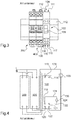
- the electronic card 560 of the electrical appliance 500 is here of the double-sided type, that is to say it comprises a first face 561 and a second face 562, each on one side of the electronic card 560.
- the shunt 555 On the first face 561 of the electronic card 560 is in particular arranged the shunt 555.
- this electronic card 560 On the second face 562 of this electronic card 560 are notably arranged the relay 551, the microcontroller that the logic unit 550 comprises, as well as a modem and the antenna 559 that the radiofrequency communication unit 554 comprises.
- the electronic card 560 is delimited by an upper face 570, a lower face 572, a front face 571 and a rear face.
- the connection terminals 522 and 520 are connected to the electronic card 560 at the level of the upper face and the connection terminals 513, 521 and 514 are connected to this card 560 at the level of the lower face 572.
- the key 509 is as for it connected to the electronic card by its front face 571.
- the electronic card 560 is configured to protect its internal circuit itself. Thus, it is not necessary to connect this circuit to a dedicated circuit breaker such as the circuit breaker 400 described above.
- the internal circuit of the apparatus 500 implemented by the card 560 comprises an input protection stage 547, generally shown on the diagram. figure 10 and in details on the figure 11 .
- the input protection stage 547 comprises a component 549 for protection against overcurrents, here a positive coefficient thermistor and a component 548 for protection against overvoltages, here a varistor.
- the component 549 for protection against overcurrents is arranged between its input and its output connected respectively to terminal 513 and to the corresponding input of the power supply 553.
- the component 548 for protection against overvoltage is disposed between the two outputs of the input protection stage 547.
- the input protection stage 547 also comprises a capacitor 5470 disposed in parallel with the component 548.
- the capacitor 5470 is useful for filtering the disturbances likely to be present in the alternating current source to which it is intended to connect the. terminals 513 and 514.
- the resistance of the thermistor 549 increases as a function of the temperature, which allows the circuit to be protected against short circuits, in particular in the event of a fault in the coil 556.
- the varistor 548 allows the absorption of fairly large voltage shocks, which allows protection of the circuit in particular against shocks due to lightning.
- the internal circuit of the apparatus 500 includes an output protection stage 540, shown generally in the figure. figure 10 and in details on the figure 12 .
- the output protection stage 540 is connected by a first side to the driver 544 as well as to the terminal 514 and by a second side to the terminals 520 and 522.
- the output protection stage 540 includes an overvoltage protection component 543, here a bipolar Zener diode, an overcurrent protection component 541, here a positive coefficient thermistor, and another overcurrent protection component 542. , here a positive coefficient thermistor.
- the component 541 for protection against overcurrents is arranged between its output and its input connected respectively to terminal 520 and to the corresponding output of the control member 544; the overcurrent protection component 542 is disposed between its output and its input connected respectively to terminal 522 and to the corresponding output of the control member; and the surge protection component 543 is disposed between the two inputs of the output protection stage 540.
- the output protection stage 540 serves to protect the internal circuit of the device 500 against wiring errors, for example the application of the mains voltage between terminals 520 and 522 by connecting one of these terminals to the neutral pole and the other terminal to the phase pole. Due to the protection offered by the input protection stage 547, in the circuit shown in figure 15 , where the electrical appliance 500 is a contactor, only a circuit breaker 600 identical to the circuit breaker 300 described above is provided.
- the terminal 522 is connected by a first cable 530 to a first side of the controller 523 and by a second cable 531 to the second side of the controller 523; and that the terminals 513, 521 and 514 are connected as explained above, by cables, to the circuit breaker 600 and to the load 524.
- the load 524 is not supplied; and when the controller 523 is in the on state, the load 524 is supplied.
- the device 500 is a remote control switch.
- this second embodiment is identical to the first embodiment except that the logic unit 550 is programmed differently: whereas in the first embodiment (contactor) the logic unit 550 is programmed so that the transitions of the switching device 557 between the off state and the on state follow the transitions between the off state and the on state of the control device such as 523, in the remote control switch, the logic unit 550 is programmed so that transitions of the switching device 557 between the off state and the on state follow only the transitions from the deactivated state to the activated state of the pilot element 544, and therefore only the transitions from the off state in the on state of the control unit such as 523.
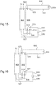
- circuit shown on figure 16 is identical to that shown on the figure 15 , except that the electrical appliance 500 is a remote control switch (and not a contactor) and that the control member 523 is identical to the control member 223 described above (and not to the control member 123).
- the second embodiment of the electrical device 500 which is a remote control switch, replaces a known remote control switch 200 which was part of a circuit as illustrated on figure 8 .
- the second embodiment of the electrical apparatus 500 which is a remote control switch, is thus associated with two circuit breakers of different amperages, in this case not only with the load protection circuit breaker 600 524 (which may be the circuit breaker 300 described. above), but also to the circuit breaker 400 described above.
- the terminal 522 is connected by a cable 580 to a first side of the control unit 523.
- the second side of the control unit 523 is connected to a starting terminal of the circuit breaker 400, here the terminal at the phase potential .
- the terminal 521 is connected by a cable 581 to the first side of the load 524.
- the second side of the load 524 is connected by a cable 582 to one of the outgoing terminals of the circuit breaker 600, here at neutral potential.
- Terminal 513 is connected by a cable to the same starting terminal of circuit breaker 600 as the second side of load 524 (here terminal at neutral potential).
- Terminal 524 is connected by a cable to the other outgoing terminal of circuit breaker 600 (here at phase potential).
- circuit shown on figure 17 is similar to the circuit shown on figure 16 including one side of actuator 523 which is wired to terminal 522, but the other side of the controller 523 is connected to the starting terminal of the circuit breaker 400 at the phase potential, and not to the terminal 520.
- terminal 520 Since terminal 520 is at phase potential, operation remains the same.
- the circuit is identical to that shown on the figure 17 , except that the apparatus 500 is according to the first embodiment, that is to say a contactor, and except that the controller 523 is identical to the controller 123 described above (and not to the control unit 223).
Landscapes
- Physics & Mathematics (AREA)
- Electromagnetism (AREA)
- Remote Monitoring And Control Of Power-Distribution Networks (AREA)
- Control Of Electrical Variables (AREA)
- Breakers (AREA)
- Emergency Protection Circuit Devices (AREA)
- Relay Circuits (AREA)
Claims (14)
- Elektrisches Gerät zum kabelgebundenen Anschließen an eine Wechselstromquelle für eine elektrische Haus- oder Gewerbeanlage, an eine Last (524) und an ein Steuerelement (523), um die Last (524) in Abhängigkeit von einem durch das Steuerelement (523) eingenommenen Ein- bzw. Aus-Zustand von der Wechselstromquelle versorgen zu lassen oder nicht, wobei das Gerät (500) enthält:- eine Zugangsanschlussklemme (514), die dazu ausgelegt ist, an einen Pol der Wechselstromquelle angeschlossen zu werden;- eine Abgangsanschlussklemme (521), die dazu ausgelegt ist, an die Last (524) angeschlossen zu werden; und- eine erste Steueranschlussklemme (522), die dazu ausgelegt ist, an das Steuerelement (523) angeschlossen zu werden, und eine zweite Steueranschlussklemme (520), die dazu ausgelegt ist, auf ein Bezugspotential gebracht zu werden, wobei die erste Steueranschlussklemme (522) und die zweite Steueranschlussklemme (520) so ausgelegt sind, dass in Abhängigkeit von dem von dem Steuerelement (523) eingenommenen Ein- bzw. Aus-Zustand eine vorbestimmte Potentialdifferenz an sie angelegt wird oder nicht;- ein Ansteuerglied (544), das mit der ersten Steueranschlussklemme (522) und mit der zweiten Steueranschlussklemme (520) verbunden ist und in Abhängigkeit vom Vorliegen bzw. Ausbleiben der vorbestimmten Potentialdifferenz zwischen der ersten Steueranschlussklemme (522) und der zweiten Steueranschlussklemme (520) selektiv einen aktivierten Zustand bzw. einen deaktivierten Zustand einnimmt; und- ein Schaltglied (557), das mit der Zugangsanschlussklemme (514) und mit der Abgangsanschlussklemme (521) verbunden ist und entweder einen Aus-Zustand, in dem es einen Stromfluss zwischen der Zugangsanschlussklemme (514) und der Abgangsanschlussklemme (521) verhindert, oder einen Ein-Zustand einnimmt, in dem es einen Stromfluss zwischen der Zugangsanschlussklemme (514) und der Abgangsanschlussklemme (521) zulässt, wobei das Schaltglied (557) über das Ansteuerglied (544) mittels einer Ansteuerübertragung angesteuert wird, die so ausgelegt ist, dass die Übergänge zwischen dem Aus-Zustand und dem Ein-Zustand des Schaltglieds (557) den Übergängen zwischen dem deaktivierten Zustand und dem aktivierten Zustand des Ansteuerglieds (544) folgen, oder so ausgelegt ist, dass die Übergänge zwischen dem Aus-Zustand und dem Ein-Zustand des Schaltglieds (557) nur den Übergängen von dem deaktivierten Zustand zu dem aktivierten Zustand folgen;wobei das Gerät dadurch gekennzeichnet ist, dass
es eine weitere Zugangsanschlussklemme (513) aufweist, die dazu ausgelegt ist, an den weiteren Pol der Wechselstromquelle angeschlossen zu werden, und einen Spannungswandler (553, 552) aufweist, der am Eingang mit der Zugangsanschlussklemme (514) und mit der weiteren Zugangsanschlussklemme (513) verbunden ist, um von der Wechselstromquelle versorgt zu werden, und am Ausgang mit dem Ansteuerglied (544) verbunden ist, um diesem eine Sicherheitsspannung bereitzustellen, die niedriger als 50 V bei Wechselstrom bzw. niedriger als 120 V bei Gleichstrom ist, wobei das Ansteuerglied (544) dazu ausgelegt ist, die Sicherheitsspannung zwischen der ersten Steueranschlussklemme (522) und der zweiten Steueranschlussklemme (520) anzulegen, wenn diese außerhalb des Geräts elektrisch voneinander isoliert sind, und die Sicherheitsspannung zwischen der ersten Steueranschlussklemme (522) und der zweiten Steueranschlussklemme (520) nicht anzulegen, wenn diese außerhalb des Geräts auf das gleiche Potential gebracht sind, wobei das Ansteuerglied in dem deaktivierten Zustand ist, wenn die erste Steueranschlussklemme (522) und die zweite Steueranschlussklemme (520) außerhalb des Geräts elektrisch voneinander isoliert sind, und in dem aktivierten Zustand ist, wenn die erste Steueranschlussklemme (522) und die zweite Steueranschlussklemme (520) außerhalb des Geräts auf das gleiche Potential gebracht sind, wobei das Ansteuerglied (544) eine elektrische Schaltung enthält, die ein logisches Signal bereitstellt, das aus zwei vorbestimmten Spannungsschwellenwerten gebildet ist, die jeweils den aktivierten Zustand bzw. den deaktivierten Zustand darstellen, wobei die Ansteuerübertragung eine Logikeinheit (550) enthält, die mit dem Ansteuerglied (544) verbunden ist, sowie einen elektromagnetischen Aktuator (556) des Schaltglieds (557), der mit der Logikeinheit (550) verbunden ist. - Gerät nach Anspruch 1,
dadurch gekennzeichnet, dass
der Spannungswandler (552, 553) so ausgelegt ist, dass die Sicherheitsspannungsquelle unter Gleichstrom vorliegt. - Gerät nach Anspruch 2,
dadurch gekennzeichnet, dass
das Ansteuerglied (544) einen Strombegrenzungswiderstand (545) aufweist, der auf einer Seite mit einem Ausgangspol des Spannungswandlers (552, 553) und auf der anderen Seite mit der ersten Steueranschlussklemme (522) verbunden ist. - Gerät nach Anspruch 3,
dadurch gekennzeichnet, dass
das Ansteuerglied (544) ferner einen Vorspannungswiderstand (546) aufweist, der zwischen der Logikeinheit (550) und der Seite des Strombegrenzungswiderstands (545) angeordnet ist, die mit der ersten Steueranschlussklemme (522) verbunden ist. - Gerät nach einem der Ansprüche 1 bis 4,
dadurch gekennzeichnet, dass
es eine Eingangsschutzstufe (547) aufweist, die zwischen der Zugangsanschlussklemme (514) und der weiteren Zugangsanschlussklemme (513) einerseits und dem Sicherheitsspannungswandler (552, 553) andererseits angeordnet ist, wobei die Eingangsschutzstufe (547) ein Element (549) zum Schutz gegen Überströme und ein Element (548) zum Schutz gegen Überspannungen aufweist. - Gerät nach Anspruch 5,
dadurch gekennzeichnet, dass
das Überstrom-Schutzelement ein Thermistor (549) mit positivem Koeffizienten ist und das Überspannungs-Schutzelement ein Varistor (548) ist. - Gerät nach einem der Ansprüche 1 bis 6,
dadurch gekennzeichnet, dass
es eine Ausgangsschutzstufe (540) aufweist, die zwischen der ersten Steueranschlussklemme (522) und der zweiten Steueranschlussklemme (520) einerseits und dem Ansteuerglied (544) andererseits angeordnet ist, wobei die Ausgangsschutzstufe (540) zumindest ein Element (541, 542) zum Schutz gegen Überströme und ein Element (543) zum Schutz gegen Überspannungen aufweist. - Gerät nach Anspruch 7,
dadurch gekennzeichnet, dass
das Überstrom-Schutzelement ein Thermistor (541, 542) mit positivem Koeffizienten ist und das Überspannungs-Schutzelement eine bidirektionale Zenerdiode (543) ist. - Gerät nach einem der Ansprüche 1 bis 8,
dadurch gekennzeichnet, dass
es ein Hochfrequenz-Kommunikationselement (554) umfasst, das mit der Logikeinheit (550) verbunden ist. - Gerät nach einem der Ansprüche 1 bis 9,
dadurch gekennzeichnet, dass
das Schaltglied ein Paar von Kontakten (557) ist und zu einem elektromagnetischen Relais (551) gehört, das eine Spule (556) und eine mechanische Übertragung (568) zwischen der Spule (556) und dem Paar von Kontakten (557) aufweist. - Gerät nach einem der Ansprüche 1 bis 10,
dadurch gekennzeichnet, dass
es ein Strommesselement aufweist, das zwischen der Zugangsanschlussklemme (514) und der Abgangsanschlussklemme (521) angeordnet und mit der Logikeinheit (550) verbunden ist. - Gerät nach Anspruch 11,
dadurch gekennzeichnet, dass
das Strommesselement ein Shunt (555) ist. - Elektrische Schaltung, enthaltend ein Gerät nach einem der Ansprüche 1 bis 12, zumindest ein Steuerelement (523), das zum Steuern zumindest einer Last (524) ausgelegt ist, und einen Leistungsschalter (600), dadurch gekennzeichnet, dass:- das Steuerelement (523) mit seiner ersten Seite an die erste Steueranschlussklemme (522) und mit seiner zweiten Seite an die zweite Steueranschlussklemme (520) des Geräts (500) angeschlossen ist;- die Last (524) mit ihrer ersten Seite an die Abgangsanschlussklemme (521) des Geräts (500) und mit ihrer zweiten Seite an eine Anschlussklemme des Leistungsschalters (600) angeschlossen ist; und- die Zugangsanschlussklemme (514) und die weitere Zugangsanschlussklemme (513) des Geräts (500) jeweils an eine Anschlussklemme des Leistungsschalters (600) angeschlossen sind.
- Elektrische Schaltung, enthaltend ein Gerät nach einem der Ansprüche 1 bis 12, zumindest ein Steuerelement (523), das zum Steuern zumindest einer Last (524) ausgelegt ist, einen ersten Leistungsschalter (600) und einen zweiten Leistungsschalter (400),
dadurch gekennzeichnet, dass:- das Steuerelement (523) mit seiner ersten Seite an die erste Steueranschlussklemme (522) des Geräts (500) und mit seiner zweiten Seite an eine Anschlussklemme des zweiten Leistungsschalters (400) angeschlossen ist;- die Last mit ihrer ersten Seite an die Abgangsanschlussklemme (521) des Geräts (500) und mit ihrer zweiten Seite an eine Anschlussklemme des ersten Leistungsschalters (600) angeschlossen ist; und- die Zugangsanschlussklemme (514) und die weitere Zugangsanschlussklemme (513) des Geräts (500) jeweils an eine Anschlussklemme des ersten Leistungsschalters (600) angeschlossen sind.
Priority Applications (1)
| Application Number | Priority Date | Filing Date | Title |
|---|---|---|---|
| PL20162897T PL3709333T3 (pl) | 2019-03-14 | 2020-03-13 | Elektryczne urządzenie do zasilania, albo nie, obciążenia w zależności od stanu przewodzenia albo blokowania przewodzenia elementu sterującego |
Applications Claiming Priority (1)
| Application Number | Priority Date | Filing Date | Title |
|---|---|---|---|
| FR1902635A FR3093869B1 (fr) | 2019-03-14 | 2019-03-14 | Appareil électrique pour alimenter ou non une charge en fonction de l’état passant ou bloqué d’un organe de commande |
Publications (2)
| Publication Number | Publication Date |
|---|---|
| EP3709333A1 EP3709333A1 (de) | 2020-09-16 |
| EP3709333B1 true EP3709333B1 (de) | 2021-09-08 |
Family
ID=67514797
Family Applications (1)
| Application Number | Title | Priority Date | Filing Date |
|---|---|---|---|
| EP20162897.1A Active EP3709333B1 (de) | 2019-03-14 | 2020-03-13 | Elektrisches gerät zur versorgung oder nichtversorgung einer last in abhängigkeit vom ein- oder aus-zustand eines bedienorgans |
Country Status (6)
| Country | Link |
|---|---|
| EP (1) | EP3709333B1 (de) |
| CN (1) | CN111696829B (de) |
| AU (1) | AU2020201831B2 (de) |
| ES (1) | ES2895348T3 (de) |
| FR (1) | FR3093869B1 (de) |
| PL (1) | PL3709333T3 (de) |
Families Citing this family (2)
| Publication number | Priority date | Publication date | Assignee | Title |
|---|---|---|---|---|
| FR3121545B1 (fr) | 2021-04-01 | 2024-05-03 | Legrand France | Appareil électrique |
| FR3129245B1 (fr) | 2021-11-12 | 2023-11-03 | Hager Electro Sas | Module auxiliaire pour un appareil électrique |
Family Cites Families (13)
| Publication number | Priority date | Publication date | Assignee | Title |
|---|---|---|---|---|
| US5689395A (en) * | 1995-09-14 | 1997-11-18 | Raychem Corporation | Overcurrent protection circuit |
| JP4288868B2 (ja) * | 2001-05-28 | 2009-07-01 | 富士電機機器制御株式会社 | 回路しゃ断器の付属スイッチ装置 |
| DE102006010106A1 (de) * | 2006-03-01 | 2007-09-06 | Pilz Gmbh & Co. Kg | Sicherheitsschaltvorrichtung zum fehlersicheren Abschalten eines elektrischen Verbrauchers |
| FR2906075B1 (fr) | 2006-09-18 | 2009-08-07 | Legrand France | Mecanisme a deux positions stables et dispositif |
| CN101662216A (zh) * | 2008-08-26 | 2010-03-03 | 克立欧电子有限公司 | 电压变换器用安全输出装置及具有该装置的电压变换器 |
| DE102010007784A1 (de) * | 2010-02-12 | 2011-08-18 | FESTO AG & Co. KG, 73734 | Vorrichtung zur elektrischen Stromkreisüberwachung |
| FR2978862B1 (fr) * | 2011-08-01 | 2013-09-27 | Legrand France | Appareil electrique comportant deux bornes de commande pour mettre un organe mobile selectivement en position de repos et en position de travail |
| US8853893B2 (en) * | 2011-11-02 | 2014-10-07 | Pass & Seymour, Inc. | Electrical wiring device for lighting control |
| FR2986104B1 (fr) * | 2012-01-23 | 2015-06-05 | Legrand France | Appareil electrique au format modulaire |
| US9680269B2 (en) * | 2013-08-08 | 2017-06-13 | Lennox Industries Inc. | Electrical contactor with header connectors |
| FR3046289B1 (fr) * | 2015-12-29 | 2018-02-16 | Legrand France | Appareil electrique de protection au format modulaire |
| FR3046890B1 (fr) * | 2016-01-15 | 2019-05-03 | Schneider Electric Industries Sas | Dispositif d'alimentation electrique |
| KR20170113836A (ko) * | 2016-03-28 | 2017-10-13 | 주식회사 엠알티 | 직류전원 단로기의 접점 보호와 차단 및 재투입장치 |
-
2019
- 2019-03-14 FR FR1902635A patent/FR3093869B1/fr not_active Expired - Fee Related
-
2020
- 2020-03-12 AU AU2020201831A patent/AU2020201831B2/en active Active
- 2020-03-13 EP EP20162897.1A patent/EP3709333B1/de active Active
- 2020-03-13 PL PL20162897T patent/PL3709333T3/pl unknown
- 2020-03-13 CN CN202010173100.XA patent/CN111696829B/zh active Active
- 2020-03-13 ES ES20162897T patent/ES2895348T3/es active Active
Also Published As
| Publication number | Publication date |
|---|---|
| EP3709333A1 (de) | 2020-09-16 |
| ES2895348T3 (es) | 2022-02-21 |
| PL3709333T3 (pl) | 2022-01-31 |
| FR3093869A1 (fr) | 2020-09-18 |
| AU2020201831A1 (en) | 2020-10-01 |
| CN111696829B (zh) | 2024-08-09 |
| AU2020201831B2 (en) | 2024-10-03 |
| CN111696829A (zh) | 2020-09-22 |
| FR3093869B1 (fr) | 2021-04-09 |
| RU2020110708A (ru) | 2021-09-13 |
Similar Documents
| Publication | Publication Date | Title |
|---|---|---|
| EP1449287B1 (de) | Steuer und schutzmodul eines schaltgeräts | |
| EP3709333B1 (de) | Elektrisches gerät zur versorgung oder nichtversorgung einer last in abhängigkeit vom ein- oder aus-zustand eines bedienorgans | |
| EP0096601A1 (de) | Funktioneller Niederspannungs-Energieverteilungsblock | |
| EP3809441B1 (de) | Schutzgerät einer elektrischen anlage mit wechselstrom | |
| EP4068327B1 (de) | Elektrisches gerät, mit dem eine wechselstromquelle je nach den über eine funkfrequenz empfangenen befehlen eine last speisen kann oder nicht, und schaltkreis mit diesem gerät | |
| BE1005336A0 (fr) | Telerupteur a dispositif de limitation de courant. | |
| EP0079271A1 (de) | Abzweigschalter mit Leistungskontrolle durch einen Steuermodul | |
| EP0320409B1 (de) | Statischer Auslöser mit externer Versorgung | |
| EP0018867A2 (de) | Geschützte thyristorbestückte Stromzufuhr | |
| EP2555216B1 (de) | Elektrogerät, das mit zwei Steuerklemmen ausgestattet ist, um ein mobiles Organ wahlweise in Ruhe- oder Arbeitsstellung zu versetzen | |
| EP0614259B1 (de) | Differenzstromschalter zum Schutz gegen Fehlerströme und Überspannungen | |
| EP0079270B1 (de) | Niederspannungsabzweigschalter mit einem ferngesteuerten Einstellschalter | |
| EP3809440B1 (de) | Schutzgerät einer elektrischen anlage mit wechselstrom | |
| EP0898366A1 (de) | Elektronischer Unterbrecher | |
| EP4181165B1 (de) | Hilfsmodul für ein elektrisches gerät | |
| RU2798773C2 (ru) | Электрическое устройство для подключения или отключения питания нагрузки в зависимости от проводящего или непроводящего состояния командного элемента | |
| EP2693585B1 (de) | Schutzsystem für eine Vielzahl von elektrischen Ableitungen gegen Kurzschlüsse, und Elektroanlage, die ein solches Schutzsystem umfasst | |
| FR2893196A1 (fr) | Appareil electrique de protection contre les surtensions transitoires | |
| EP0755107A1 (de) | Nachrichtenkreis für Fehlermeldung und zugehöriges Testmodul | |
| EP0105786A1 (de) | Abzweigschalter mit einem elektronischen Auslöser und einer ferngesteuerten Einstellung | |
| FR2466893A2 (fr) | Reseau de distribution electrique avec telereglage des disjoncteurs de puissance | |
| CH468736A (fr) | Bloc d'éclairage de sécurité | |
| FR2495823A1 (fr) | Interrupteur automatique a enclenchement temporise aleatoirement et dispositifs de protection derives | |
| FR2671917A1 (fr) | Systeme pour la commande de l'alimentation en energie electrique et la protection d'un dispositif recepteur electrique. |
Legal Events
| Date | Code | Title | Description |
|---|---|---|---|
| PUAI | Public reference made under article 153(3) epc to a published international application that has entered the european phase |
Free format text: ORIGINAL CODE: 0009012 |
|
| STAA | Information on the status of an ep patent application or granted ep patent |
Free format text: STATUS: THE APPLICATION HAS BEEN PUBLISHED |
|
| AK | Designated contracting states |
Kind code of ref document: A1 Designated state(s): AL AT BE BG CH CY CZ DE DK EE ES FI FR GB GR HR HU IE IS IT LI LT LU LV MC MK MT NL NO PL PT RO RS SE SI SK SM TR |
|
| AX | Request for extension of the european patent |
Extension state: BA ME |
|
| STAA | Information on the status of an ep patent application or granted ep patent |
Free format text: STATUS: REQUEST FOR EXAMINATION WAS MADE |
|
| 17P | Request for examination filed |
Effective date: 20201127 |
|
| RBV | Designated contracting states (corrected) |
Designated state(s): AL AT BE BG CH CY CZ DE DK EE ES FI FR GB GR HR HU IE IS IT LI LT LU LV MC MK MT NL NO PL PT RO RS SE SI SK SM TR |
|
| GRAP | Despatch of communication of intention to grant a patent |
Free format text: ORIGINAL CODE: EPIDOSNIGR1 |
|
| STAA | Information on the status of an ep patent application or granted ep patent |
Free format text: STATUS: GRANT OF PATENT IS INTENDED |
|
| INTG | Intention to grant announced |
Effective date: 20210408 |
|
| GRAS | Grant fee paid |
Free format text: ORIGINAL CODE: EPIDOSNIGR3 |
|
| GRAA | (expected) grant |
Free format text: ORIGINAL CODE: 0009210 |
|
| STAA | Information on the status of an ep patent application or granted ep patent |
Free format text: STATUS: THE PATENT HAS BEEN GRANTED |
|
| AK | Designated contracting states |
Kind code of ref document: B1 Designated state(s): AL AT BE BG CH CY CZ DE DK EE ES FI FR GB GR HR HU IE IS IT LI LT LU LV MC MK MT NL NO PL PT RO RS SE SI SK SM TR |
|
| REG | Reference to a national code |
Ref country code: GB Ref legal event code: FG4D Free format text: NOT ENGLISH |
|
| REG | Reference to a national code |
Ref country code: CH Ref legal event code: EP Ref country code: AT Ref legal event code: REF Ref document number: 1429331 Country of ref document: AT Kind code of ref document: T Effective date: 20210915 |
|
| REG | Reference to a national code |
Ref country code: IE Ref legal event code: FG4D Free format text: LANGUAGE OF EP DOCUMENT: FRENCH |
|
| REG | Reference to a national code |
Ref country code: DE Ref legal event code: R096 Ref document number: 602020000500 Country of ref document: DE |
|
| REG | Reference to a national code |
Ref country code: LT Ref legal event code: MG9D |
|
| REG | Reference to a national code |
Ref country code: NL Ref legal event code: MP Effective date: 20210908 |
|
| PG25 | Lapsed in a contracting state [announced via postgrant information from national office to epo] |
Ref country code: RS Free format text: LAPSE BECAUSE OF FAILURE TO SUBMIT A TRANSLATION OF THE DESCRIPTION OR TO PAY THE FEE WITHIN THE PRESCRIBED TIME-LIMIT Effective date: 20210908 Ref country code: SE Free format text: LAPSE BECAUSE OF FAILURE TO SUBMIT A TRANSLATION OF THE DESCRIPTION OR TO PAY THE FEE WITHIN THE PRESCRIBED TIME-LIMIT Effective date: 20210908 Ref country code: LT Free format text: LAPSE BECAUSE OF FAILURE TO SUBMIT A TRANSLATION OF THE DESCRIPTION OR TO PAY THE FEE WITHIN THE PRESCRIBED TIME-LIMIT Effective date: 20210908 Ref country code: BG Free format text: LAPSE BECAUSE OF FAILURE TO SUBMIT A TRANSLATION OF THE DESCRIPTION OR TO PAY THE FEE WITHIN THE PRESCRIBED TIME-LIMIT Effective date: 20211208 Ref country code: NO Free format text: LAPSE BECAUSE OF FAILURE TO SUBMIT A TRANSLATION OF THE DESCRIPTION OR TO PAY THE FEE WITHIN THE PRESCRIBED TIME-LIMIT Effective date: 20211208 Ref country code: HR Free format text: LAPSE BECAUSE OF FAILURE TO SUBMIT A TRANSLATION OF THE DESCRIPTION OR TO PAY THE FEE WITHIN THE PRESCRIBED TIME-LIMIT Effective date: 20210908 Ref country code: FI Free format text: LAPSE BECAUSE OF FAILURE TO SUBMIT A TRANSLATION OF THE DESCRIPTION OR TO PAY THE FEE WITHIN THE PRESCRIBED TIME-LIMIT Effective date: 20210908 |
|
| REG | Reference to a national code |
Ref country code: AT Ref legal event code: MK05 Ref document number: 1429331 Country of ref document: AT Kind code of ref document: T Effective date: 20210908 |
|
| REG | Reference to a national code |
Ref country code: ES Ref legal event code: FG2A Ref document number: 2895348 Country of ref document: ES Kind code of ref document: T3 Effective date: 20220221 |
|
| PG25 | Lapsed in a contracting state [announced via postgrant information from national office to epo] |
Ref country code: LV Free format text: LAPSE BECAUSE OF FAILURE TO SUBMIT A TRANSLATION OF THE DESCRIPTION OR TO PAY THE FEE WITHIN THE PRESCRIBED TIME-LIMIT Effective date: 20210908 Ref country code: GR Free format text: LAPSE BECAUSE OF FAILURE TO SUBMIT A TRANSLATION OF THE DESCRIPTION OR TO PAY THE FEE WITHIN THE PRESCRIBED TIME-LIMIT Effective date: 20211209 |
|
| PG25 | Lapsed in a contracting state [announced via postgrant information from national office to epo] |
Ref country code: AT Free format text: LAPSE BECAUSE OF FAILURE TO SUBMIT A TRANSLATION OF THE DESCRIPTION OR TO PAY THE FEE WITHIN THE PRESCRIBED TIME-LIMIT Effective date: 20210908 |
|
| PG25 | Lapsed in a contracting state [announced via postgrant information from national office to epo] |
Ref country code: IS Free format text: LAPSE BECAUSE OF FAILURE TO SUBMIT A TRANSLATION OF THE DESCRIPTION OR TO PAY THE FEE WITHIN THE PRESCRIBED TIME-LIMIT Effective date: 20220108 Ref country code: SM Free format text: LAPSE BECAUSE OF FAILURE TO SUBMIT A TRANSLATION OF THE DESCRIPTION OR TO PAY THE FEE WITHIN THE PRESCRIBED TIME-LIMIT Effective date: 20210908 Ref country code: SK Free format text: LAPSE BECAUSE OF FAILURE TO SUBMIT A TRANSLATION OF THE DESCRIPTION OR TO PAY THE FEE WITHIN THE PRESCRIBED TIME-LIMIT Effective date: 20210908 Ref country code: RO Free format text: LAPSE BECAUSE OF FAILURE TO SUBMIT A TRANSLATION OF THE DESCRIPTION OR TO PAY THE FEE WITHIN THE PRESCRIBED TIME-LIMIT Effective date: 20210908 Ref country code: PT Free format text: LAPSE BECAUSE OF FAILURE TO SUBMIT A TRANSLATION OF THE DESCRIPTION OR TO PAY THE FEE WITHIN THE PRESCRIBED TIME-LIMIT Effective date: 20220110 Ref country code: NL Free format text: LAPSE BECAUSE OF FAILURE TO SUBMIT A TRANSLATION OF THE DESCRIPTION OR TO PAY THE FEE WITHIN THE PRESCRIBED TIME-LIMIT Effective date: 20210908 Ref country code: EE Free format text: LAPSE BECAUSE OF FAILURE TO SUBMIT A TRANSLATION OF THE DESCRIPTION OR TO PAY THE FEE WITHIN THE PRESCRIBED TIME-LIMIT Effective date: 20210908 Ref country code: CZ Free format text: LAPSE BECAUSE OF FAILURE TO SUBMIT A TRANSLATION OF THE DESCRIPTION OR TO PAY THE FEE WITHIN THE PRESCRIBED TIME-LIMIT Effective date: 20210908 Ref country code: AL Free format text: LAPSE BECAUSE OF FAILURE TO SUBMIT A TRANSLATION OF THE DESCRIPTION OR TO PAY THE FEE WITHIN THE PRESCRIBED TIME-LIMIT Effective date: 20210908 |
|
| REG | Reference to a national code |
Ref country code: DE Ref legal event code: R097 Ref document number: 602020000500 Country of ref document: DE |
|
| PLBE | No opposition filed within time limit |
Free format text: ORIGINAL CODE: 0009261 |
|
| STAA | Information on the status of an ep patent application or granted ep patent |
Free format text: STATUS: NO OPPOSITION FILED WITHIN TIME LIMIT |
|
| PG25 | Lapsed in a contracting state [announced via postgrant information from national office to epo] |
Ref country code: DK Free format text: LAPSE BECAUSE OF FAILURE TO SUBMIT A TRANSLATION OF THE DESCRIPTION OR TO PAY THE FEE WITHIN THE PRESCRIBED TIME-LIMIT Effective date: 20210908 |
|
| 26N | No opposition filed |
Effective date: 20220609 |
|
| PG25 | Lapsed in a contracting state [announced via postgrant information from national office to epo] |
Ref country code: SI Free format text: LAPSE BECAUSE OF FAILURE TO SUBMIT A TRANSLATION OF THE DESCRIPTION OR TO PAY THE FEE WITHIN THE PRESCRIBED TIME-LIMIT Effective date: 20210908 |
|
| PG25 | Lapsed in a contracting state [announced via postgrant information from national office to epo] |
Ref country code: MC Free format text: LAPSE BECAUSE OF FAILURE TO SUBMIT A TRANSLATION OF THE DESCRIPTION OR TO PAY THE FEE WITHIN THE PRESCRIBED TIME-LIMIT Effective date: 20210908 |
|
| PG25 | Lapsed in a contracting state [announced via postgrant information from national office to epo] |
Ref country code: LU Free format text: LAPSE BECAUSE OF NON-PAYMENT OF DUE FEES Effective date: 20220313 Ref country code: IE Free format text: LAPSE BECAUSE OF NON-PAYMENT OF DUE FEES Effective date: 20220313 |
|
| P01 | Opt-out of the competence of the unified patent court (upc) registered |
Effective date: 20230515 |
|
| PG25 | Lapsed in a contracting state [announced via postgrant information from national office to epo] |
Ref country code: MK Free format text: LAPSE BECAUSE OF FAILURE TO SUBMIT A TRANSLATION OF THE DESCRIPTION OR TO PAY THE FEE WITHIN THE PRESCRIBED TIME-LIMIT Effective date: 20210908 Ref country code: CY Free format text: LAPSE BECAUSE OF FAILURE TO SUBMIT A TRANSLATION OF THE DESCRIPTION OR TO PAY THE FEE WITHIN THE PRESCRIBED TIME-LIMIT Effective date: 20210908 |
|
| PG25 | Lapsed in a contracting state [announced via postgrant information from national office to epo] |
Ref country code: HU Free format text: LAPSE BECAUSE OF FAILURE TO SUBMIT A TRANSLATION OF THE DESCRIPTION OR TO PAY THE FEE WITHIN THE PRESCRIBED TIME-LIMIT; INVALID AB INITIO Effective date: 20200313 |
|
| PG25 | Lapsed in a contracting state [announced via postgrant information from national office to epo] |
Ref country code: TR Free format text: LAPSE BECAUSE OF FAILURE TO SUBMIT A TRANSLATION OF THE DESCRIPTION OR TO PAY THE FEE WITHIN THE PRESCRIBED TIME-LIMIT Effective date: 20210908 |
|
| PG25 | Lapsed in a contracting state [announced via postgrant information from national office to epo] |
Ref country code: MT Free format text: LAPSE BECAUSE OF FAILURE TO SUBMIT A TRANSLATION OF THE DESCRIPTION OR TO PAY THE FEE WITHIN THE PRESCRIBED TIME-LIMIT Effective date: 20210908 |
|
| GBPC | Gb: european patent ceased through non-payment of renewal fee |
Effective date: 20240313 |
|
| PG25 | Lapsed in a contracting state [announced via postgrant information from national office to epo] |
Ref country code: GB Free format text: LAPSE BECAUSE OF NON-PAYMENT OF DUE FEES Effective date: 20240313 |
|
| PG25 | Lapsed in a contracting state [announced via postgrant information from national office to epo] |
Ref country code: GB Free format text: LAPSE BECAUSE OF NON-PAYMENT OF DUE FEES Effective date: 20240313 |
|
| PGFP | Annual fee paid to national office [announced via postgrant information from national office to epo] |
Ref country code: DE Payment date: 20250218 Year of fee payment: 6 |
|
| PGFP | Annual fee paid to national office [announced via postgrant information from national office to epo] |
Ref country code: BE Payment date: 20250218 Year of fee payment: 6 |
|
| PGFP | Annual fee paid to national office [announced via postgrant information from national office to epo] |
Ref country code: FR Payment date: 20250218 Year of fee payment: 6 Ref country code: PL Payment date: 20250225 Year of fee payment: 6 |
|
| PGFP | Annual fee paid to national office [announced via postgrant information from national office to epo] |
Ref country code: IT Payment date: 20250218 Year of fee payment: 6 |
|
| PGFP | Annual fee paid to national office [announced via postgrant information from national office to epo] |
Ref country code: ES Payment date: 20250401 Year of fee payment: 6 |
|
| PGFP | Annual fee paid to national office [announced via postgrant information from national office to epo] |
Ref country code: CH Payment date: 20250401 Year of fee payment: 6 |