EP0341024A2 - Geteilte Konfiguration für Flugzeug mit Turboproptriebwerk - Google Patents
Geteilte Konfiguration für Flugzeug mit Turboproptriebwerk Download PDFInfo
- Publication number
- EP0341024A2 EP0341024A2 EP89304405A EP89304405A EP0341024A2 EP 0341024 A2 EP0341024 A2 EP 0341024A2 EP 89304405 A EP89304405 A EP 89304405A EP 89304405 A EP89304405 A EP 89304405A EP 0341024 A2 EP0341024 A2 EP 0341024A2
- Authority
- EP
- European Patent Office
- Prior art keywords
- wing
- engine
- turbo
- prop
- aircraft according
- Prior art date
- Legal status (The legal status is an assumption and is not a legal conclusion. Google has not performed a legal analysis and makes no representation as to the accuracy of the status listed.)
- Withdrawn
Links
Images
Classifications
-
- B—PERFORMING OPERATIONS; TRANSPORTING
- B64—AIRCRAFT; AVIATION; COSMONAUTICS
- B64D—EQUIPMENT FOR FITTING IN OR TO AIRCRAFT; FLIGHT SUITS; PARACHUTES; ARRANGEMENT OR MOUNTING OF POWER PLANTS OR PROPULSION TRANSMISSIONS IN AIRCRAFT
- B64D35/00—Transmitting power from power plants to propellers or rotors; Arrangements of transmissions
- B64D35/02—Transmitting power from power plants to propellers or rotors; Arrangements of transmissions specially adapted for specific power plants
-
- B—PERFORMING OPERATIONS; TRANSPORTING
- B64—AIRCRAFT; AVIATION; COSMONAUTICS
- B64D—EQUIPMENT FOR FITTING IN OR TO AIRCRAFT; FLIGHT SUITS; PARACHUTES; ARRANGEMENT OR MOUNTING OF POWER PLANTS OR PROPULSION TRANSMISSIONS IN AIRCRAFT
- B64D27/00—Arrangement or mounting of power plants in aircraft; Aircraft characterised by the type or position of power plants
- B64D27/02—Aircraft characterised by the type or position of power plants
- B64D27/04—Aircraft characterised by the type or position of power plants of piston type
- B64D27/06—Aircraft characterised by the type or position of power plants of piston type within, or attached to, wings
-
- B—PERFORMING OPERATIONS; TRANSPORTING
- B64—AIRCRAFT; AVIATION; COSMONAUTICS
- B64D—EQUIPMENT FOR FITTING IN OR TO AIRCRAFT; FLIGHT SUITS; PARACHUTES; ARRANGEMENT OR MOUNTING OF POWER PLANTS OR PROPULSION TRANSMISSIONS IN AIRCRAFT
- B64D35/00—Transmitting power from power plants to propellers or rotors; Arrangements of transmissions
- B64D35/04—Transmitting power from power plants to propellers or rotors; Arrangements of transmissions characterised by the transmission driving a plurality of propellers or rotors
- B64D35/06—Transmitting power from power plants to propellers or rotors; Arrangements of transmissions characterised by the transmission driving a plurality of propellers or rotors the propellers or rotors being counter-rotating
-
- Y—GENERAL TAGGING OF NEW TECHNOLOGICAL DEVELOPMENTS; GENERAL TAGGING OF CROSS-SECTIONAL TECHNOLOGIES SPANNING OVER SEVERAL SECTIONS OF THE IPC; TECHNICAL SUBJECTS COVERED BY FORMER USPC CROSS-REFERENCE ART COLLECTIONS [XRACs] AND DIGESTS
- Y02—TECHNOLOGIES OR APPLICATIONS FOR MITIGATION OR ADAPTATION AGAINST CLIMATE CHANGE
- Y02T—CLIMATE CHANGE MITIGATION TECHNOLOGIES RELATED TO TRANSPORTATION
- Y02T50/00—Aeronautics or air transport
- Y02T50/40—Weight reduction
Definitions
- This invention relates to turbo-prop powered aircraft.
- GB-A-621,606 and GB-A-621,607 disclose an engine arrangement in which the core engine is separated from the propeller assembly and connected thereto by means of an extended drive shaft.
- the engines are located in-recesses formed within the structural wing box which as already stated is undesirable, with the propeller assembly being a pusher propeller located behind the wing, and this arrangement does not meet the required safety standards in the event of a catastrophic engine failure.
- an aircraft including at least two wing-mounted turbo-prop powerplant installations, each wing including a spanwise extending structural wing box, a leading edge portion, and a tralling edge portion, each said turbo-prop including a gearbox/propeller assembly and said engine being spatially separated in fore and aft alignment with respect to said wing, characterised in that said engine is displaced away from said wing box.
- the fore and aft location of the separated engine and gearbox/propeller assemblies is such that the centre of gravity of each powerplant installation is beneficially located in the vicinity of the wing flexural axis.
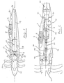
- the rearwardly convergent surface 15 of the centre body 13 forms the inner profile of an annular air intake duct 16 whose outer profile 17 is formed as an integral part of the integrated engine nacelle 18 for the supply of intake air to the core engine 6.
- the nacelle extends rearwardly as shown and includes an integral jet pipe 19 terminating in a thrust nozzle 20 rearward of the wing trailing edge 21.
- the overall powerplant assemblies centre of gravity is indicated at 22.
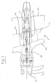
- Figure 3 illustrates in partial plan view a portion of an aircraft wing incorporating a turbo-prop powerplant configuration in accordance with the present invention and which may best be described as a split turbo-prop configuration. It will be understood that although only a single turbo-prop installation is illustrated for the purposes of description, this represents a twin engined aircraft configuration, it is also equally applicable to four engine configurations. Furthermore, the present invention, although specifically described in the context of a contra-rotating propeller installation, is equally applicable to single bladed propellers and may be beneficially relevant to aircraft of moderate wing leading edge sweep as illustrated or to more highly swept configurations.
- FIG 3 there is shown a portion of a wing 2 having a leading edge 25 and a trailing edge 26 both of moderate sweep back.
- the wing incorporates a structural wing box 4, shown in broken line.
- a structural wing box 4 shown in broken line.
- the aircraft of split engine configuration includes a core engine 6 positioned rearwards or aft of the wing box 4 and the propeller/gearbox assembly 10 well forwards of the wing box driven by a high speed (engine rpm) drive shaft 27.
- the gearbox/propeller assembly 10 is supported on a wing pylon 35 giving a considerably reduced moment arm over the arrangement of Figure 1 thereby increasing the stiffness of the gearbox/propeller installation and minimising induced vibration problems.
- This arrangement furthermore provides freedom to locate propellers in a position to provide minimum interface clearance with respect to the wing for aerodynamic reasons.
- the core engine 6 is supported off the structural wing box 4 by means of fore and aft attachments 28 and 29 respectively, the main attachment 28 positioned comparatively close to the wing box rear spar 30, the rear attachment 29 catering only for nodding loads.
- the drive shaft 27 is supported at a number of points along its length from the wing pylon 35 by means of bearings 36.
- the drive shaft 27 itself comprises a series of separate drive shaft elements 37 interconnected by means of flexible couplings 38. This drive shaft construction allows for any slight misalignments that may be caused by manufacturing tolerances or induced flight loads and vibrations, and provides improved installation.
- the split turbo-prop installation is contained within an integrated nacelle 31 incorporating engine air intakes 32 disposed in front of the engine 6 on either side of the drive shaft 27, and the nacelle is 'area ruled' to reduce drag at high speeds.
- the split engine concept provides available space in the vicinity of the air intake enabling more flexibility in intake design than hitherto and a consequent benefit from ram from the propeller slipstream.
- the clearly defined fire zone 33 is positioned well downstream of the wing box 4 and therefore the fuel tank, and is separated by means of a firewall 34.
Landscapes
- Engineering & Computer Science (AREA)
- Mechanical Engineering (AREA)
- Aviation & Aerospace Engineering (AREA)
- Structures Of Non-Positive Displacement Pumps (AREA)
- Wind Motors (AREA)
- Toys (AREA)
- Supercharger (AREA)
Applications Claiming Priority (2)
| Application Number | Priority Date | Filing Date | Title |
|---|---|---|---|
| GB888810616A GB8810616D0 (en) | 1988-05-05 | 1988-05-05 | Aircraft of split turboprop configuration |
| GB8810616 | 1988-05-05 |
Publications (2)
| Publication Number | Publication Date |
|---|---|
| EP0341024A2 true EP0341024A2 (de) | 1989-11-08 |
| EP0341024A3 EP0341024A3 (de) | 1990-08-22 |
Family
ID=10636384
Family Applications (1)
| Application Number | Title | Priority Date | Filing Date |
|---|---|---|---|
| EP89304405A Withdrawn EP0341024A3 (de) | 1988-05-05 | 1989-05-02 | Geteilte Konfiguration für Flugzeug mit Turboproptriebwerk |
Country Status (3)
| Country | Link |
|---|---|
| US (1) | US4998995A (de) |
| EP (1) | EP0341024A3 (de) |
| GB (1) | GB8810616D0 (de) |
Cited By (1)
| Publication number | Priority date | Publication date | Assignee | Title |
|---|---|---|---|---|
| WO1999058852A1 (en) | 1998-05-13 | 1999-11-18 | Otarid Consult Limited | Method of creation of forces for movement of vehicles and device for its embodiment |
Families Citing this family (13)
| Publication number | Priority date | Publication date | Assignee | Title |
|---|---|---|---|---|
| US5699662A (en) * | 1996-05-28 | 1997-12-23 | Lockheed Martin Corporation | Infrared suppression exhaust duct system for a turboprop propulsion system for an aircraft |
| US6367738B1 (en) * | 2000-01-31 | 2002-04-09 | John Wadleigh | Aerobatic aircraft |
| DE10040577B4 (de) * | 2000-08-18 | 2006-02-23 | König, Helmut, Ing. | Antriebseinrichtung für Flugzeuge |
| DE10305352A1 (de) * | 2003-02-10 | 2004-09-02 | Rolls-Royce Deutschland Ltd & Co Kg | Turbopropantrieb mit mitläufigem Zweistufenhochleistungspropeller |
| US6883750B2 (en) * | 2003-07-16 | 2005-04-26 | Sikorsky Aircraft Corporation | Split torque gearbox with pivoted engine support |
| US10272997B1 (en) * | 2007-10-22 | 2019-04-30 | Abe Karem | Structural enclosure for an aircraft propulsion system |
| US8701381B2 (en) | 2010-11-24 | 2014-04-22 | Rolls-Royce Corporation | Remote shaft driven open rotor propulsion system with electrical power generation |
| US9102326B2 (en) | 2012-03-05 | 2015-08-11 | Embry-Riddle Aeronautical University, Inc. | Hybrid assembly for an aircraft |
| US10618667B2 (en) | 2016-10-31 | 2020-04-14 | Rolls-Royce Corporation | Fan module with adjustable pitch blades and power system |
| US10737801B2 (en) * | 2016-10-31 | 2020-08-11 | Rolls-Royce Corporation | Fan module with rotatable vane ring power system |
| FR3131732B1 (fr) * | 2022-01-10 | 2024-03-15 | Safran Aircraft Engines | Ensemble propulsif a helice pour aeronef, comprenant une aube de stator integree a une partie d’extremite amont d’un mat d’accrochage de hauteur reduite |
| US12055094B1 (en) | 2023-02-21 | 2024-08-06 | General Electric Company | Engine having an open fan with reduced boundary layer induced distortion |
| US12486786B2 (en) | 2023-05-12 | 2025-12-02 | Rtx Corporation | Supporting elongated rotating assembly within a turbine engine |
Family Cites Families (10)
| Publication number | Priority date | Publication date | Assignee | Title |
|---|---|---|---|---|
| DE880101C (de) * | 1953-04-30 | Daimler-Benz Aktiengesellschaft, Stuttgart-Untertürkheim | Anordnung des Triebwerks an einem Flugzeugtragflügel mit rohrförmigen! Längsholm | |
| DE489796C (de) * | 1928-06-16 | 1930-01-22 | Rudolf Wagner Dr | Propellerleitflaeche fuer mit Luftpropellern betriebene Fahrzeuge, insbesondere Flugzeuge |
| US2162956A (en) * | 1933-02-16 | 1939-06-20 | Milo Ab | Aircraft power plant |
| US2153603A (en) * | 1938-04-02 | 1939-04-11 | Boeing Aircraft Co | Aircraft power plant installation |
| US2388806A (en) * | 1940-08-12 | 1945-11-13 | Edward A Stalker | Aircraft |
| US2426635A (en) * | 1941-12-13 | 1947-09-02 | Mercier Pierre Ernest | Engine, propeller, and fan drive |
| GB621606A (en) * | 1946-02-05 | 1949-04-12 | Sncaso | Improvements in or relating to aircraft propulsion units |
| GB621607A (en) * | 1946-02-05 | 1949-04-12 | Sncaso | Improvements in or relating to aircraft propulsion units |
| US2526941A (en) * | 1948-06-10 | 1950-10-24 | Northrop Aircraft Inc | Gas turbine system for aircraft propulsion |
| DE1109533B (de) * | 1958-11-21 | 1961-06-22 | Ernst Heinkel Flugzeugbau G M | Antriebsanordnung fuer Flugzeuge |
-
1988
- 1988-05-05 GB GB888810616A patent/GB8810616D0/en active Pending
-
1989
- 1989-05-02 EP EP89304405A patent/EP0341024A3/de not_active Withdrawn
- 1989-05-04 US US07/347,137 patent/US4998995A/en not_active Expired - Fee Related
Cited By (1)
| Publication number | Priority date | Publication date | Assignee | Title |
|---|---|---|---|---|
| WO1999058852A1 (en) | 1998-05-13 | 1999-11-18 | Otarid Consult Limited | Method of creation of forces for movement of vehicles and device for its embodiment |
Also Published As
| Publication number | Publication date |
|---|---|
| GB8810616D0 (en) | 1988-06-08 |
| EP0341024A3 (de) | 1990-08-22 |
| US4998995A (en) | 1991-03-12 |
Similar Documents
| Publication | Publication Date | Title |
|---|---|---|
| US8256709B2 (en) | Aircraft with tail propeller-engine layout | |
| US11866183B2 (en) | Aircraft with an offset nacelle aligned with the wake of the wing | |
| US11492099B2 (en) | Aircraft nacelle having electric motor and thrust reversing air exhaust flaps | |
| US4657209A (en) | Ducted propeller aircraft | |
| EP3216698B1 (de) | Antriebssystem für ein flugzeug | |
| US7540450B2 (en) | Aircraft propulsion system | |
| US5320305A (en) | Propulsion system for an aircraft providing V/STOL capability | |
| US4998995A (en) | Aircraft of split turbo-prop configuration | |
| EP1918199B1 (de) | Auslegung eines Flugzeugs | |
| US7850116B2 (en) | Ducted open rotor apparatus and method | |
| US20160355272A1 (en) | Aircraft propulsion system | |
| GB2120623A (en) | Rear propeller driven aircraft | |
| US9994330B2 (en) | Aircraft | |
| EP0272822B1 (de) | Flugzeugsantrieb | |
| US4801058A (en) | Aircraft and powerplant combinations | |
| US9950800B2 (en) | Integrated pusher turbofan for aircraft | |
| EP0440640A1 (de) | Nabenhaube mit leitmantel für die abgase eines treibwerks mit schubpropeller | |
| US11753174B2 (en) | Systems and methods for aircraft wing plug | |
| GB2081393A (en) | Aircraft propulsion means |
Legal Events
| Date | Code | Title | Description |
|---|---|---|---|
| PUAI | Public reference made under article 153(3) epc to a published international application that has entered the european phase |
Free format text: ORIGINAL CODE: 0009012 |
|
| AK | Designated contracting states |
Kind code of ref document: A2 Designated state(s): DE FR GB |
|
| PUAL | Search report despatched |
Free format text: ORIGINAL CODE: 0009013 |
|
| AK | Designated contracting states |
Kind code of ref document: A3 Designated state(s): DE FR GB |
|
| STAA | Information on the status of an ep patent application or granted ep patent |
Free format text: STATUS: THE APPLICATION IS DEEMED TO BE WITHDRAWN |
|
| 18D | Application deemed to be withdrawn |
Effective date: 19910223 |