EP0340510A2 - Airflow mill arrangement - Google Patents
Airflow mill arrangement Download PDFInfo
- Publication number
- EP0340510A2 EP0340510A2 EP89106732A EP89106732A EP0340510A2 EP 0340510 A2 EP0340510 A2 EP 0340510A2 EP 89106732 A EP89106732 A EP 89106732A EP 89106732 A EP89106732 A EP 89106732A EP 0340510 A2 EP0340510 A2 EP 0340510A2
- Authority
- EP
- European Patent Office
- Prior art keywords
- grinding
- roller
- mill
- bowl
- airflow
- Prior art date
- Legal status (The legal status is an assumption and is not a legal conclusion. Google has not performed a legal analysis and makes no representation as to the accuracy of the status listed.)
- Withdrawn
Links
Images


Classifications
-
- B—PERFORMING OPERATIONS; TRANSPORTING
- B02—CRUSHING, PULVERISING, OR DISINTEGRATING; PREPARATORY TREATMENT OF GRAIN FOR MILLING
- B02C—CRUSHING, PULVERISING, OR DISINTEGRATING IN GENERAL; MILLING GRAIN
- B02C15/00—Disintegrating by milling members in the form of rollers or balls co-operating with rings or discs
- B02C15/16—Disintegrating by milling members in the form of rollers or balls co-operating with rings or discs with milling members essentially having different peripheral speeds and in the form of a hollow cylinder or cone and an internal roller or cone
-
- B—PERFORMING OPERATIONS; TRANSPORTING
- B02—CRUSHING, PULVERISING, OR DISINTEGRATING; PREPARATORY TREATMENT OF GRAIN FOR MILLING
- B02C—CRUSHING, PULVERISING, OR DISINTEGRATING IN GENERAL; MILLING GRAIN
- B02C15/00—Disintegrating by milling members in the form of rollers or balls co-operating with rings or discs
- B02C15/04—Mills with pressed pendularly-mounted rollers, e.g. spring pressed
-
- B—PERFORMING OPERATIONS; TRANSPORTING
- B02—CRUSHING, PULVERISING, OR DISINTEGRATING; PREPARATORY TREATMENT OF GRAIN FOR MILLING
- B02C—CRUSHING, PULVERISING, OR DISINTEGRATING IN GENERAL; MILLING GRAIN
- B02C15/00—Disintegrating by milling members in the form of rollers or balls co-operating with rings or discs
- B02C2015/002—Disintegrating by milling members in the form of rollers or balls co-operating with rings or discs combined with a classifier
Definitions
- the invention relates to an airflow grinding system according to the preamble of claim 1.
- Such an airflow grinding plant is e.g. known from DE-PS 20 19 005 and EP 0 173 065 A2 and shown in Fig. 1.
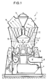
- the airflow grinding system 1 which is on a foundation, is usually enclosed in an airtight manner by a housing 2.
- the grinding plant consists of a lower roller mill, above which an integrated classifier 11 is installed in the upper area.
- the grinding bowl 3 is set in rotation via a drive 4.
- the regrind fed from above or from the side onto the grinding bowl 3 is comminuted between the resiliently pressed grinding rollers 9 and the grinding bowl 3.
- the grinding rollers 9 do not have a separate drive, but are set in rotation solely by the frictional connection between grinding bowl 3 or the grinding material present between them and the grinding bowl.
- the air flowing in via the feed channel 6 and the guide vane ring 16 conveys the mixture of finished and coarse material which is thrown off the grinding bowl 3 after being rolled over by the grinding rollers 9 Grain upwards in the area of the classifier 11. Due to the rotor 12, which is driven by its own rotor drive 14, oversize is rejected in accordance with the rotation and the rising volume flow of the air dust mixture 13, so that this, together with a partial air flow, is returned to the grinding bowl 3 in the area of a so-called vertebral sink 8 falls back. The fines or finished goods, on the other hand, leave the classifier 11 via the fines outlet 15.
- FIG. 1 These normally occurring flow conditions of the air / dust mixture are shown in FIG. 1 with broken lines as current threads.
- a vertebral sink 8 forms below the classifying rotor 12 in the center of the roller mill, wherein not only ground material particles, but also air or gas are almost returned downwards to the grinding bowl 3 in the circuit.
- This air / dust mixture is drawn in by the grinding rollers 3 and rolled over. The air naturally escapes.
- the oversize rejected by the classifier 11 is also much finer. Since the buoyancy of the finest semolina in the air is higher than in the case of coarse semolina, the proportion of gravity that returns the oversize particles to the grinding bowl 3 also becomes lower. Ultimately, this means that an extremely highly ventilated "dust cloud” falls back on the grinding bowl or is returned. This cloud of dust can be compared to a liquid from a physical point of view due to its very low internal friction.
- the invention is therefore based on the object of constructing a generic airflow grinding system in such a way that a high degree of efficiency with regard to the mill throughput is achieved, in particular when a high degree of fineness of the grinding material is required, where possible the functional sequence becomes more uniform, so that impact loads during power consumption or in mechanical terms are largely reduced.
- the grinding rollers are therefore forcibly driven by appropriately separately assigned drive devices, such as e.g. Electric motors driven at a speed that corresponds at least to the theoretical speed with a frictional connection between the grinding bowl and the corresponding grinding roller.
- This theoretical speed is understood to mean the speed that would occur if the grinding rollers were to rotate continuously as compared to a grinding bed existing in the prior art.
- the speed of the grinding rollers is advantageously chosen to be somewhat greater than the aforementioned theoretical speed. This ensures that there is no sliding or sliding or blocking of the grinding rollers with respect to the grinding bed or the grinding bowl, so that effective grinding of the material to be ground is actually achieved.
- This speed of the grinding rollers should, if possible, be infinitely adjustable so that an adjustment or regulation according to the fineness of the desired material to be ground, the size of the grinding bed, the load condition or the running behavior of the roller mill is possible.
- the forcibly applied speed of the grinding rollers, with which a dust wave forming in front of the roller can be prevented in any case, is therefore an essential feature of the invention.
- the drive torque T per grinding roller should be designed so that the drive torque T to be installed for a grinding roller is less than or equal to a value that results from the quotient of the torque of the grinding bowl T grinding bowl and the number of grinding rolls.
- the drive devices provided for the separate drive of the respective grinding roller are of any type, e.g. electrically, mechanically, hydraulically, expediently installed on the side remote from the grinding rollers.
- Drive devices such as electric motors, which can be uncoupled from the housing of the grinding system, are particularly suitable.
- the drive devices can also be stored and held separately from the housing. It is essential that the output shaft of the drive device can be decoupled from the drive shaft for the grinding rollers.
- the grinding roller is rotatably mounted in the rocker arm of the respective roller unit with a roller shaft rigidly attached to it.
- the drive device is then expediently attached to the rocker arm, so that rocking movements of the roller unit do not require separate compensation devices due to a different grinding bed height.
- the second alternative of the drive implementation provides for a stationary hollow axis arranged in the rocker arm.
- the grinding roller is also held in rotation at the inner end of the hollow axis via roller bearings, for example axial and radial bearings.
- the actual drive takes place via a drive shaft which is guided through the hollow axis and which applies the required torque to the grinding roller on the roller side via a closing device.
- This drive shaft is connected to the drive device at the other end, radial and axial adjustability, in particular gimbal type, of the entire shaft being possible via intermediate members.
- An electric motor provided, for example, as a drive device can in this case be fixed directly to the rocker arm or attached to the outside of the housing in such a way that it can be disconnected.
- a spring device which is at least in engagement with the rocking lever and is supported on a stationary part of the grinding system, is provided for applying the contact pressure of the roller against the ground material.
- the respective grinding roller is also driven according to the invention in addition to driving the grinding bowl 3.
- the corresponding speed and the torque are coordinated so that an independent rotation of the corresponding grinding roller occurs in front of the roller without the formation of a material material bow wave.
- the direction of rotation between the grinding roller and grinding bowl at the grinding gap or regrind bed is directed in the same direction.
- the exemplary embodiment according to FIG. 2 relates schematically to a first alternative for driving a grinding roller 20.
- the roller unit consisting of grinding roller 20 and rocking lever 25 is arranged so as to be pivotable about a rocker arm joint 34 on the housing or on its own foundation block on a bearing housing 35.
- the basic principle of this drive alternative is to provide a hollow shaft 23 rigidly fixed in the bushing 27 of the rocker arm 25, for example via a clamping device 36.
- the grinding roller is rotatably mounted on this hollow shaft 23 on the roll side, in FIG. 2 at the right end of the hollow shaft, via radial bearings 32 and angular bearings 33.
- the grinding roller 20, which in the example consists of the radially inner roller body 21 and the outer roller shell 22 forming a truncated cone, is driven with the appropriate torque via a drive shaft 24 which is guided in the hollow shaft 23 and is optionally supported.
- the roller shell 22 is fixed rigidly, but replaceably, on the roller body 21 via a bolt device 48 and a clamping ring 49.
- the roller unit shown in FIG. 2 is closed off by a cap-like closure device 44.
- This termination device 44 and its fastenings 50 serve primarily to transmit the drive torque from the inner drive shaft 24 via a coupling member 45 and its rigid connection 46 to the actual grinding roller.
- a dust-tight seal for the inner shafts and a counterbearing for the inclined bearing 33 is achieved by this termination device 44.
- the inner drive shaft 24 is connected via a coupling shaft 43 to the output shaft 42 of a schematically indicated motor 26, e.g. an electric motor, in connection.
- This motor 26 is held by a fastening 41 on an end plate 39 which is fixed on the rocker arm 25.
- the output shaft 42 of the motor 26 projects into the hollow axis 23 through a corresponding opening 40.
- the shaft members are designed so that there is an axial adjustment in the direction of the longitudinal axis of the hollow axis, but also a radial adjustment. Universal joints or universal joints are also possible as coupling links.
- roller unit is acted upon by a pressure spring 29 via a flange 28, this spring 29 being supported as a counter bearing in relation to a stationary part 30.
- both the grinding bowl 3 rotates about its axis of rotation 47 and - independently of it and designed with its own drive - the grinding roller unit, so that adverse effects, as set out above, are prevented by the separate drive of the grinding roller .
- the dimensioning of the bore 31 of the hollow shaft 23 is based on the outer circumference of the coupling members or the drive shaft 24 and on the other hand on the required stability for taking up the roll load and roll rotation.
- a roller shaft 56 connected to the grinding roller 55 is provided.
- This roller shaft is e.g. via bearings 53 rotatably mounted to absorb axial and radial forces in the bushing 52 of the rocker arm.
- the drive takes place here via a drive device 58 with a corresponding drive shaft 57.
- the rocker arm 25 is mounted in a manner similar to the aforementioned example via a rocker arm joint 34 relative to a bearing housing 35.
- the rocking lever 25 enables the compensating movements of the grinding roller 55 with respect to the grinding bowl 3 rotating about the axis 47.
- the rocking lever also serves to pivot the entire roller unit out of the corresponding housing of the grinding system.
- a pressure spring 29 supported on a stationary part 30 of the housing acts, as in the previous example, on the grinding roller 55 via a flange 28 and the rocker arm 25.
- the drive device 58 is fastened to the rocker arm 25 via a motor mount 54 in the example according to FIG. 3.
- the bearings of the roller shaft 56 are encapsulated, if possible, just like the actual drive device 58 in a dust-tight manner with respect to the interior 7 of the grinding system.
- the roller-side closure is formed by a rounded roller cap 69.
- FIGS. 2 and 3 could be used, for example, in a mill 1 according to FIG. 1 operated in a vacuum.
- FIG. 4 shows an airflow grinding system according to the invention in elevation, assemblies which largely correspond to the prior art being identified by the same reference numerals as in FIG. 1.
- the airflow grinding system 60 shown in FIG. 4 has a grinding bowl 61 in the area of the roller mill, which has a dome-like central elevation 62 for distributing the supplied or circulating material to be ground onto the grinding path.
- the millbase is supplied via a material feed channel 64 which runs centrally through the classifier 11 from top to bottom.
- a hollow rotor drive shaft 65 is rotatably provided around this channel for driving the rotor 12.
- the drive device of the grinding roller 20 shown on the left corresponds approximately to the alternative shown in FIG. 2, the torque being applied to the grinding roller 20 via a drive shaft 24 running in a hollow shaft.
- the drive shaft 42 protrudes through an opening 63 in the outer housing 2 of the grinding system.
- the passage openings or bearings for the drive shafts are designed to be gas and dust-tight, which is not reflected in the schematic drawing.
- the separate drive of the individual grinding rollers 20 prevents the material to be backed up in front of the rollers, thereby avoiding sliding or blocking effects which cause the roller mill to run unevenly and also bring about greater wear and tear.
- the drive units can be designed for a low maximum output, since impact stresses, as can still occur in the prior art, are largely prevented.
- the throughput performance even with a regrind with high required fineness can be significantly improved in this way.
Abstract
Description
Die Erfindung betrifft eine Luftstrom-Mahlanlage gemäß Oberbegriff des Anspruchs 1.The invention relates to an airflow grinding system according to the preamble of claim 1.
Eine derartige Luftstrom-Mahlanlage ist z.B. aus der DE-PS 20 19 005 bzw. der EP 0 173 065 A2 bekannt und in Fig. 1 dargestellt.Such an airflow grinding plant is e.g. known from DE-PS 20 19 005 and EP 0 173 065 A2 and shown in Fig. 1.
Zur Verdeutlichung der bei diesen herkömmlichen Luftstrom-Mahlanlagen bestehenden Probleme wird eine derartige Luftstrom-Mahlanlage 1 mit ihren wesentlichen Baugruppen und ihrer Funktionsweise nachfolgend kurz dargestellt.To clarify the problems existing in these conventional airflow grinding systems, such an airflow grinding system 1 with its essential assemblies and its mode of operation is briefly described below.
Die auf einem Fundament stehende Luftstrom-Mahlanlage 1 wird von einem Gehäuse 2 meist luftdicht umschlossen. Die Mahlanlage besteht aus einer unteren Wälzmühle, über der im oberen Bereich ein integrierter Sichter 11 installiert ist. Als einzige Baugruppe der Wälzmühle wird die Mahlschüssel 3 über einen Antrieb 4 in Rotation versetzt. Das von oben oder von der Seite auf die Mahlschüssel 3 zugeführte Mahlgut wird zwischen den federnd angepreßten Mahlwalzen 9 und der Mahlschüssel 3 zerkleinert. Die Mahlwalzen 9 haben hierbei keinen separaten Antrieb, sondern werden allein durch den Reibschluß zwischen Mahlschüssel 3 oder dem dazwischen vorhandenen Mahlgut und der Mahlschüssel in Drehung versetzt. Die über den Zufuhrkanal 6 und den Leitschaufelkranz 16 einströmende Luft fördert das von der Mahlschüssel 3 nach dem Überrollen durch die Mahlwalzen 9 abgeschleuderte Gutgemisch aus Fertig- und Grob korn nach oben in den Bereich des Sichters 11. Durch den über einen eigenen Rotorantrieb 14 angetriebenen Rotor 12 wird entsprechend der Rotation und dem aufsteigenden Volumenstrom des Luftstaubgemisches 13,Überkorn abgewiesen, so daß dieses zusammen mit einem Teilluftstrom wieder auf die Mahlschüssel 3 im Bereich einer sogenannten Wirbelsenke 8 zurückfällt. Das Feingut bzw. Fertiggut verläßt hingegen den Sichter 11 über den Feingut-Auslaß 15.The airflow grinding system 1, which is on a foundation, is usually enclosed in an airtight manner by a
Diese sich normalerweise einstellenden Strömungsverhältnisse des Luft-/Staubgemisches sind in Fig. 1 mit unterbrochenen Linien als Stromfäden dargestellt. Wie daraus erkennbar ist, bildet sich unterhalb des Sichterrotors 12 im Zentrum der Wälzenmühle eine Wirbelsenke 8, wobei hierin nicht nur Mahlgutpartikeln, sondern auch Luft bzw. Gas nahezu im Kreislauf nach unten auf die Mahlschüssel 3 zurückgeführt wird. Dieses Luft-/Staubgemisch wird von den Mahlwalzen 3 eingezogen und überrollt. Hierbei entweicht naturgemäß die Luft.These normally occurring flow conditions of the air / dust mixture are shown in FIG. 1 with broken lines as current threads. As can be seen from this, a vertebral sink 8 forms below the classifying
Verständlicherweise hängen diese sich einstellenden Strömungsverhältnisse im Innenraum 7 der Luftstrom-Mahlanlage 1 stark von der gewünschten Produktfeinheit ab. Bei Standard-Auslegungen derartiger Mahlanlagen, wie sie im Bereich der Zement-Rohmaterial-Kohlemahlung üblich sind, wird im Mittel ein Staub produziert, der eine Feinheit von ca. 10% bis 30% R DIN 0,09 besitzt.Understandably, these flow conditions in the
Sofern man mit der Luftstrom-Mahlanlage einen sehr viel feineren Staub als 10%R DIN 0,09 erzeugen will, wird das vom Sichter 11 abgewiesene Überkorn auch sehr viel feiner. Da der Auftrieb der Feinstgrieße in der Luft höher ist als bei Grobgrießen, wird demzufolge auch der Schwerkraftanteil, der das Überkorn auf die Mahlschüssel 3 zurückführt, geringer. Das bedeutet letztlich, daß eine extrem hoch belüftete "Staubwolke" auf die Mahlschüssel zurückfällt bzw. zurückgeführt ist. Diese Staubwolke kann aufgrund einer sehr geringen inneren Reibung in physikalischer Hinsicht nahezu mit einer Flüssigkeit verglichen werden.If you want to generate a much finer dust than 10% R DIN 0.09 with the airflow grinding system, the oversize rejected by the
Das Problem, das sich nunmehr bei derartigen herkömmlichen Luftstrom-Mahlanlagen einstellt, liegt darin, daß man ein stark belüftetes Mahlbett auf der Mahlschüssel 3 erhält, wobei dieses durch die Rotation der Mahlschüssel vor die Mahlwalzen 9 gefördert wird. Die Mahlwalzen 9 sind jedoch nur bedingt in der Lage, dieses stark belüftete Mahlbett einzuziehen. Hierdurch staut sich das stark belüftete Mahlgut zunächst vor den Mahlwalzen an, wobei die Luft aus dem Staub-/Luftgemisch verdrängt wird. Auf diese Weise bildet sich vor den Mahlwalzen eine kontinuierlich wachsende Staubwelle, die mit einer Bugwelle verglichen werden könnte.The problem that now arises in such conventional airflow grinding plants is that a strongly ventilated grinding bed is obtained on the
Nachdem in der bisherigen Bauart die Mahlwalzen 9 nur über die Reibung zwischen dem Mahlgut und der Mahlschüssel bzw. direkt mit dieser angetrieben werden, funktioniert der bisherige Reibkraftantrieb nicht oder nur sehr unvollkommen. Dies deshalb, da das Koppelmedium, das sich wie eine Staubwelle verhält, als stark belüftetes Mahlbett Eigenschaften wie eine Flüssigkeit aufweist. Die nachteilige Folge davon ist, daß die Mahlwalzen in ihrer Drehzahl abfallen oder sogar stehenbleiben.Since in the previous design the grinding rollers 9 were driven only via the friction between the material to be ground and the grinding bowl or directly with the latter, the previous friction force drive did not work or only worked incompletely. This is because the coupling medium, which behaves like a dust wave, has properties like a liquid as a strongly ventilated grinding bed. The disadvantageous consequence of this is that the grinding rollers drop in their speed or even stop.
Erst wenn genügend Luft aus dem Staub-/Luftgemisch des stark belüfteten Mahlbettes verdrängt ist, wird das Koppelmedium sozusagen ausreichend stabil, um die Mahlwalzen wieder über den Reibschluß anzutreiben und mitzunehmen. Da sich aber durch ein längeres Anstauen einer derart wachsenden Staubwelle schnell eine Art Keil aus Staub vor den Mahlwalzen aufbaut, stellt sich unvermeidlich der weitere Nachteil ein, das Mahlbett zügig und kontinuierlich unter die gefederten Mahlwalzen 9 zu ziehen. Die Mahlwalzen, die aufgrund dieser physikalischen Verhältnisse z.B. in ihrer Drehzahl abgefallen sind oder sogar stehenbleiben, werden nun ruckartig von dem angestauten Staubkeil angestoßen und müssen beschleunigt werden. Dies bedeutet jedoch, daß dann momentan ein sehr hoher Antriebsenergie-Bedarf besteht, da die Trägheit der großen Walzenmassen überwunden werden muß.Only when enough air is displaced from the dust / air mixture of the strongly ventilated grinding bed, the coupling medium becomes stable enough, so to speak, to drive the grinding rollers again via the frictional engagement and to take them along. However, since a kind of wedge of dust quickly builds up in front of the grinding rollers due to a prolonged accumulation of such a growing dust wave, the further disadvantage inevitably arises of pulling the grinding bed quickly and continuously under the spring-loaded grinding rollers 9. The grinding rollers, which have dropped or even stopped due to these physical conditions, for example, have now jerked off the jammed dust wedge and must be accelerated. However, this means that there is currently a very high demand for drive energy since the inertia of the large roll masses has to be overcome.
Die vorausgehend geschilderten Funktionsabläufe führen zu einem Slip-stick-Effekt an den Mahlwalzen, der sich in starken Mühlenvibrationen äußert. Abgesehen von mechanischen Schäden, die aufgrund dieses Gleit- und Blockiereffektes an der Luftstrom-Mahlanlage auftreten können, wird bei dieser diskontinuierlichen Arbeitsweise der Walzenmühlen auch der Mühlendurchsatz beeinträchtigt und reduziert.The above-described functional sequences lead to a slip-stick effect on the grinding rollers, which manifests itself in strong mill vibrations. Apart from mechanical damage that can occur on the airflow grinding system due to this sliding and blocking effect, the disc throughput of the roller mills also affects and reduces the mill throughput.
Ausgehend von den vorausgehend beim Stand der Technik vorliegenden Nachteilen liegt der Erfindung daher die Aufgabe zugrunde, eine gattungsgemäße Luftstrom-Mahlanlage konstruktiv so auszulegen, daß insbesondere bei einem geforderten hohen Feinheitsgrad des Mahlgutes ein hoher Wirkungsgrad im Hinblick auf den Mühlendurchsatz erreicht wird, wobei nach Möglichkeit eine Vergleichmäßigung des Funktionsablaufs eintritt, so daß Stoß-Beanspruchungen bei der Leistungsaufnahme oder in mechanischer Hinsicht weitgehend reduziert werden.Based on the disadvantages previously present in the prior art, the invention is therefore based on the object of constructing a generic airflow grinding system in such a way that a high degree of efficiency with regard to the mill throughput is achieved, in particular when a high degree of fineness of the grinding material is required, where possible the functional sequence becomes more uniform, so that impact loads during power consumption or in mechanical terms are largely reduced.
Diese Aufgabe wird erfindungsgemäß bei einer gattungsgemäßen Luftstrom-Mahlanlage durch die Merkmale des kennzeichnenden Teils des Anspruchs 1 gelöst.This object is achieved in a generic airflow grinding plant by the features of the characterizing part of claim 1.
Der Kerngedanke kann etwa darin gesehen werden, bei einer derartigen Mahlanlage von dem alleinigen Antrieb des Mahltellers abzugehen und stattdessen in Art einer Kombination dazu auch die einzelnen Mahlwalzen rotativ anzutreiben.The main idea can be seen, for example, in such a grinding system to depart from the sole drive of the grinding plate and instead to drive the individual grinding rollers in a manner of a combination in rotation.
Zwar erscheint dies auf den ersten Blick eine höhere Anlageninvestition zu bedingen, womit auch ein höherer Energiebedarf verbunden ist. In der Wirkungsweise führt die Erfindung letztlich dazu, daß durch eine kontinuierliche Arbeitsweise der Wälzmühle Stoßbeanspruchungen, die zu erhöhter mechanischer Abnutzung führen können, vermieden werden. Gleiches gilt auch für den Leistungsbedarf, der auf diese Weise vergleichmäßigt werden kann, womit auch die Auslegung dieser Aggregate nicht auf Spitzenbelastungen, wie sie bei Anlagen nach dem Stand der Technik auftreten konnten, ausgerichtet werden müssen.At first glance, this appears to necessitate a higher investment in the plant, which is also associated with a higher energy requirement. In effect, the invention ultimately leads to the fact that a continuous operation of the roller mill avoids impact loads which can lead to increased mechanical wear. The same applies to the power requirement, which can be equalized in this way, which means that the design of these units is not designed for peak loads, as is the case with systems could occur according to the state of the art, must be aligned.
Die Mahlwalzen werden daher zwangsweise über zweckmäßigerweise separat zugeordnete Antriebseinrichtungen, wie z.B. Elektromotoren mit einer Drehzahl angetrieben, die mindestens der theoretischen Drehzahl bei einem Reibschluß zwischen der Mahlschüssel und der entsprechenden Mahlwalze entspricht. Unter dieser theoretischen Drehzahl wird hierbei die Drehzahl verstanden, die bei einem kontinuierlichen Mitdrehen der Mahlwalzen gegenüber einem im Stand der Technik vorhandenen Mahlbett auftreten würde. Vorteilhafterweise wird die Drehzahl der Mahlwalzen etwas größer gewählt als die vorgenannte theoretische Drehzahl. Dies stellt sicher, daß kein Rutschen oder Gleiten oder Blockieren der Mahlwalzen gegenüber dem Mahlbett bzw. der Mahlschüssel auftritt, so daß auch tatsächlich ein effektives Zerkleinern des Mahlgutes realisiert wird.The grinding rollers are therefore forcibly driven by appropriately separately assigned drive devices, such as e.g. Electric motors driven at a speed that corresponds at least to the theoretical speed with a frictional connection between the grinding bowl and the corresponding grinding roller. This theoretical speed is understood to mean the speed that would occur if the grinding rollers were to rotate continuously as compared to a grinding bed existing in the prior art. The speed of the grinding rollers is advantageously chosen to be somewhat greater than the aforementioned theoretical speed. This ensures that there is no sliding or sliding or blocking of the grinding rollers with respect to the grinding bed or the grinding bowl, so that effective grinding of the material to be ground is actually achieved.
Diese Drehzahl der Mahlwalzen sollte nach Möglichkeit stufenlos einstellbar sein, so daß eine Anpassung oder Regelung nach der Feinheit des gewünschten Mahlgutes, nach der Mahlbettdicke, dem Lastzustand oder dem Laufverhalten der Wälzmühle möglich ist. Die zwangsweise aufgebrachte Drehzahl der Mahlwalzen, mit der auf alle Fälle eine sich vor der Walze bildende Staubwelle verhindert werden kann, ist daher ein wesentliches Merkmal der Erfindung.
Hinzu tritt, daß auch das Antriebsdrehmoment T pro Mahlwalze so ausgelegt werden sollte, daß das für eine Mahlwalze zu installierende Antriebsdrehmoment T kleiner oder gleich einem Wert ist, der sich aus dem Quotienten des Drehmomentes der Mahlschüssel TMahlschüssel und der Anzahl der Mahlwalzen ergibt.This speed of the grinding rollers should, if possible, be infinitely adjustable so that an adjustment or regulation according to the fineness of the desired material to be ground, the size of the grinding bed, the load condition or the running behavior of the roller mill is possible. The forcibly applied speed of the grinding rollers, with which a dust wave forming in front of the roller can be prevented in any case, is therefore an essential feature of the invention.
In addition, the drive torque T per grinding roller should be designed so that the drive torque T to be installed for a grinding roller is less than or equal to a value that results from the quotient of the torque of the grinding bowl T grinding bowl and the number of grinding rolls.
Unter Berücksichtigung dieser beiden Aspekte kann bei der Erfindung auf alle Fälle sichergestellt werden, daß der An trieb der Mahlwalzen rotativ so erfolgt, daß sozusagen ein Voreilen gegenüber einem reinen Reibantrieb, wie er bei Mahlanlagen im Stand der Technik vorhanden ist, erreicht wird.Taking these two aspects into account, it can be ensured in any case in the invention that the An drive the grinding rollers rotated so that, so to speak, an advance compared to a pure friction drive, as is present in grinding plants in the prior art, is achieved.
Da es sich bei derartigen Luftstrom-Mahlanlagen häufig um gasdichtgekapselte Anlagen handelt, in die auch die entsprechenden Mahlwalzen mit deren Schwinghebel integriert sind, sind die für den separaten Antrieb der jeweiligen Mahlwalze vorgesehenen Antriebseinrichtungen, die beliebiger Art sein können, z.B. elektrisch, mechanisch, hydraulisch, zweckmäßigerweise auf der den Mahlwalzen abgelegenen Seite installiert. Besonders geeignet sind Antriebseinrichtungen, wie Elektromotoren, die am Gehäuse der Mahlanlage abkoppelbar angebracht sind. Die Antriebseinrichtungen können auch separat zum Gehäuse gelagert und gehaltert werden. Wesentlich ist dabei, daß eine Entkopplung der Abtriebswelle der Antriebseinrichtung mit der Antriebswelle für die Mahlwalzen möglich ist.Since such airflow grinding systems are often gas-tight encapsulated systems, in which the corresponding grinding rollers with their rocker arms are also integrated, the drive devices provided for the separate drive of the respective grinding roller are of any type, e.g. electrically, mechanically, hydraulically, expediently installed on the side remote from the grinding rollers. Drive devices, such as electric motors, which can be uncoupled from the housing of the grinding system, are particularly suitable. The drive devices can also be stored and held separately from the housing. It is essential that the output shaft of the drive device can be decoupled from the drive shaft for the grinding rollers.
Für den separaten Antrieb der Mahlwalzen eignen sich zwei grundsätzliche Alternativen. Bei der ersten Alternative wird die Mahlwalze mit einer starr daran befestigten Walzenwelle rotativ im Schwinghebel der jeweiligen Walzeneinheit gelagert. Die Antriebseinrichtung ist dann zweckmäßigerweise am Schwinghebel befestigt, so daß Schwingbewegungen der Walzeneinheit aufgrund einer unterschiedlichen Mahlbetthöhe keine separaten Ausgleichseinrichtungen erfordern.
Die zweite Alternative der Antriebs-Realisierung sieht eine im Schwinghebel angeordnete stationäre Hohlachse vor. Auch die Mahlwalze ist dabei am inneren Ende der Hohlachse über Wälzlager, z.B. Axial- und Radiallager, rotativ gehalten. Der eigentliche Antrieb erfolgt über eine durch die Hohlachse geführte Antriebswelle, die walzenseitig über eine Abschlußeinrichtung das erforderliche Drehmoment auf die Mahlwalze aufbringt.There are two basic alternatives for the separate drive of the grinding rollers. In the first alternative, the grinding roller is rotatably mounted in the rocker arm of the respective roller unit with a roller shaft rigidly attached to it. The drive device is then expediently attached to the rocker arm, so that rocking movements of the roller unit do not require separate compensation devices due to a different grinding bed height.
The second alternative of the drive implementation provides for a stationary hollow axis arranged in the rocker arm. The grinding roller is also held in rotation at the inner end of the hollow axis via roller bearings, for example axial and radial bearings. The actual drive takes place via a drive shaft which is guided through the hollow axis and which applies the required torque to the grinding roller on the roller side via a closing device.
Diese Antriebswelle steht am anderen Ende mit der Antriebseinrichtung in Verbindung, wobei eine radiale und axiale Verstellbarkeit, insbesondere kardanischer Art, der gesamten Welle über Zwischenglieder möglich ist. Ein beispielsweise als Antriebseinrichtung vorgesehener Elektromotor kann hierbei direkt stationär am Schwinghebel befestigt sein oder abkoppelbar außen am Gehäuse angebracht sein.This drive shaft is connected to the drive device at the other end, radial and axial adjustability, in particular gimbal type, of the entire shaft being possible via intermediate members. An electric motor provided, for example, as a drive device can in this case be fixed directly to the rocker arm or attached to the outside of the housing in such a way that it can be disconnected.
In beiden alternativen Ausführungsformen ist eine mindestens mit dem Schwinghebel in Eingriff stehende Federeinrichtung, die an einem stationären Teil der Mahlanlage abgestützt ist, zur Aufbringung der Anpreßkraft der Walze gegen das Mahlgut vorgesehen.In both alternative embodiments, a spring device, which is at least in engagement with the rocking lever and is supported on a stationary part of the grinding system, is provided for applying the contact pressure of the roller against the ground material.
Anstelle der vorausgehend genannten Lagerung der entsprechenden Hohlwelle bzw. Walzenwelle in einem Schwinghebel kann auch eine direkte Lagerung im Gehäuse der Mahlanlage vorgesehen sein.Instead of the above-mentioned mounting of the corresponding hollow shaft or roller shaft in a rocker arm, a direct mounting in the housing of the grinding plant can also be provided.
Nachfolgend wird die Erfindung anhand zweier schematischer Ausführungsbeispiele noch näher erläutert. Es zeigen:
- Fig. 1 einen Aufriß durch eine Luftstrom-Mahlanlage gemäß Stand der Technik zur Verdeutlichung der Strömungsverhältnisse;
- Fig. 2 schematisch einen axialen Schnitt durch eine erste Alternative des Antriebs einer Mahlwalze, wobei die Walzeneinheit mit Schwinghebel dargestellt ist;
- Fig. 3 eine axiale Ansicht teilweise im Schnitt auf eine zweite Alternative des Antriebs für eine Mahlwalze und
- Fig. 4 einen Aufriß durch eine erfindungsgemäße Luftstrom-Mahlanlage, bei der einige Bezugszeichen und Baugruppen entsprechend der Fig. 1 beibehalten sind, jedoch mit einer Antriebsalternative, wie sie in etwa Fig. 2 entspricht.
- Figure 1 is an elevation through an airflow grinding system according to the prior art to illustrate the flow conditions.
- 2 schematically shows an axial section through a first alternative of driving a grinding roller, the roller unit being shown with a rocker arm;
- Fig. 3 is an axial view partly in section on a second alternative of the drive for a grinding roller and
- Fig. 4 is an elevation through an airflow grinding system according to the invention, in which some reference numerals and assemblies corresponding to FIG. 1 are retained, but with a drive alternative as it corresponds approximately to FIG. 2.
Die Luftstrom-Mahlanlage 1, wie sie in Fig. 1 im Aufriß dargestellt ist, wurde bereits in der Beschreibungseinleitung zur Veranschaulichung der auftretenden Nachteile und Probleme detailliert beschrieben. Da einzelne Baugruppen dieser Mahlanlage auch bei der Erfindung übereinstimmen, werden in der weiteren Erläuterung übereinstimmende Baugruppen auch mit gleichen Bezugszeichen gekennzeichnet.The airflow grinding system 1, as shown in elevation in FIG. 1, has already been described in detail in the introduction to the description to illustrate the disadvantages and problems that occur. Since individual assemblies of this grinding plant also match in the invention, matching assemblies are also identified with the same reference symbols in the further explanation.
Um daher bei Mahlanlagen nach dem Stand der Technik Nachteile wie den Slip-stick-Effekt oder Mühlenvibrationen zu vermeiden, wird erfindungsgemäß zusätzlich zum Antrieb der Mahlschüssel 3 auch die jeweilige Mahlwalze angetrieben. Die entsprechende Drehzahl und das Drehmoment sind dabei so abgestimmt, daß ein eigenständiges Drehen der entsprechenden Mahlwalze ohne die Bildung einer Materialgut-Bugwelle vor der Walze auftritt. Die Drehrichtung zwischen Mahlwalze und Mahlschüssel am Mahlspalt bzw. Mahlgutbett ist dabei gleichsinnig gerichtet.In order to avoid disadvantages such as the slip-stick effect or mill vibrations in grinding plants according to the prior art, the respective grinding roller is also driven according to the invention in addition to driving the grinding
Das Ausführungsbeispiel nach Fig. 2 betrifft schematisch eine erste Alternative des Antriebs einer Mahlwalze 20. Die aus Mahlwalze 20 und Schwinghebel 25 bestehende Walzeneinheit ist dabei stationär am Gehäuse oder auf einem eigenen Fundamentblock an einem Lagergehäuse 35 um ein Schwinghebel-Gelenk 34 schwenkbar angeordnet. Das Grundprinzip dieser Antriebsalternative besteht darin, in der Buchse 27 des Schwinghebels 25 eine Hohlachse 23 z.B. über eine Klemmvorrichtung 36 starr fixiert vorzusehen. Auf dieser Hohlachse 23 ist walzenseitig, in der Fig. 2 am rechten Ende der Hohlachse, über Radiallager 32 und Schräglager 33 die Mahlwalze rotativ gelagert. Die Mahlwalze 20, die im Beispiel aus dem radial inneren Walzenkörper 21 und dem äußeren, einen Kegelstumpf bildenden Walzenmantel 22 besteht, wird über eine in der Hohlachse 23 geführte und gegebenenfalls gelagerte Antriebswelle 24 mit dem entsprechenden Drehmoment angetrieben.The exemplary embodiment according to FIG. 2 relates schematically to a first alternative for driving a grinding
Der Walzenmantel 22 ist im Beispiel über eine Bolzeinrichtung 48 und einen Klemmring 49 starr, aber auswechselbar, auf dem Walzenkörper 21 befestigt. Auf der rechts liegenden Innenseite ist die in Fig. 2 dargestellte Walzeneinheit durch eine kappenartige Abschlußeinrichtung 44 abgeschlossen. Diese Abschlußeinrichtung 44 und deren Befestigungen 50 dienen primär zur Übertragung des Antriebsdrehmomentes von der inneren Antriebswelle 24 über ein Koppelglied 45 und dessen starre Verbindung 46 auf die eigentliche Mahlwalze. Gleichzeitig wird durch diese Abschlußeinrichtung 44 eine staubdichte Abdichtung für die Innenwellen und ein Gegenlager für das Schräglager 33 erreicht.In the example, the
Antriebsseitig steht die innere Antriebswelle 24 über eine Koppelwelle 43 mit der Abtriebswelle 42 eines schematisch angedeuteten Motors 26, z.B. eines Elektromotors, in Verbindung. Dieser Motor 26 ist über eine Befestigung 41 an einer Abschlußplatte 39, die am Schwinghebel 25 fixiert ist, gehaltert. Durch eine entsprechende Öffnung 40 ragt die Abtriebswelle 42 des Motors 26 in die Hohlachse 23 hinein. Die Wellenglieder sind so ausgelegt, daß eine axiale Anpassung in Richtung der Längsachse der Hohlachse, aber auch eine radiale Einstellmöglichkeit besteht. Auch Kreuzgelenke oder Kardangelenke sind als Koppelglieder möglich.On the drive side, the
Beispielhaft ist dargestellt, wie die Walzeneinheit über einen Flansch 28 durch eine Anpreßfeder 29 beaufschlagt wird, wobei diese Feder 29 gegenüber einem stationären Teil 30 als Gegenlager abgestützt ist.As an example, it is shown how the roller unit is acted upon by a
In der Ausführugnsform nach Fig. 2 dreht daher sowohl die Mahlschüssel 3 um deren Rotationsachse 47 als auch - unabhängig davon und mit eigenem Antrieb ausgelegt - die Mahlwalzeneinheit, so daß nachteilige Effekte, wie sie vorausgehend dargelegt sind, durch den separaten Antrieb der Mahlwalze verhindert werden.2 therefore both the grinding
Die Dimensionierung der Bohrung 31 der Hohlwelle 23 orientiert sich am Außenumfang der Koppelglieder bzw. der Antriebswelle 24 und andererseits an der erforderlichen Stabilität für die Aufnahme der Walzenlast und Walzendrehung.The dimensioning of the
In der zweiten Alternative des Antriebes einer Mahlwalze 55, wie sie schematisch und teilweise im Axialschnitt in Fig. 3 dargestellt ist, ist eine mit der Mahlwalze 55 verbundene Walzenwelle 56 vorgesehen. Diese Walzenwelle ist z.B. über Lager 53 zur Aufnahme axialer und radialer Kräfte in der Buchse 52 des Schwinghebels drehbar gelagert. Der Antrieb erfolgt hierbei über eine Antriebseinrichtung 58 mit entsprechender Antriebswelle 57. Der Schwinghebel 25 ist ähnlich wie im vorgenannten Beispiel über ein Schwinghebelgelenk 34 gegenüber einem Lagergehäuse 35 gelagert. Der Schwinghebel 25 ermöglicht die Ausgleichsbewegungen der Mahlwalze 55 gegenüber der um die Achse 47 rotierenden Mahlschüssel 3. Andererseits dient der Schwinghebel auch zum Ausschwenken der gesamten Walzeneinheit aus dem entsprechenden Gehäuse der Mahlanlage. Eine z.B. an einem stationären Teil 30 des Gehäuses abgestützte Anpreßfeder 29 wirkt ebenso wie im vorausgehenden Beispiel über einen Flansch 28 und den Schwinghebel 25 auf die Mahlwalze 55.In the second alternative of driving a grinding
Die Antriebseinrichtung 58 ist über eine Motorhalterung 54 im Beispiel nach Fig. 3 am Schwinghebel 25 befestigt. Die Lager der Walzenwelle 56 sind nach Möglichkeit ebenso wie die eigentliche Antriebseinrichtung 58 staubdicht gegenüber dem Innenraum 7 der Mahlanlage gekapselt. Der walzenseitige Abschluß ist im Ausführungsbeispiel durch eine gerundete Walzenkappe 69 gebildet.The
Die Antriebsalternativen nach den Figuren 2 und 3 könnten z.B. bei einer im Unterdruck betriebenen Mühle 1 nach der Figur 1 angewandt werden.The drive alternatives according to FIGS. 2 and 3 could be used, for example, in a mill 1 according to FIG. 1 operated in a vacuum.
Bei dieser Mühle 1 liegt der Schwinghebel 10 im wesentlichen außerhalb des Gehäuses 2, so daß eine direkte Befestigung der Antriebe 26 und 58, wie sie in den Figuren 2 und 3 bezüglich der Schwinghebel 25, 27 und 52 gezeigt sind, auch auf den Schwinghebeln 10 möglich wäre. Die Antriebe schwenken daher bei diesen Alternativen mit den entsprechenden Schwinghebeln z.B. um die Gelenkpunkte 34.
Die Fig. 4 zeigt eine Luftstrom-Mahlanlage gemäß der Erfindung im Aufriß, wobei Baugruppen, die weitgehend mit dem Stand der Technik übereinstimmen, mit gleichen Bezugszeichen wie nach Fig. 1 gekennzeichnet sind.
Die in Fig. 4 gezeichnete Luftstrom-Mahlanlage 60 weist im Wälzmühlenbereich eine Mahlschüssel 61 auf, die eine kuppelartige mittige Erhebung 62 zur Verteilung des zugeführten bzw. zirkulierenden Mahlgutes auf die Mahlbahn hat.
Die Mahlgutzufuhr erfolgt über einen zentral von oben nach unten durch den Sichter 11 hindurchgehenden Gutzufuhrkanal 64. Um diesen Kanal herum ist eine Rotor-Antriebshohlwelle 65 drehbar zum Antrieb des Rotors 12 vorgesehen.In this mill 1, the
FIG. 4 shows an airflow grinding system according to the invention in elevation, assemblies which largely correspond to the prior art being identified by the same reference numerals as in FIG. 1.
The
The millbase is supplied via a
Die Antriebseinrichtung der links dargestellten Mahlwalze 20 entspricht in etwa der nach Fig. 2 gezeigten Alternative, wobei das Drehmoment über eine in einer Hohlwelle laufenden Antriebswelle 24 auf die Mahlwalze 20 aufgebracht wird. Ein Motor 26, der über Befestigungsstreben 41 am Außengehäuse 2 gehaltert ist, treibt über die Antriebswelle 42 die Mahlwalze 20 separat an. Die Antriebswelle 42 ragt dabei durch eine Öffnung 63 im Außengehäuse 2 der Mahlanlage. Die Durchtrittsöffnungen bzw. auch Lagerungen für die Antriebswellen sind gas- und staubdicht ausgelegt, was in der schematischen zeichnerischen Darstellung nicht zum Ausdruck kommt.The drive device of the grinding
Da die Schwinghebel 25, 27 bei dieser Luftstrom-Mahlanlage 60 innerhalb des Gehäuses 2 angeordnet sind, verbietet sich eine direkte Befestigung des Antriebes 26 auf der Rückseite des Schwinghebels 27. Vielmehr muß der Antrieb 26 über die Halterung 41 nunmehr außen am Mühlengehäuse 2 befestigt sein. Die Schwenkbewegungen der Walzen 20 werden daher von den Antriebswellen 24 durch universelle Einstellbarkeit, die insbesondere durch Kardangelenkverbindungen realisiert sein kann, kompensiert.Since the
In der Gesamtfunktion vermeidet man durch den separaten Antrieb der einzelnen Mahlwalzen 20 ein Aufstauen des Mahlgutes vor den Walzen, wodurch Gleit- oder Blockierungseffekte, die ein unruhiges Laufen der Wälzmühle bewirken und auch höhere Abnutzungen mit sich bringen, vermieden werden. Die Antriebsaggregate können auf eine niedrige Maximalleistung ausgelegt werden, da Stoßbeanspruchungen, wie sie im Stand der Technik noch auftreten können, weitgehend verhindert werden. Die Durchsatzleistung auch bei einem Mahlgut bei hoher geforderter Feinheit kann auf diese Weise erheblich verbessert werden.In the overall function, the separate drive of the
Claims (10)
mit einer Wälzmühle, die mindestens eine stationär gelagerte Mahlwalze aufweist, die federnd gegen eine rotierend angetriebene Mahlschüssel anpreßbar ist bzw. sind,
mit einem über der Wälzmühle angeordneten, integrierten Sichter,
wobei das Mahlgut-Luft-Gemisch im wesentlichen vom Wälzmühlenzentrum her der Mahlschüssel und den Mahlwalzen zugeführt ist,
dadurch gekennzeichnet,
daß zusätzlich zur Mahlschüssel (3) auch die Mahlwalze (20;55) eine separate Antriebseinrichtung (26;58) aufweist, mittels der die Mahlwalze (20;55) zwangsweise rotativ mit einer Drehzahl gleichsinnig zur Mahlschüssel (3) antreibbar ist, die mindestens der theoretischen Drehzahl bei Reibschluß zwischen der Mahlschüssel (3) - mit oder ohne Mahlgut - und der Mahlwalze (20;55) entspricht, oder größer als diese theoretische Drehzahl ist.1. Airflow grinder
with a roller mill which has at least one stationary grinding roller which can be pressed against a rotatingly driven grinding bowl,
with an integrated sifter arranged above the roller mill,
the ground material-air mixture being fed to the grinding bowl and the grinding rollers essentially from the center of the roller mill,
characterized by
that in addition to the grinding bowl (3), the grinding roller (20; 55) has a separate drive device (26; 58), by means of which the grinding roller (20; 55) is forcibly rotatable in the same direction as the grinding bowl (3), which at least the theoretical speed with frictional engagement between the grinding bowl (3) - with or without regrind - and the grinding roller (20; 55) corresponds, or is greater than this theoretical speed.
dadurch gekennzeichnet,
daß auf jede Mahlwalze (20;55) ein Antriebsdrehmoment zwischen 0 und einem Wert TWalze aufgebracht ist, der durch die Gleichung

characterized by
that a drive torque between 0 and a value T roller is applied to each grinding roller (20; 55), which is determined by the equation
dadurch gekennzeichnet,
daß die Drehzahl der Mahlwalzen (20;55) einstellbar, insbesondere stufenlos einstellbar, ausgelegt ist.3. Airflow grinding plant according to claim 1 or 2,
characterized by
that the speed of the grinding rollers (20; 55) is adjustable, in particular continuously adjustable.
dadurch gekennzeichnet,
daß die Drehzahl der Mahlwalzen (20;55) abhängig von der Feinheit des Mahlgutes, der Mahlbettdicke, dem Lastzustand oder dem Laufverhalten der Wälzmühle einstellbar ist.4. Airflow grinding plant according to claim 3,
characterized by
that the speed of the grinding rollers (20; 55) is adjustable depending on the fineness of the material to be ground, the bed size, the load condition or the running behavior of the roller mill.
mit einer Wälzmühle, die mehrere stationär gelagerte Mahlwalzen aufweist, die federnd gegen eine rotierend angetriebene Mahlschüssel anpreßbar ist,
mit einem über der Wälzmühle angeordneten, integrierten Sichter, wobei das Mahlgut-Luft-Gemisch im wesentlichen vom Wälzmühlenzentrum her der Mahlschüssel und den Mahlwalzen zugeführt ist,
mit einer separaten Antriebseinrichtung, mit der die Mahlwalzen zwangsweise rotativ mit einer Drehzahl antreibbar sind,
dadurch gekennzeichnet
, daß die zwangsweise rotativ aufgebrachte Drehzahl jeder Mahlwalze (20;25) gleichsinnig zur Mahlschüssel (3) erfolgt und größer ist als die theoretische Drehzahl bei Reibschluß zwischen der Mahlgut aufweisenden Mahlschüssel (3) und der jeweiligen Mahlwalze (20;25), und
daß jede Mahlwalze (20) auf einer feststehenden Hohlachse (23) gelagert ist, in der eine Antriebswelle (24,42,43,45) für die Mahlwalze (20) angeordnet ist, wobei der Antrieb der Antriebswelle auf der der Mahlwalze (20) abgewandten Seite erfolgt.5. Airflow grinding plant, in particular according to one of claims 1 to 4,
with a roller mill which has a plurality of stationary grinding rollers which can be pressed resiliently against a rotatingly driven grinding bowl,
with an integrated classifier arranged above the roller mill, the ground material / air mixture being fed to the grinding bowl and the grinding rollers essentially from the center of the roller mill,
with a separate drive device with which the grinding rollers can forcibly be rotated at a speed,
characterized
that the forced rotational speed of each grinding roller (20; 25) takes place in the same direction as the grinding bowl (3) and is greater than the theoretical speed with frictional engagement between the grinding bowl (3) and the respective grinding roller (20; 25), and
that each grinding roller (20) is mounted on a fixed hollow shaft (23) in which a drive shaft (24, 42, 43, 45) for the grinding roller (20) is arranged, the drive of the drive shaft on that of the grinding roller (20) facing away.
dadurch gekennzeichnet,
daß die Antriebswelle (24,42,43,45) einstellbar, insbesondere in radialer und axialer Richtung, ausgelegt ist.6. Airflow grinding plant according to claim 5,
characterized by
that the drive shaft (24, 42, 43, 45) is adjustable, in particular in the radial and axial directions.
dadurch gekennzeichnet,
daß auf der zum Wälzmühlenzentrum (8) orientierten Seite der Hohlachse (23) eine Abschlußeinrichtung (44) zur Abdichtung der Hohlachse (23) gegenüber dem Innenraum (7) der Mahlanlage (60) und zur Drehmomentübertragung auf die Mahlwalzen (20) vorgesehen ist.7. Airflow grinding plant according to claim 5 or 6,
characterized by
that on the side of the roller mill center (8) oriented side of the hollow shaft (23) a closing device (44) for sealing the hollow shaft (23) against the interior (7) of the grinding system (60) and for torque transmission to the grinding rollers (20) is provided.
dadurch gekennzeichnet,
daß jede Mahlwalze (55) starr mit einer Walzenwelle (56) verbunden ist, die drehbar im Gehäuse (2) der Mahlanlage (60) oder einem der Mahlwalze (55) zugeordnetem Schwinghebel (25,52) gelagert ist, wobei die Walzenwelle (56) starr oder elastisch mit der Antriebseinrichtung (58) gekoppelt ist.8. Airflow grinding plant according to one of claims 1 to 4,
characterized by
that each grinding roller (55) is rigidly connected to a roller shaft (56) which is rotatably mounted in the housing (2) of the grinding system (60) or an oscillating lever (25, 52) assigned to the grinding roller (55), the roller shaft (56 ) is rigidly or elastically coupled to the drive device (58).
dadurch gekennzeichnet,
daß eine elektrische, mechanische oder hydraulische Antriebseinrichtung (26;58) vorgesehen ist.9. Airflow grinding plant according to one of claims 1 to 8,
characterized by
that an electrical, mechanical or hydraulic drive device (26; 58) is provided.
dadurch gekennzeichnet,
daß die Antriebseinrichtung (26;58) abkoppelbar am oder separat zum Gehäuse (2) der Mahlanlage (60) oder einem stationären Teil der Mahlanlage vorgesehen ist.10. Airflow grinding plant according to one of claims 1 to 9,
characterized by
that the drive device (26; 58) is provided on or separate from the housing (2) of the grinding system (60) or a stationary part of the grinding system.
Applications Claiming Priority (2)
| Application Number | Priority Date | Filing Date | Title |
|---|---|---|---|
| DE3815218 | 1988-05-04 | ||
| DE3815218A DE3815218A1 (en) | 1988-05-04 | 1988-05-04 | AIRFLOW MACHINE |
Publications (2)
| Publication Number | Publication Date |
|---|---|
| EP0340510A2 true EP0340510A2 (en) | 1989-11-08 |
| EP0340510A3 EP0340510A3 (en) | 1990-03-07 |
Family
ID=6353634
Family Applications (1)
| Application Number | Title | Priority Date | Filing Date |
|---|---|---|---|
| EP89106732A Withdrawn EP0340510A3 (en) | 1988-05-04 | 1989-04-14 | Airflow mill arrangement |
Country Status (5)
| Country | Link |
|---|---|
| EP (1) | EP0340510A3 (en) |
| JP (1) | JPH0710357B2 (en) |
| DE (1) | DE3815218A1 (en) |
| DK (1) | DK183189A (en) |
| ZA (1) | ZA893019B (en) |
Cited By (3)
| Publication number | Priority date | Publication date | Assignee | Title |
|---|---|---|---|---|
| DE3938320A1 (en) * | 1989-11-17 | 1991-05-23 | Krupp Polysius Ag | WAELZMUEHLE |
| DE102010056044A1 (en) * | 2010-12-23 | 2012-06-28 | Keller Hcw Gmbh | Runner jacket and rim for a Koller runner, Kollerläufer and method for producing the Kollerläufers |
| CN108698049A (en) * | 2016-02-08 | 2018-10-23 | 德国莱歇公司 | Grinding roller device |
Families Citing this family (10)
| Publication number | Priority date | Publication date | Assignee | Title |
|---|---|---|---|---|
| DE102007006092A1 (en) * | 2007-02-07 | 2008-08-14 | Polysius Ag | Process for comminuting regrind with a roller mill |
| DE102008036784C5 (en) * | 2008-08-07 | 2013-06-20 | Thyssenkrupp Polysius Ag | Roller mill and method for comminution of regrind |
| DE102008039539B4 (en) * | 2008-08-25 | 2010-08-26 | Polysius Ag | roller mill |
| DE102008039542B4 (en) * | 2008-08-25 | 2010-04-15 | Polysius Ag | roller mill |
| DE102008039543B4 (en) * | 2008-08-25 | 2010-05-12 | Polysius Ag | roller mill |
| DE102009012353C5 (en) * | 2009-03-09 | 2013-08-22 | ThyssenKrupp Resource Technologies AG | roller mill |
| CN103596692B (en) * | 2011-09-30 | 2015-09-23 | 三菱重工业株式会社 | Biomass powder crushing device and living beings/coal mixture burning control system |
| CN104329660A (en) * | 2011-09-30 | 2015-02-04 | 三菱重工业株式会社 | Biomass crushing device and biomass/coal co-combustion system |
| JP6469343B2 (en) * | 2013-12-13 | 2019-02-13 | 三菱日立パワーシステムズ株式会社 | Solid fuel pulverizer and method of manufacturing solid fuel pulverizer |
| JP6413025B2 (en) * | 2014-10-31 | 2018-10-24 | ロエシェ ゲーエムベーハー | Grinding roller |
Citations (1)
| Publication number | Priority date | Publication date | Assignee | Title |
|---|---|---|---|---|
| DE3602932A1 (en) * | 1986-01-31 | 1987-08-06 | Kloeckner Humboldt Deutz Ag | Method and apparatus for comminuting solids |
Family Cites Families (5)
| Publication number | Priority date | Publication date | Assignee | Title |
|---|---|---|---|---|
| DE636062C (en) * | 1933-05-03 | 1936-10-01 | Ernst Curt Loesche | Grinding process |
| JPS58159854A (en) * | 1982-03-16 | 1983-09-22 | 株式会社神戸製鋼所 | Method and device for driving roller of vertical roller mill |
| JPS60197248A (en) * | 1984-03-21 | 1985-10-05 | 川崎重工業株式会社 | Roller device for vertical type roller mill |
| JPS62109743U (en) * | 1985-12-27 | 1987-07-13 | ||
| JPS6452551U (en) * | 1987-09-28 | 1989-03-31 |
-
1988
- 1988-05-04 DE DE3815218A patent/DE3815218A1/en not_active Ceased
-
1989
- 1989-04-14 EP EP89106732A patent/EP0340510A3/en not_active Withdrawn
- 1989-04-14 DK DK183189A patent/DK183189A/en not_active Application Discontinuation
- 1989-04-25 ZA ZA893019A patent/ZA893019B/en unknown
- 1989-05-02 JP JP1113541A patent/JPH0710357B2/en not_active Expired - Fee Related
Patent Citations (1)
| Publication number | Priority date | Publication date | Assignee | Title |
|---|---|---|---|---|
| DE3602932A1 (en) * | 1986-01-31 | 1987-08-06 | Kloeckner Humboldt Deutz Ag | Method and apparatus for comminuting solids |
Cited By (4)
| Publication number | Priority date | Publication date | Assignee | Title |
|---|---|---|---|---|
| DE3938320A1 (en) * | 1989-11-17 | 1991-05-23 | Krupp Polysius Ag | WAELZMUEHLE |
| DE102010056044A1 (en) * | 2010-12-23 | 2012-06-28 | Keller Hcw Gmbh | Runner jacket and rim for a Koller runner, Kollerläufer and method for producing the Kollerläufers |
| CN108698049A (en) * | 2016-02-08 | 2018-10-23 | 德国莱歇公司 | Grinding roller device |
| CN108698049B (en) * | 2016-02-08 | 2020-09-22 | 德国莱歇公司 | Grinding roller device |
Also Published As
| Publication number | Publication date |
|---|---|
| DK183189A (en) | 1989-11-05 |
| JPH0263559A (en) | 1990-03-02 |
| ZA893019B (en) | 1989-12-27 |
| EP0340510A3 (en) | 1990-03-07 |
| DE3815218A1 (en) | 1989-11-16 |
| DK183189D0 (en) | 1989-04-14 |
| JPH0710357B2 (en) | 1995-02-08 |
Similar Documents
| Publication | Publication Date | Title |
|---|---|---|
| EP0357762B1 (en) | Process and device for guiding and separating grains | |
| EP0369149B1 (en) | Stirring ball mill | |
| EP0406644B1 (en) | Air current-roller mill | |
| EP0615483B1 (en) | Eccentric-disc grinder | |
| EP0340510A2 (en) | Airflow mill arrangement | |
| DE2616155A1 (en) | WET GRINDING DEVICE | |
| EP1239966A1 (en) | Mill classifier | |
| WO2016207039A1 (en) | Material-bed roller mill | |
| EP2482987B1 (en) | Method and device for comminuting ore | |
| DE19715210C2 (en) | Grinding gap adjustment | |
| EP0856357B1 (en) | Impact scrusher | |
| EP3573762B1 (en) | Stirring mill | |
| WO2019192901A1 (en) | Grinding installations having tube mills and screen drums which are separated from one another | |
| EP0294609A2 (en) | Roller mill | |
| DE60123416T2 (en) | refiner | |
| WO2010023183A1 (en) | Roller mill | |
| DE3602932A1 (en) | Method and apparatus for comminuting solids | |
| DE4140549A1 (en) | Roller mill for crushing hard brittle material - has main motor drive combined with hydraulic drive to give a wide speed range. | |
| DE3220092A1 (en) | DISPERSING DEVICE | |
| DE2547709A1 (en) | VERTICAL-AXIS RECIRCULATION WIND SENSOR | |
| DE175299C (en) | ||
| DE1214516B (en) | Agitator mill for continuous fine grinding and dispersing of solids | |
| DE903779C (en) | Plate crusher | |
| DE106932C (en) | ||
| EP0677329A1 (en) | Ring ball mill |
Legal Events
| Date | Code | Title | Description |
|---|---|---|---|
| PUAI | Public reference made under article 153(3) epc to a published international application that has entered the european phase |
Free format text: ORIGINAL CODE: 0009012 |
|
| AK | Designated contracting states |
Kind code of ref document: A2 Designated state(s): DE FR GB |
|
| PUAL | Search report despatched |
Free format text: ORIGINAL CODE: 0009013 |
|
| AK | Designated contracting states |
Kind code of ref document: A3 Designated state(s): DE FR GB |
|
| STAA | Information on the status of an ep patent application or granted ep patent |
Free format text: STATUS: THE APPLICATION IS DEEMED TO BE WITHDRAWN |
|
| 18D | Application deemed to be withdrawn |
Effective date: 19900908 |