EP0340463A1 - Faseroptische Leuchtzeichenanlage - Google Patents
Faseroptische Leuchtzeichenanlage Download PDFInfo
- Publication number
- EP0340463A1 EP0340463A1 EP89105928A EP89105928A EP0340463A1 EP 0340463 A1 EP0340463 A1 EP 0340463A1 EP 89105928 A EP89105928 A EP 89105928A EP 89105928 A EP89105928 A EP 89105928A EP 0340463 A1 EP0340463 A1 EP 0340463A1
- Authority
- EP
- European Patent Office
- Prior art keywords
- illuminated sign
- holes
- sign system
- light source
- luminous
- Prior art date
- Legal status (The legal status is an assumption and is not a legal conclusion. Google has not performed a legal analysis and makes no representation as to the accuracy of the status listed.)
- Withdrawn
Links
- 239000000835 fiber Substances 0.000 title claims abstract description 5
- 230000003287 optical effect Effects 0.000 claims abstract description 17
- 238000004519 manufacturing process Methods 0.000 claims abstract description 3
- 239000013307 optical fiber Substances 0.000 claims description 8
- 229920000515 polycarbonate Polymers 0.000 claims description 4
- 239000004417 polycarbonate Substances 0.000 claims description 4
- 229920006352 transparent thermoplastic Polymers 0.000 claims description 4
- 239000004811 fluoropolymer Substances 0.000 claims description 3
- 229920002313 fluoropolymer Polymers 0.000 claims description 3
- 229910052736 halogen Inorganic materials 0.000 claims description 2
- 150000002367 halogens Chemical class 0.000 claims description 2
- 125000005397 methacrylic acid ester group Chemical group 0.000 claims description 2
- 229920000642 polymer Polymers 0.000 claims description 2
- 239000012815 thermoplastic material Substances 0.000 claims description 2
- 229920001169 thermoplastic Polymers 0.000 abstract description 4
- 239000004416 thermosoftening plastic Substances 0.000 abstract description 4
- 238000009434 installation Methods 0.000 abstract description 2
- 229920003229 poly(methyl methacrylate) Polymers 0.000 description 4
- 239000004926 polymethyl methacrylate Substances 0.000 description 4
- 239000000853 adhesive Substances 0.000 description 2
- 230000001070 adhesive effect Effects 0.000 description 2
- 239000003086 colorant Substances 0.000 description 2
- -1 polyethylene Polymers 0.000 description 2
- 239000002033 PVDF binder Substances 0.000 description 1
- 239000004698 Polyethylene Substances 0.000 description 1
- 239000004743 Polypropylene Substances 0.000 description 1
- 239000004793 Polystyrene Substances 0.000 description 1
- 239000003822 epoxy resin Substances 0.000 description 1
- 230000004907 flux Effects 0.000 description 1
- 238000010438 heat treatment Methods 0.000 description 1
- 239000004922 lacquer Substances 0.000 description 1
- 239000002184 metal Substances 0.000 description 1
- 239000004033 plastic Substances 0.000 description 1
- 229920003023 plastic Polymers 0.000 description 1
- 239000013308 plastic optical fiber Substances 0.000 description 1
- 229920000647 polyepoxide Polymers 0.000 description 1
- 229920000573 polyethylene Polymers 0.000 description 1
- 229920001155 polypropylene Polymers 0.000 description 1
- 229920002223 polystyrene Polymers 0.000 description 1
- 229920000915 polyvinyl chloride Polymers 0.000 description 1
- 239000004800 polyvinyl chloride Substances 0.000 description 1
- 229920002981 polyvinylidene fluoride Polymers 0.000 description 1
- 230000005855 radiation Effects 0.000 description 1
Images
Classifications
-
- G—PHYSICS
- G08—SIGNALLING
- G08B—SIGNALLING OR CALLING SYSTEMS; ORDER TELEGRAPHS; ALARM SYSTEMS
- G08B1/00—Systems for signalling characterised solely by the form of transmission of the signal
-
- G—PHYSICS
- G09—EDUCATION; CRYPTOGRAPHY; DISPLAY; ADVERTISING; SEALS
- G09F—DISPLAYING; ADVERTISING; SIGNS; LABELS OR NAME-PLATES; SEALS
- G09F9/00—Indicating arrangements for variable information in which the information is built-up on a support by selection or combination of individual elements
- G09F9/30—Indicating arrangements for variable information in which the information is built-up on a support by selection or combination of individual elements in which the desired character or characters are formed by combining individual elements
- G09F9/305—Indicating arrangements for variable information in which the information is built-up on a support by selection or combination of individual elements in which the desired character or characters are formed by combining individual elements being the ends of optical fibres
-
- B—PERFORMING OPERATIONS; TRANSPORTING
- B60—VEHICLES IN GENERAL
- B60Q—ARRANGEMENT OF SIGNALLING OR LIGHTING DEVICES, THE MOUNTING OR SUPPORTING THEREOF OR CIRCUITS THEREFOR, FOR VEHICLES IN GENERAL
- B60Q1/00—Arrangement of optical signalling or lighting devices, the mounting or supporting thereof or circuits therefor
- B60Q1/0011—Arrangement of optical signalling or lighting devices, the mounting or supporting thereof or circuits therefor with light guides for distributing the light between several lighting or signalling devices
-
- G—PHYSICS
- G02—OPTICS
- G02B—OPTICAL ELEMENTS, SYSTEMS OR APPARATUS
- G02B6/00—Light guides; Structural details of arrangements comprising light guides and other optical elements, e.g. couplings
- G02B6/0001—Light guides; Structural details of arrangements comprising light guides and other optical elements, e.g. couplings specially adapted for lighting devices or systems
- G02B6/0005—Light guides; Structural details of arrangements comprising light guides and other optical elements, e.g. couplings specially adapted for lighting devices or systems the light guides being of the fibre type
-
- G—PHYSICS
- G09—EDUCATION; CRYPTOGRAPHY; DISPLAY; ADVERTISING; SEALS
- G09F—DISPLAYING; ADVERTISING; SIGNS; LABELS OR NAME-PLATES; SEALS
- G09F13/00—Illuminated signs; Luminous advertising
- G09F13/04—Signs, boards or panels, illuminated from behind the insignia
- G09F13/0418—Constructional details
- G09F13/0472—Traffic signs
Definitions
- the invention relates to a luminous sign system, consisting essentially of a luminous element, a light source and a system of optical fibers, which connects the luminous element to the light source.
- Luminous bodies and optical fibers are made of a thermoplastic.
- a light guide system for e.g. Motor vehicle tail lamp groups for the generation of simultaneous light signals with different durations and colors and at different times in separate luminaries e.g. DE-OS 33 19 179.
- the luminous elements are connected to a common central light source in a distributor housing with the aid of light guides. However, the luminous elements still require additional devices for distributing the light arriving through the light guides in the luminous element.
- a fiber optic variable message sign based on a micro grid system is also known (cf. SCHOTTinformation 3/1987, pp. 14-17).
- the luminous element is connected to light sources by means of light guides, which are switched on as required.
- Each of the many light points in the luminous body is equipped with special optics, which makes the traffic sign very complex and expensive.
- the task was to find a sign system that is easy and inexpensive to manufacture.
- the object can be achieved if the luminous element is a plate-shaped structure made of thermoplastic material and has a large number of holes, and the optical waveguides end directly in the holes.
- the invention thus relates to the fiber optic illuminated sign system and its use.
- the illuminated sign system essentially consists of a luminous element, a light source and a system of optical waveguides, which connects the luminous element to the light source.
- the luminous body is a plate-shaped structure.
- the thickness of the filament is 1 to 10, preferably 2 to 5 mm.
- the luminous element is provided with a multiplicity of holes which preferably have a circular cross section with a diameter of 0.2 to 1.5, preferably 0.25 to 0.75 mm and are preferably arranged in patterns.
- the distance between the holes is 2 to 10, preferably 2 to 6 mm.
- the luminous element is connected to a light source by means of an optical waveguide system comprising at least one bundle of fibrous optical waveguides made of a transparent thermoplastic.
- the cross section of the individual optical fibers corresponds to the cross section of the aforementioned holes.
- the optical waveguides end in the holes, preferably they end flush on the front of the filament.
- the filament consists of a thermoplastic.
- Polymethyl methacrylate, polycarbonate, polystyrene, polyethylene, polypropylene, PVC are suitable as such.
- Polymethyl methacrylate and polycarbonate are preferred.
- thermoplastic is transparent
- the rear side facing the optical waveguides can be colored.
- front side facing away from the optical waveguides can be roughened.
- the transparent thermoplastic plastic of the optical waveguide consists essentially of a polycarbonate, a methacrylic acid ester polymer or a fluoropolymer.
- the light source of the illuminated sign system according to the invention can be of various types, provided that it offers a sufficient luminous flux, preferably a halogen lamp is used.
- Colored filters can be arranged between the light source and the optical waveguide system, in order to produce luminous characters of different colors in the luminous element. It is also possible to bundle the optical waveguides according to certain patterns and to bring the bundles to different light sources.
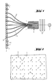
- (1) means the luminous element with the front (2) and back (3), (5) a bundle of the optical waveguides (4), (6) color filters and (7) the light source.
- core polymethyl methacrylate, jacket fluoropolymer diameter 0.5 mm; length 1.5 m
- optical fibers of each band were combined separately and fused together with the aid of a shrink tube based on polyvinylidene fluoride and heating to a temperature of 180 ° C. to form a light guide rod with a diameter of 10 mm.
- the ends of the light guide rods were polished and encased in metal sleeves. Color filters and a light source were installed in front of the polished ends of the light guide rods.
- This illuminated sign system could be used as a motor vehicle rear light.
Landscapes
- Physics & Mathematics (AREA)
- General Physics & Mathematics (AREA)
- Engineering & Computer Science (AREA)
- Theoretical Computer Science (AREA)
- Mechanical Engineering (AREA)
- Optics & Photonics (AREA)
- Illuminated Signs And Luminous Advertising (AREA)
- Non-Portable Lighting Devices Or Systems Thereof (AREA)
- Road Signs Or Road Markings (AREA)
- Optical Fibers, Optical Fiber Cores, And Optical Fiber Bundles (AREA)
- Optical Couplings Of Light Guides (AREA)
- Lighting Device Outwards From Vehicle And Optical Signal (AREA)
- Artificial Filaments (AREA)
Abstract
Die erfindungsgemäße Leuchtzeichenanlage besteht im wesentlichen aus einem Leuchtkörper, einer Lichtquelle und einem System von Lichtwellenleitern, das Leuchtkörper und Lichtquelle verbindet. Der Leuchtkörper ist ein mit einer Vielzahl von Löchern versehenes plattenförmiges Gebilde aus thermoplastischem Kunststoff und die Lichtwellenleiter enden in den Löchern direkt. Die Leuchtzeichenanlage ist einfach zu fertigen und zeichnet sich durch eine geringe Einbautiefe aus. Sie ist insbesondere als Kraftfahrzeug-Rückleuchte verwendbar.
Description
- Die Erfindung bezieht sich auf eine Leuchtzeichenanlage, bestehend im wesentlichen aus einem Leuchtkörper, einer Lichtquelle und einem System von Lichtwellenleitern, das den Leuchtkörper mit der Lichtquelle verbindet. Leuchtkörper und Lichtwellenleiter bestehen aus einem thermoplastischen Kunststoff.
- Bekannt ist ein Lichtleitersystem für z.B. Kraftfahrzeugrückleuchtengruppen zur Erzeugung von gleichzeitigen Lichtsignalen mit unterschiedlicher Dauer und Farbe und zu unterschiedlichen Zeiten in voneinander getrennten Leuchtkörpern (vgl. DE-OS 33 19 179). Die Leuchtkörper sind mit Hilfe von Lichtleitern mit einer gemeinsamen zentralen Lichtquelle in einem Verteilergehäuse verbunden. Allerdings benötigen die Leuchtkörper noch zusätzliche Einrichtungen zum Verteilen des durch die Lichtleiter ankommenden Lichtes im Leuchtkörper.
- Weiterhin ist ein faseroptisches Wechselverkehrszeichen nach einem Mikroraster-System bekannt (vgl. SCHOTTinformation 3/1987, S. 14-17). Der Leuchtkörper ist mittels Lichtleitern mit Lichtquellen verbunden, welche nach Bedarf eingeschaltet werden. Jeder der vielen Lichtpunkte im Leuchtkörper ist mit einer speziellen Optik ausgestattet, wodurch das Verkehrszeichen sehr aufwendig und teuer wird.
- Die Aufgabe bestand darin, eine Leuchtzeichenanlage zu finden, welche einfach und preiswert zu fertigen ist.
- Es wurde gefunden, daß die Aufgabe gelöst werden kann, wenn der Leuchtkörper ein mit einer Vielzahl von Löchern versehenes plattenförmiges Gebilde aus thermoplastischem Kunststoff ist und die Lichtwellenleiter in den Löchern direkt enden.
- Die Erfindung betrifft somit die in den Ansprüchen beschriebene faseroptische Leuchtzeichenanlage und ihre Verwendung.
- Die erfindungsgemäße Leuchtzeichenanlage besteht im wesentlichen aus einem Leuchtkörper, einer Lichtquelle und einem System von Lichtwellenleitern, das den Leuchtkörper mit der Lichtquelle verbindet.
- Der Leuchtkörper ist ein plattenförmiges Gebilde. Die Dicke des Leuchtkörpers beträgt 1 bis 10, vorzugsweise 2 bis 5 mm. Der Leuchtkörper ist mit einer Vielzahl von Löchern versehen, welche vorzugsweise einen kreisförmigen Querschnitt mit einem Durchmesser von 0,2 bis 1,5, vorzugsweise 0,25 bis 0,75 mm aufweisen und vorzugsweise in Mustern angeordnet sind. Der Abstand der Löcher voneinander beträgt 2 bis 10, vorzugsweise 2 bis 6 mm.
- Mit der Rückseite ist der Leuchtkörper mittels eines Lichtwellenleiter-Systems aus mindestens einem Bündel von faserförmigen Lichtwellenleitern aus einem transparenten thermoplastischem Kunststoff mit einer Lichtquelle verbunden. Der Querschnitt der einzelnen Lichtwellenleiter entspricht dem Querschnitt der vorgenannten Löcher. Die Lichtwellenleiter enden in den Löchern, vorzugsweise enden sie bündig an der Vorderseite des Leuchtkörpers.
- Der Leuchtkörper besteht aus einem thermoplastischem Kunststoff. Als solcher kommt infrage Polymethylmethacrylat, Polycarbonat, Polystyrol, Polyethylen, Polypropylen, PVC. Bevorzugt werden Polymethylmethacrylat und Polycarbonat.
- Wenn der thermoplastische Kunststoff transparent ist, kann die den Lichtwellenleitern zugewandte Rückseite farbig ausgestaltet sein. Um die Abstrahlcharakteristik des Leuchtkörpers zu verändern, kann die von den Lichtwellenleitern abgewandte Vorderseite aufgerauht sein. Der transparente thermoplastische Kunststoff der Lichtwellenleiter besteht im wesentlichen aus einem Polycarbonat, einem Methacrylsäureester-Polymer oder einem Fluorpolymer.
- Die Lichtquelle der erfindungsgemäßen Leuchtzeichenanlage kann verschiedener Art sein, sofern sie einen ausreichenden Lichtstrom bietet, vorzugsweise wird eine Halogenlampe eingesetzt. Zwischen der Lichtquelle und dem Lichtwellenleiter-System können farbige Filter angeordnet sein, um im Leuchtkörper Leuchtzeichen verschiedener Farbe zu erzeugen. Auch ist es möglich, die Lichtwellenleiter nach bestimmten Mustern zu bündeln und die Bündel an verschiedene Lichtquellen heranzuführen.
- Die erfindungsgemäße Leuchtzeichenanlage zeichnet sich durch eine geringe Einbautiefe aus.
- Figur 1 zeigt schematisch eine Leuchtzeichenanlage im Längsschnitt,
- Figur 2 eine Draufsicht auf die von den Lichtwellenleitern abgewandte Vorderseite des Leuchtkörpers.
- In den Figuren bedeuten (1) den Leuchtkörper mit Vorderseite (2) und Rückseite (3), (5) ein Bündel der Lichtwellenleiter (4), (6) Farbfilter und (7) die Lichtquelle.
- Das nachfolgende Beispiel soll die Erfindung erläutern.
- Eine 2 mm starke Platte aus farblosem Polymethylmethacrylat von der Größe 30 x 14,5 cm wurde auf der einen Seite mit einem silbergrauen Lack überzogen. Sodann wurden 1200 Löcher mit einem Durchmesser von 0,5 mm in 3 Bändern zu je 400 Löchern gebohrt. Die Bänder waren in Längsrichtung angeordnet, der Lochabstand innerhalb der Bänder betrug 5 mm. In die Löcher wurden Polymer-Lichtwellenleiter ( Kern Polymethylmethacrylat, Mantel Fluorpolymer; Durchmesser 0,5 mm; Länge 1,5 m) mittels eines Epoxyharzklebers so eingeklebt, daß die lackierte Fläche des Leuchtkörpers den Lichtwellenleitern zugewandt war. Nach dem Trocknen des Klebers wurde die von den Lichtwellenleitern abgewandte Vorderfläche des Leuchtkörpers poliert.
- Die Lichtwellenleiter eines jeden Bandes wurden gesondert zusammengefaßt und unter Zuhilfenahme eines Schrumpfschlauches auf Basis Polyvinylidenfluorid und Erhitzen auf eine Temperatur von 180°C zu je einem Lichtleitstab mit einem Durchmesser von 10 mm verschmolzen. Die Enden der Lichtleitstäbe wurden poliert und in Metallhülsen gefaßt. Vor die polierten Enden der Lichtleitstäbe wurden Farbfilter und eine Lichtquelle angebracht.
- Diese Leuchtzeichenanlage war als Kraftfahrzeug-Rückleuchte verwendbar.
Claims (10)
1. Faseroptische Leuchtzeichenanlage, im wesentlichen bestehend aus einem Leuchtkörper, einer Lichtquelle und einem System von Lichtwellenleitern, das den Leuchtkörper mit der Lichtquelle verbindet, dadurch gekennzeichnet, daß der Leuchtkörper ein mit einer Vielzahl von Löchern versehenes, plattenförmiges Gebilde aus einem thermoplastischen Kunststoff ist und das Lichtwellenleiter-System aus mindestens einem Bündel von faserförmigen Lichtwellenleitern aus einem transparenten thermoplastischen Kunststoff besteht, deren Querschnitt dem Querschnitt der genannten Löcher entspricht und die in diesen Löchern enden.
2. Leuchtzeichenanlage nach Anspruch 1, dadurch gekennzeichnet, daß die Dicke des Leuchtkörpers 1 bis 10 mm beträgt.
3. Leuchtzeichenanlage nach Anspruch 1, dadurch gekennzeichnet, daß die Löcher des Leuchtkörpers in Mustern angeordnet sind.
4. Leuchtzeichenanlage nach Anspruch 1, dadurch gekennzeichnet, daß die Löcher und die Lichtwellenleiter einen kreisförmigen Querschnitt aufweisen.
5. Leuchtzeichenanlage nach Anspruch 4, dadurch gekennzeichnet, daß der Querschnitt einen Durchmesser von 0,2 bis 1,5 mm aufweist.
6. Leuchtzeichenanlage nach Anspruch 1, dadurch gekennzeichnet, daß der Abstand der Löcher des Leuchtkörpers voneinander 2 bis 10 mm beträgt.
7. Leuchtzeichenanlage nach Anspruch 1, dadurch gekennzeichnet, daß die Lichtquelle eine Halogenlampe ist.
8. Leuchtzeichenanlage nach Anspruch 1, dadurch gekennzeichnet, daß zwischen der Lichtquelle und dem Lichtwellenleiter-System farbige Filter angeordnet sind.
9. Leuchtzeichenanlage nach Anspruch 1, dadurch gekennzeichnet, daß der transparente thermoplastische Kunststoff im wesentlichen aus einem Polycarbonat, Methacrylsäureester-Polymer oder Fluorpolymer besteht.
10. Verwendung der Leuchtzeichenanlage zur Herstellung von Kraftfahrzeug-Rückleuchten.
Applications Claiming Priority (2)
| Application Number | Priority Date | Filing Date | Title |
|---|---|---|---|
| DE3812418 | 1988-04-14 | ||
| DE3812418A DE3812418A1 (de) | 1988-04-14 | 1988-04-14 | Faseroptische leuchtzeichenanlage |
Publications (1)
| Publication Number | Publication Date |
|---|---|
| EP0340463A1 true EP0340463A1 (de) | 1989-11-08 |
Family
ID=6351968
Family Applications (1)
| Application Number | Title | Priority Date | Filing Date |
|---|---|---|---|
| EP89105928A Withdrawn EP0340463A1 (de) | 1988-04-14 | 1989-04-05 | Faseroptische Leuchtzeichenanlage |
Country Status (6)
| Country | Link |
|---|---|
| EP (1) | EP0340463A1 (de) |
| JP (1) | JPH01312588A (de) |
| KR (1) | KR900016925A (de) |
| CN (1) | CN1037986A (de) |
| AU (1) | AU3274589A (de) |
| DE (1) | DE3812418A1 (de) |
Cited By (2)
| Publication number | Priority date | Publication date | Assignee | Title |
|---|---|---|---|---|
| AT496U1 (de) * | 1993-11-26 | 1995-11-27 | Forster Franz Ing Gmbh | Faseroptisches leuchtzeichen |
| WO2001019643A1 (en) * | 1999-09-17 | 2001-03-22 | Lockheed Martin Corporation | Method and system for providing a reliable and durable light source |
Families Citing this family (6)
| Publication number | Priority date | Publication date | Assignee | Title |
|---|---|---|---|---|
| FR2653926B1 (fr) * | 1989-10-26 | 1994-04-29 | Commissariat Energie Atomique | Procede de fabrication d'un module agrandisseur d'images pour panneaux lumineux a fibres optiques. |
| JPH04889A (ja) * | 1990-04-17 | 1992-01-06 | Asahi Optical Co Ltd | オートホワイトバランスセンサの光入射装置 |
| DE4022649C1 (de) * | 1990-07-17 | 1991-10-24 | Dambach-Werke Gmbh, 7560 Gaggenau, De | |
| US5351065A (en) * | 1990-07-17 | 1994-09-27 | Dambach-Werke Gmbh | Indicator device |
| DE4212125C1 (de) * | 1992-04-13 | 1993-04-01 | Dambach-Werke Gmbh, 7554 Kuppenheim, De | |
| US7257914B2 (en) * | 2004-10-12 | 2007-08-21 | Hitachi Koki Usa Ltd. | Display system |
Citations (5)
| Publication number | Priority date | Publication date | Assignee | Title |
|---|---|---|---|---|
| GB1507883A (en) * | 1976-04-21 | 1978-04-19 | Barr & Stroud Ltd | Fibre optic display |
| GB2016132A (en) * | 1978-03-09 | 1979-09-19 | Zeiss Stiftung | Filter combination for fibre optic systems |
| FR2439938A1 (fr) * | 1978-10-25 | 1980-05-23 | Rouault Serge | Dispositif lumineux a guides de lumiere, economiseur d'energie |
| US4261936A (en) * | 1978-12-15 | 1981-04-14 | E. I. Du Pont De Nemours And Company | Jacketed optical filamentary material with thermoplastic core |
| JPS59212804A (ja) * | 1983-05-18 | 1984-12-01 | Sumitomo Electric Ind Ltd | プラスチツク光フアイバ− |
-
1988
- 1988-04-14 DE DE3812418A patent/DE3812418A1/de not_active Withdrawn
-
1989
- 1989-04-05 EP EP89105928A patent/EP0340463A1/de not_active Withdrawn
- 1989-04-13 KR KR1019890004876A patent/KR900016925A/ko not_active Withdrawn
- 1989-04-13 AU AU32745/89A patent/AU3274589A/en not_active Abandoned
- 1989-04-13 JP JP1092024A patent/JPH01312588A/ja active Pending
- 1989-04-13 CN CN89102266A patent/CN1037986A/zh active Pending
Patent Citations (5)
| Publication number | Priority date | Publication date | Assignee | Title |
|---|---|---|---|---|
| GB1507883A (en) * | 1976-04-21 | 1978-04-19 | Barr & Stroud Ltd | Fibre optic display |
| GB2016132A (en) * | 1978-03-09 | 1979-09-19 | Zeiss Stiftung | Filter combination for fibre optic systems |
| FR2439938A1 (fr) * | 1978-10-25 | 1980-05-23 | Rouault Serge | Dispositif lumineux a guides de lumiere, economiseur d'energie |
| US4261936A (en) * | 1978-12-15 | 1981-04-14 | E. I. Du Pont De Nemours And Company | Jacketed optical filamentary material with thermoplastic core |
| JPS59212804A (ja) * | 1983-05-18 | 1984-12-01 | Sumitomo Electric Ind Ltd | プラスチツク光フアイバ− |
Cited By (3)
| Publication number | Priority date | Publication date | Assignee | Title |
|---|---|---|---|---|
| AT496U1 (de) * | 1993-11-26 | 1995-11-27 | Forster Franz Ing Gmbh | Faseroptisches leuchtzeichen |
| WO2001019643A1 (en) * | 1999-09-17 | 2001-03-22 | Lockheed Martin Corporation | Method and system for providing a reliable and durable light source |
| US6439751B1 (en) | 1999-09-17 | 2002-08-27 | Lockheed Martin Corporation | Method and system for providing a reliable and durable light source |
Also Published As
| Publication number | Publication date |
|---|---|
| AU3274589A (en) | 1989-10-19 |
| DE3812418A1 (de) | 1989-10-26 |
| JPH01312588A (ja) | 1989-12-18 |
| CN1037986A (zh) | 1989-12-13 |
| KR900016925A (ko) | 1990-11-14 |
Similar Documents
| Publication | Publication Date | Title |
|---|---|---|
| DE2424041C2 (de) | Faseroptisches Band und Verfahren zu seiner Herstellung | |
| DE69208159T2 (de) | Verbesserte Platte zum rückseitigen Ausleuchten durch optische Fasern und Punkt-Verfahren zu ihrer Herstellung | |
| DE3101378C2 (de) | Optik zur Ankopplung eines faseroptischen Lichtwellenleiters | |
| EP0560043A2 (de) | Verfahren zum Herstellen von Bauelementen für Lichtwellenleiternetze und nach diesem Verfahren hergestellte Bauelemente | |
| DE2630632A1 (de) | Verfahren zur herstellung einer lichtleitenden glasfaser | |
| DE2914262A1 (de) | Optisches daempfungsglied fuer lichtleitfasern | |
| DE2749747A1 (de) | Strassenmarkierungsmaterial | |
| EP0340463A1 (de) | Faseroptische Leuchtzeichenanlage | |
| WO1998017889A1 (de) | Lichtleitplatten | |
| EP0495241A2 (de) | Lichtwellen-Bändchenkabel sowie Verfahren und Vorrichtung zur Herstellung des Bändchenkabels | |
| DE3780802T2 (de) | Einrichtung mit einer planaren optischen schaltung und daran gekoppelte optische faser. | |
| DE8804929U1 (de) | Kraftfahrzeug-Rückleuchte | |
| EP0376379A2 (de) | Verfahren zur Herstellung einer optischen Leitung | |
| DE19946079B4 (de) | Signalleuchte eines Kraftfahrzeugs | |
| DE3422972C2 (de) | Vorrichtung zum Positionieren und Fixieren von Lichtleitfasern in einer parallelen Anordnung zu einem Lichtleitfaserarray | |
| EP0315270A3 (de) | Optisches Mehrtorelement mit einem akustooptischen Modulator | |
| DE69305697T2 (de) | Optisches Bauelement gekoppelt an eine lineare Anordnung von optischen Fasern | |
| DE3500123C2 (de) | ||
| DE4407498A1 (de) | Aktivierung eines optischen Wellenleiters | |
| DE3919263A1 (de) | Verfahren und vorrichtung zur herstellung eines sternkopplers aus polymer-lichtwellenleitern | |
| EP0363853B1 (de) | Verfahren zur Herstellung eines faseroptischen Sternkopplers und nach diesem Verfahren hergestellter faseroptischer Sternkoppler | |
| DE3509053C1 (de) | Dreiweg-Sternteiler fuer Lichtwellenleiter | |
| DE3429626A1 (de) | Vorrichtung zum verbinden von lichtwellenleitern sowie eine damit hergestellte verbindung | |
| DE4214039C2 (de) | Vorrichtung zum Aufteilen von Lichtwellenleitern eines optischen Kabels | |
| DE3005647C2 (de) |
Legal Events
| Date | Code | Title | Description |
|---|---|---|---|
| PUAI | Public reference made under article 153(3) epc to a published international application that has entered the european phase |
Free format text: ORIGINAL CODE: 0009012 |
|
| AK | Designated contracting states |
Kind code of ref document: A1 Designated state(s): AT BE CH DE ES FR GB GR IT LI LU NL SE |
|
| 17P | Request for examination filed |
Effective date: 19900501 |
|
| STAA | Information on the status of an ep patent application or granted ep patent |
Free format text: STATUS: THE APPLICATION HAS BEEN WITHDRAWN |
|
| 18W | Application withdrawn |
Withdrawal date: 19910524 |
|
| R18W | Application withdrawn (corrected) |
Effective date: 19910524 |