EP0340166A1 - Method and device for the widthwise stretching of a fabric in a mercerising installation - Google Patents
Method and device for the widthwise stretching of a fabric in a mercerising installation Download PDFInfo
- Publication number
- EP0340166A1 EP0340166A1 EP89810276A EP89810276A EP0340166A1 EP 0340166 A1 EP0340166 A1 EP 0340166A1 EP 89810276 A EP89810276 A EP 89810276A EP 89810276 A EP89810276 A EP 89810276A EP 0340166 A1 EP0340166 A1 EP 0340166A1
- Authority
- EP
- European Patent Office
- Prior art keywords
- fabric web
- fabric
- stenter
- web
- zone
- Prior art date
- Legal status (The legal status is an assumption and is not a legal conclusion. Google has not performed a legal analysis and makes no representation as to the accuracy of the status listed.)
- Granted
Links
Images
Classifications
-
- D—TEXTILES; PAPER
- D06—TREATMENT OF TEXTILES OR THE LIKE; LAUNDERING; FLEXIBLE MATERIALS NOT OTHERWISE PROVIDED FOR
- D06B—TREATING TEXTILE MATERIALS USING LIQUIDS, GASES OR VAPOURS
- D06B7/00—Mercerising, e.g. lustring by mercerising
- D06B7/08—Mercerising, e.g. lustring by mercerising of fabrics of indefinite length
Definitions
- the invention relates to a method and a device for spreading a fabric web according to the preamble of claim 1 and claim 5.
- a known problem is that the stretching forces act differently on the web, which results in an uneven arrangement after the spreading which results in warp threads.
- the middle section is often stretched mainly due to different static friction, while the edge zones are slightly shrinking.
- stretching in tenter frames on the other hand, there is often a tendency that only the outer edge parts are stretched more. In both cases there is an uneven arrangement of the warp threads.
- the invention is now concerned with a method in which the fabric web is first conveyed in bound fabric guidance through wet treatment zones with driven treatment stations and is thereby impregnated.
- the fabric web is then stretched out in a tenter frame and at the same time stabilized by spraying with hot weak lye or using steam.
- the fabric web is delivered from the stenter to further wet treatment zones with driven treatment stations, whereby it is again guided with a bound fabric guide.
- Tied fabric guidance is understood to mean that the web of material is supported practically without interruption and passed from one roller to the next with no free space in between. The transfer of the material web takes place practically in the area of the contact line of the two rollers.
- the purpose of such a guidance is that the web of material or web of fabric spread out through the machine during loading If possible, the action cannot coincide in width.
- Such a method for controlling the passage of a material web is known from CH-PS-531 969, for example.
- the invention has for its object to provide an improved method and a device for wide stretching, in which the fabric web itself can be gently brought to the required width or even an excess width in the stenter and with uniform wide stretching of the peripheral and middle sections of the fabric web can be achieved. Center-edge differences in the number of warp threads should therefore be able to be compensated for as far as possible. According to the invention, this object is achieved primarily by a method according to the characterizing part of claim I or a device according to claim 5.
- the invention deliberately turns away from the existing view that the fabric web has to be supported practically without interruption as it passes through the mercerizing machine in order to avoid tissue penetration. Instead, the tenter frame is "separated" from the roller zones with bound goods routing by two free sections, in which the web runs unbound. Above all, the free path in the infeed of the stenter enables controlled length reductions of the fabric web before the wide stretching leave what has a positive effect on spreading behavior. It has been shown that the looser the fabric web is fed to the stenter, the better the spreading behavior. This enables both a wider stretching of the fabric web itself and the avoidance of center-edge differences in the number of warp threads.
- the width of the edge zones sprayed more with the hot medium for stabilization can be approximately 10% to 40% of the total width. It is advantageous if the spray nozzles are arranged to be adjustable or pivotable ver relative to the fabric web, so that the spray intensity and the width of the more sprayed edge zones can be changed to determine the optimal stabilization and spreading ratio.
- the invention even enables wide stretching beyond the desired raw width.
- this enables the transfer in the second free stretch to the subsequent roller arrangement with bound goods guidance. Due to the improved spreading behavior in the stenter as well as the extensive stabilization, only an insignificant, in the stenter compensated width increase in the area of the second free stretch can be expected.
- the person skilled in the art can select the speed of the roller arrangement downstream of the stenter frame so that the fabric tension in the second free path corresponds to the desired value. Train control arrangements of this type are known and customary to the person skilled in the art.
- the speed of the stenter can only be regulated taking into account the desired spreading behavior and that there is no adverse effect of the speed of the roller arrangement following the stenter on the stenter pull-off speed.
- the "separation" of the tenter frame from the subsequent drives and the tension control in the tenter frame outlet can be realized particularly advantageously if a tension measurement arrangement in the tenter frame outlet before the second free path to check that the fabric web is trailing the pulling roller exerted is provided and if the tension measuring arrangement is provided via a control device with the drive device of the tensioning frame for its speed control in dependence on the tension of the fabric web measured in this way in the free path. In this way, the tension of the fabric web in the free path in the outlet of the stenter can be adjusted and kept constant.
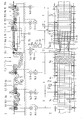
- FIG. 1 shows a mercerizing machine 1 known in terms of its structure, in which a fabric web 2 in a bound web guide passes successively through a hot impregnation zone 3, a cooling zone 4, an exposure zone 5 and a stabilization zone 6.
- the stabilization zone 6 consists of the spreader zone 7, formed by the stenter 8 and a dwell zone 9.
- the fabric web 2 is formed by roller arrangements 3a, 4a, 5a and 9a bound guided, ie that the rollers are in continuous line contact, so that the fabric web is continuously guided and supported under pressure. This ensures that the width of the web cannot collapse during treatment.
- the fabric web 2 is first stretched to the desired width in a run-in area 8a and, in such a spread-out manner, is transferred to the dwell zone 9.
- the clamping frame 8 is a needle clamping frame. In principle, however, other types of stenter frames or spreader devices are also conceivable.
- Spray nozzles 10 and 10a are provided above the tensioning frame 8, through which the fabric web is sprayed in a known manner with hot weak lye in countercurrent, de-leached and thereby stabilized.
- the spray nozzles 10a provided in the area of the inlet field 8a are designed as tubular spray bars with a large number of individual nozzles, as will be explained in more detail in connection with FIG. 5.
- the spray nozzles 10, on the other hand, are known nozzles distributed uniformly over the web.
- the roller arrangements 3a, 4a, 5a and 9a each have drive rollers 11.1 to 11.6, which are driven in a known manner by motors 14.1 to 14.6.
- Known three-phase drives with frequency converters are used as drive systems.
- fabric tension controller rollers 15.1 to 15.5 are provided by which in themselves in a known manner, the fabric tension is determined in each case and a feedback value corresponding to the respective tension is fed to a controller 16.1 to 16.4, which controls the speed of the assigned drive motors 14.1, 14.2, 14.3, 14.5 in such a way that the fabric web is conveyed with a constant tension during its passage .
- the regulators can be preset in a known manner to adjust the fabric tension.
- the fabric tension regulator rollers 15 are arranged in a known manner in such a way that, even with different roller deflections, bound fabric guidance and uniform fabric tension are always guaranteed. Such arrangements are state of the art.
- the tenter frame 8 has a single-needle brush 17 in the inlet and is driven by a motor 18.
- the conveying speed of the stenter motor 18 is varied by a stenter regulator 19 depending on the tension of the fabric web at the exit of the stenter.
- the fabric tension at the tenter frame outlet is, as shown schematically, determined by the fabric tension controller roller 15.4, the tension-dependent output signals of which are fed to the controller 19.
- a free path 12 is provided between the drive roller 11.4 and the inlet of the tenter frame 8, in which the fabric web is transferred freely and unsupported to the inlet field 8a of the tenter frame 8.
- the tensioning frame regulator 19 has a second control output with which the drive motor 11.4 of the last drive roller of the roller arrangement 5a is controlled.
- the controller 19 is provided with a preselection device 20 which allows the signals at the output 19a to be changed compared to the output signals at the output 19b in such a way that the tenter frame motor 18 or the conveying speed of the tenter frame 8 compared to the conveying speed of the motor 14.4 or the last drive roller 11.4 of the action zone 5 can be reduced.
- the transition of the fabric web in the free path 12 can therefore be carried out more loosely or tensioned, depending on the setting of the preselection device 20. Depending on the tension that the fabric web 2 has in the free path 12, it is therefore applied more loosely or stretched to the tensioning frame 8.
- the needles of the tensioning frame 8 thus grip the fabric web with less or greater pretension, which greatly influences the stretching behavior of the goods.
- the spray nozzles 10a are arranged in the inlet area 8a of the tensioning frame 8 in such a way that they only spray the edge region of the fabric web. This means that the edge zones of the fabric web 2 are sprayed so intensively in the conical inlet area that the edge zones R (FIG. 5) of the fabric web 2 are more strongly stabilized than the central zone M.
- a second free path 13 is also provided between an outlet roller 21 and the first drive roller 11.5 of the dwell zone 9.
- the tensioning frame 8 is completely separated from the roller arrangement 9a of the dwell zone 9. This prevents any reaction of the roller zone 9a to the function of the tensioning frame 8.
- the controller 16.4 ensures, based on the feedback from the fabric tension regulator roller 15.5, that the first drive motor 14.5 of the roller arrangement 9a is driven at such a speed that the tension in the free path 13 is constant is kept at a preset value. A loss of width of the fabric web 2 can easily be accepted, since the fabric web can easily be stretched to an excess width in the tensioning frame 8.
- the free path 13 ensures, above all, a perfect transfer of tissue from the stenter 8 to the roller arrangement 9a. A mutual influence, as it could occur through continuously bound goods management, is avoided. Above all, this also ensures that the length of the fabric web 2 can be stretched in a controlled manner when it is pulled off the tensioning frame 8 and is not torn out of the tensioning chain pair 22 by the action of the roller arrangement 9a, by means of which the fabric web in the tensioning frame is stretched wide and with that of the tensioning frame motor 18 certain speed is promoted.
Landscapes
- Engineering & Computer Science (AREA)
- Textile Engineering (AREA)
- Treatment Of Fiber Materials (AREA)
Abstract
Description
Die Erfindung betrifft ein Verfahren und eine Vorrichtung zum Breitstrecken einer Gewebebahn gemäss Oberbegriff von Anspruch 1 bzw. Anspruch 5. Beim Breitstrecken von Gewebebahnen in Mercerisiermaschinen besteht ein bekanntes Problem darin, dass die Streckkräfte unterschiedlich auf die Gewebebahn einwirken, was nach dem Breitstrecken eine ungleichmässige Anordnung der Kettfäden zur Folge hat. Beim kettenlosen Breitstrecken mittels Breitstreckwalzen wird häufig infolge unterschiedlicher Haftreibung vorwiegend die Mittelpartie gestreckt, während die Randzonen leicht eingehen. Beim Breitstrecken in Spannrahmen dagegen besteht häufig die Tendenz, dass nur die äusseren Randpartien verstärkt gestreckt werden. In beiden Fällen tritt eine ungleichmässige Anordnung der Kettfäden auf. Die Erfindung befasst sich nun mit einem Verfahren, bei dem die Gewebebahn zunächst in gebundener Gewebeführung durch Nassbehandlungszonen mit angetriebenen Behandlungsstationen gefördert und dabei imprägniert wird. Anschliessend wird die Gewebebahn in einem Spannrahmen breitgestreckt und dabei gleichzeitig durch Besprühen mit heisser Schwachlauge oder mittels Heissdampf stabilisiert. Vom Spannrahmen wird die Gewebebahn an weitere Nassbehandlungszonen mit angetriebenen Behandlungsstationen abgegeben, wobei sie wieder mit gebundener Gewebeführung geführt wird. Unter gebundener Gewebeführung ist dabei zu verstehen, dass die Warenbahn praktisch ununterbrochen abgestützt und ohne dazwischenliegende freie Strecke von einer Walze auf die nächste übergeben wird. Die Uebergabe der Warenbahn erfolgt praktisch im Bereich der Berührungslinie der beiden Walzen. Durch eine solche Führung wird bezweckt, dass die ausgebreitet durch die Maschine geführte Warenbahn bzw. Gewebebahn während der Be handlung möglichst nicht in der Breite zusammenfallen kann. Aus der CH-PS-531 969 ist z.B. ein solches Verfahren zum Steuern des Durchlaufs einer Warenbahn bekannt.The invention relates to a method and a device for spreading a fabric web according to the preamble of claim 1 and claim 5. When spreading webs in mercerizing machines, a known problem is that the stretching forces act differently on the web, which results in an uneven arrangement after the spreading which results in warp threads. In chainless spreading by means of spreading rollers, the middle section is often stretched mainly due to different static friction, while the edge zones are slightly shrinking. When stretching in tenter frames, on the other hand, there is often a tendency that only the outer edge parts are stretched more. In both cases there is an uneven arrangement of the warp threads. The invention is now concerned with a method in which the fabric web is first conveyed in bound fabric guidance through wet treatment zones with driven treatment stations and is thereby impregnated. The fabric web is then stretched out in a tenter frame and at the same time stabilized by spraying with hot weak lye or using steam. The fabric web is delivered from the stenter to further wet treatment zones with driven treatment stations, whereby it is again guided with a bound fabric guide. Tied fabric guidance is understood to mean that the web of material is supported practically without interruption and passed from one roller to the next with no free space in between. The transfer of the material web takes place practically in the area of the contact line of the two rollers. The purpose of such a guidance is that the web of material or web of fabric spread out through the machine during loading If possible, the action cannot coincide in width. Such a method for controlling the passage of a material web is known from CH-PS-531 969, for example.
Im Spannrahmen, d.h. beim Breitstrecken wird die durch den Imprägnierprozess ausgelöste Gewebeschrumpfung teilweise wieder ausgeglichen.In the stenter, i.e. when stretching, the shrinkage caused by the impregnation process is partially compensated for.
Es hat sich gezeigt, dass ganz allgemein bei Mercerisierprozessen und den verschiedenen Vorbehandlungen, wie Entschlichten, Abkochen und Bleichen die Gewebebahn beim Transport durch die Anlage auch in Längsrichtung verzogen wird, was einen Breiteneinsprung zur Folge hat, der zusätzlich durch den Mercerisierprozess noch erhöht wird.It has been shown that in general in the case of mercerization processes and the various pretreatments such as desizing, boiling and bleaching, the fabric web is also warped in the longitudinal direction during transport through the system, which results in a width increase, which is further increased by the mercerization process.
Der Erfindung liegt die Aufgabe zugrunde, ein verbessertes Verfahren und eine Vorrichtung zum Breitstrecken zu schaffen, bei welchem die Gewebebahn im Spannrahmen selbst schonend auf die geforderte Breite oder sogar eine Ueberbreite gebracht werden kann und wobei gleichmässiges Breitstrecken von Randpartien und Mittelpartie der Gewebebahn erreichbar ist. Mitte-Rand-Differenzen der Kettfadenzahl soll also möglichst ausgeglichen werden können. Erfindungsgemäss wird diese Aufgabe in erster Linie durch ein Verfahren gemäss Kennzeichen von Anspruch I bzw. eine Vorrichtung gemäss Anspruch 5 erreicht.The invention has for its object to provide an improved method and a device for wide stretching, in which the fabric web itself can be gently brought to the required width or even an excess width in the stenter and with uniform wide stretching of the peripheral and middle sections of the fabric web can be achieved. Center-edge differences in the number of warp threads should therefore be able to be compensated for as far as possible. According to the invention, this object is achieved primarily by a method according to the characterizing part of claim I or a device according to
Die Erfindung wendet sich dabei bewusst von der bestehenden Auffassung ab, dass die Gewebebahn bei ihrem Durchlauf durch die Mercerisiermaschine praktisch ununterbrochen abgestützt sein muss, um einen Gewebeeinsprung zu vermeiden. Stattdessen wird der Spannrahmen durch zwei freie Strecken, in denen die Warenbahn ungebunden verläuft, von den Walzenzonen mit gebundener Warenführung "getrennt". Vor allem die freie Strecke im Einlauf des Spannrahmens, ermöglicht es dabei kontrollierte Langenverkürzungen der Gewebebahn vor dem Breitstrecken zuzu lassen, was das Breitstreckverhalten positiv beeinflusst. Es hat sich gezeigt, dass das Breitstreckverhalten umso besser ist, je lockerer die Gewebebahn dem Spannrahmen zugeführt wird. Dies ermöglicht sowohl ein breiteres Strecken der Gewebebahn an sich als auch das Vermeiden von Mitte-Rand-Differenzen der Kettfadenzahl. Dadurch dass wenigstens im Einlauffeld des Spannrahmens dabei zusätzlich die Randzone der Gewebebahn zur Beschleunigung der Stabilisierung in diesem Bereich stärker besprüht werden als deren Mittelzone, werden Mitte-Rand-Differenzen der Kettfadenzahl weiter vermieden. Die Breitstreckkräfte im Spannrahmen werden dabei von den beriets stabilisierten Randzonen in die noch nicht oder erst wenig stabilisierte Mittelzone übertragen, so dass auch die Kettfäden in der Mittelzone auseinander gezogen werden. Die über die freie Strecke zu dem Spannrahmen zugeführte Warenbahn kann also schonend und gleichmässig breitgestreckt werden. Dabei ergibt sich die Möglichkeit, die Gewebebahn im Spannrahmen mit derart geringerer Geschwindigkeit zu fördern als in der vorhergehenden Walzenzone, dass sich die Gewebebahn in der freien Strecke vor dem Spannrahmen kontrolliert verkürzen kann.The invention deliberately turns away from the existing view that the fabric web has to be supported practically without interruption as it passes through the mercerizing machine in order to avoid tissue penetration. Instead, the tenter frame is "separated" from the roller zones with bound goods routing by two free sections, in which the web runs unbound. Above all, the free path in the infeed of the stenter enables controlled length reductions of the fabric web before the wide stretching leave what has a positive effect on spreading behavior. It has been shown that the looser the fabric web is fed to the stenter, the better the spreading behavior. This enables both a wider stretching of the fabric web itself and the avoidance of center-edge differences in the number of warp threads. The fact that at least in the infeed area of the tenter frame additionally sprinkles the edge zone of the fabric web to accelerate the stabilization in this area more strongly than the middle zone thereof, center-edge differences in the number of warp threads are further avoided. The spreading forces in the tenter frame are transferred from the already stabilized marginal zones to the middle zone, which has not yet been stabilized or only slightly stabilized, so that the warp threads in the central zone are also pulled apart. The material web fed to the tenter via the free path can thus be stretched gently and uniformly. This results in the possibility of conveying the fabric web in the tenter frame at such a lower speed than in the preceding roller zone that the fabric web can shorten in a controlled manner in the free path in front of the tenter frame.
Die Breite der stärker mit dem heissen Medium zur Stabilisierung besprühten Randzonen kann je nach Mercerisierprozess und Qualität des zu streckenden Gewebes je etwa 10 % bis 40 % der Gesamtbreite betragen. Vorteilhaft ist es dabei, wenn die Sprühdüsen relativ zur Gewebebahn verstellbar oder ver schwenkbar angeordnet sind, so dass sich zur Ermittlung des optimalen Stabilisier- und Breitstreckverhältnis die Sprühintensität und die Breite der stärker besprühten Randzonen verändern lässt.Depending on the mercerization process and the quality of the fabric to be stretched, the width of the edge zones sprayed more with the hot medium for stabilization can be approximately 10% to 40% of the total width. It is advantageous if the spray nozzles are arranged to be adjustable or pivotable ver relative to the fabric web, so that the spray intensity and the width of the more sprayed edge zones can be changed to determine the optimal stabilization and spreading ratio.
In vielen Fällen führt es dabei zu guten Ergebnissen, wenn im Einlauffeld des Spannrahmens nur die Randzonen direkt mit dem Stabilisierungsmedium besprüht werden und über die restliche Länge des Spannrahmens die Gewebebahn gleichmässig über die gesamte Breite besprüht wird. Es kann aber in Abhängigkeit vom Stabilisierverhalten der Gewebebahn auch vorteilhaft sein, im Einlauffeld auch die Mittelzone zu besprühen und die Randzonen um wenigstens den Faktor 2 stärker zu besprühen, als die Mittelzone. Auch kann es vorteilhaft sein, die Randzonen über die gesamte Länge des Spannrahmens stärker zu besprühen als die Mittelzone.In many cases, it leads to good results if only the edge zones are sprayed directly with the stabilizing medium in the infeed area of the stenter and the fabric web is evenly distributed over the remaining length of the stenter entire width is sprayed. Depending on the stabilization behavior of the fabric web, however, it can also be advantageous to spray the middle zone in the inlet area and to spray the edge zones at least by a factor of 2 more than the middle zone. It can also be advantageous to spray the edge zones more strongly over the entire length of the tenter than the central zone.
Die Erfindung ermöglicht dabei sogar ein Breitstrecken über die gewünschte Rohbreite hinaus. In Verbindung mit der differenzierten Stabilisierung im Spannrahmen ermöglicht dies die Uebergabe in der zweiten freien Strecke an die nachfolgende Walzenanordnung mit gebundener Warenführung. Aufgrund des verbesserten Breitstreckverhaltens im Spannrahmen sowie der weitgehenden Stabilisierung ist dabei nur mit einem unwesentlichen, im Spannrahmen kompensierbaren Breiteneinsprung im Bereich der zweiten freien Strecke zu rechnen. Der Fachmann kann dabei die Geschwindigkeit der dem Spannrahmen nachgeordneten Walzenanordnung so wählen, dass der Gewebezug in der zweiten freien Strecke dem gewünschten Wert entspricht. Derartige Zugregelanordnungen sind dem Fachmann bekannt und gebräuchlich. Dadurch lässt sich auch erreichen, dass sich die Geschwindigkeit des Spannrahmens ausschliesslich unter Berücksichtigung des gewünschten Breitstreckverhaltens regeln lässt und dass keine nachteilige Rückwirkung der Geschwindigkeit der dem Spannrahmen nachfolgenden Walzenanordnung auf die Spannrahmen-Abzugsgeschwindigkeit erfolgt. Durch höheren Zug auf die Gewebebahn in der zweiten freien Strecke, d.h. nach dem Spannrahmen lässt sich ausserdem vorteilhaft Einfluss auf die Längsdehnung der Gewebebahn nehmen.The invention even enables wide stretching beyond the desired raw width. In conjunction with the differentiated stabilization in the stenter, this enables the transfer in the second free stretch to the subsequent roller arrangement with bound goods guidance. Due to the improved spreading behavior in the stenter as well as the extensive stabilization, only an insignificant, in the stenter compensated width increase in the area of the second free stretch can be expected. The person skilled in the art can select the speed of the roller arrangement downstream of the stenter frame so that the fabric tension in the second free path corresponds to the desired value. Train control arrangements of this type are known and customary to the person skilled in the art. This also means that the speed of the stenter can only be regulated taking into account the desired spreading behavior and that there is no adverse effect of the speed of the roller arrangement following the stenter on the stenter pull-off speed. By pulling higher on the fabric web in the second free stretch, i.e. after the stenter, it is also advantageous to influence the longitudinal stretch of the fabric web.
Praktisch lässt sich die "Trennung" des Spannrahmens von den nachfolgenden Antrieben und die Zugregelung im Spannrahmenauslauf besonders vorteilhaft realisieren, wenn im Spannrahmenauslauf vor der zweiten freien Strecke eine Zugmessanordnung zur Kontrolle des auf die Gewebebahn von einer nachfol genden Zugwalze ausgeübten Zugs vorgesehen ist und wenn die Zugmessanordnung über eine Regeleinrichtung mit der Antriebseinrichtung des Spannrahmens zu dessen Geschwindigkeitsregelung in Abhängigkeit vom derart gemessenen Zug der Gewebebahn in der freien Strecke vorgesehen ist. Auf diese Weise lässt sich der Zug der Gewebebahn in der freien Strecke im Auslauf des Spannrahmens einstellen und konstant halten.In practice, the "separation" of the tenter frame from the subsequent drives and the tension control in the tenter frame outlet can be realized particularly advantageously if a tension measurement arrangement in the tenter frame outlet before the second free path to check that the fabric web is trailing the pulling roller exerted is provided and if the tension measuring arrangement is provided via a control device with the drive device of the tensioning frame for its speed control in dependence on the tension of the fabric web measured in this way in the free path. In this way, the tension of the fabric web in the free path in the outlet of the stenter can be adjusted and kept constant.
Die Erfindung ist im folgenden in Ausführungsbeispielen anhand der Zeichnungen näher erläutert. Es zeigen:
- Figur 1 Die schematische Darstellung einer Mercerisiermaschine mit Spannrahmen mit den Merkmalen der Erfindung in Seitenansicht,
Figur 2 eine Draufsicht auf die Mercerisiermaschine gemäss Figur 1,Figur 3 eine schematische Darstellung des Breitenverhaltens der Gewebebahn in ihrem Durchlauf durch die Behandlungsstationen gemäss Figur 1 und 2,Figur 4 eine schematische Darstellung eines Längenverhaltens der Gewebebahn bei ihrem Durchlauf durch die Mercerisiermaschine gemäss Figur 1,Figur 5 eine Darstellung der Sprühdüsen im Bereich des Einlauffelds der Mercerisiermaschine gemäss Figur 1,Figur 6 ein abgewandeltes Ausführungsbeispiel einer Anordnung zum Besprühen der Gewebebahn mit Heisslauge undFigur 7 die schematische Darstellung der Mengenverteilung der auf dieGewebebahn 2 aufgebrachten Heisslauge.
- FIG. 1 shows a schematic illustration of a mercerizing machine with a clamping frame with the features of the invention in a side view,
- FIG. 2 shows a plan view of the mercerizing machine according to FIG. 1,
- FIG. 3 shows a schematic representation of the width behavior of the fabric web in its passage through the treatment stations according to FIGS. 1 and 2,
- FIG. 4 shows a schematic representation of a length behavior of the fabric web as it passes through the mercerizing machine according to FIG. 1,
- FIG. 5 shows the spray nozzles in the area of the inlet field of the mercerizing machine according to FIG. 1,
- Figure 6 shows a modified embodiment of an arrangement for spraying the fabric web with hot water and
- FIG. 7 shows the schematic representation of the quantity distribution of the hot liquor applied to the
fabric web 2.
Figur 1 zeigt eine vom Aufbau her bekannte Mercerisiermaschine 1, bei der eine Gewebebahn 2 in gebundener Bahnführung nacheinander eine Heissimprägnierzone 3, eine Kühlzone 4, eine Einwirkzone 5 und eine Stabilisierzone 6 durchläuft. Die Stabilisierzone 6 besteht dabei aus der Breitstreckzone 7, gebildet durch den Spannrahmen 8 und aus einer Verweilzone 9. In der Heissimprägnierzone 3, der Kühlzone 4, der Einwirkzone 5 sowie der Verweilzone 9 wird die Gewebebahn 2 durch Walzenanordnungen 3a, 4a, 5a und 9a gebunden geführt, d.h., dass sich die Walzen durchgehend linienförmig berühren, so dass die Gewebebahn durchgehend flächig unter Druck geführt und abgestützt wird. Dadurch wird erreicht, dass die Warenbahn während der Behandlung nicht in der Breite zusammenfallen kann. Im Spannrahmen 8 wird die Gewebebahn 2 zunächst in einem Einlauffeld 8a auf die gewünschte Breite gestreckt und derart ausgebreitet der Verweilzone 9 übergeben. Beim Ausführungsbeispiel ist der Spannrahmen 8 ein Nadelspannrahmen. Grundsätzlich sind aber auch andere Typen von Spannrahmen oder Breitstreckvorrichtungen denkbar.FIG. 1 shows a mercerizing machine 1 known in terms of its structure, in which a
Ueber dem Spannrahmen 8 sind Sprühdüsen 10 und 10a vorgesehen, durch welche die Gewebebahn in bekannter Weise mit heisser Schwachlauge im Gegenstrom besprüht, entlaugt und dabei stabilisiert wird. Die im Bereich des Einlauffelds 8a vorgesehenen Sprühdüsen 10a sind dabei als rohrförmig ausgebildete Sprühbalken mit einer Vielzahl von Einzeldüsen ausgebildet, wie dies im Zusammenhang mit Figur 5 noch näher erläutert wird. Die Sprühdüsen 10 dagegen sind bekannte, gleichmässig über der Warenbahn verteilte Düsen.
Die Walzenanordnungen 3a, 4a, 5a und 9a weisen jeweils Antriebswalzen 11.1 bis 11.6 auf, die in bekannter Weise durch Motore 14.1 bis 14.6 angetrieben werden. Als Antriebssysteme werden dabei bekannte Drehstromantriebe mit Frequenzumrichter verwendet. In den Walzenanordnungen sind dabei Gewebezugreglerwalzen 15.1 bis 15.5 vorgesehen durch welche in an sich bekannter Weise der Gewebezug jeweils ermittelt und ein dem jeweiligen Zug entsprechender Rückführwert je einem Regler 16.1 bis 16.4 zugeführt wird, welcher die Drehzahl der zugeordneten Antriebsmotore 14.1, 14.2, 14.3, 14.5 derart regelt, dass die Gewebebahn bei ihrem Durchlauf mit einem konstanten Zug gefördert wird. Zur Einstellung des Gewebezugs können die Regler dabei in bekannter Weise voreinstellbar sein. Die Gewebezugreglerwalzen 15 sind in bekannter Weise so angeordnet, dass auch bei unterschiedlicher Walzenauslenkung immer eine gebundene Gewebeführung und gleichmässiger Gewebezug gewährleistet wird. Solche Anordnungen sind Stand der Technik.The
Der Spannrahmen 8 weist im Einlauf eine Einnadelbürste 17 auf, und wird durch einen Motor 18 angetrieben. Die Fördergeschwindigkeit des Spannrahmenmotors 18 wird durch einen Spannrahmen-Regler 19 in Abhängigkeit vom Zug der Gewebebahn am Ausgang des Spannrahmens variiert. Der Gewebezug am Spannrahmen-Auslauf wird, wie schematisch dargestellt, durch die Gewebezugreglerwalze 15.4 ermittelt, deren zugabhängige Ausgangssignale dem Regler 19 zugeführt werden.The
Im Gegensatz zur gebundenen Gewebeführung in den Walzenanordnungen vor und nach dem Spannrahmen 8 ist zwischen der Antriebswalze 11.4 und dem Einlauf des Spannrahmens 8 eine freie Strecke 12 vorgesehen in welcher die Gewebebahn frei und ungestützt dem Einlauffeld 8a des Spannrahmens 8 übergeben wird. Wie in Figur 1 schematisch dargestellt ist, weist der Spannrahmen-Regler 19 einen zweiten Steuerausgang auf, mit welchem der Antriebsmotor 11.4 der letzten Antriebswalze der Walzenanordnung 5a angesteuert wird. Der Regler 19 ist dabei mit einer Vorwahleinrichtung 20 versehen, welche es erlaubt, die Signale am Ausgang 19a gegenüber den Ausgangssignalen am Ausgang 19b derart zu verändern, dass der Spannrahmenmotor 18 bzw. die Fördergeschwindigkeit des Spannrahmens 8 gegenüber der Fördergeschwindigkeit des Motors 14.4 bzw. der letzten Antriebswalze 11.4 der Einwirkzone 5 reduziert werden kann. Der Uebergang der Gewebebahn in der freien Strecke 12 kann also je nach Einstellung der Vorwahleinrichtung 20 loser oder gespannter erfolgen. Je nachdem, welche Spannung dabei die Gewebebahn 2 in der freien Strecke 12 aufweist wird sie also loser oder gestreckter auf den Spannrahmen 8 aufgebracht. Die Nadeln des Spannrahmens 8 erfassen die Gewebebahn damit mit geringerer oder grösserer Vorspannung, was das Streckverhalten der Ware stark beeinflusst. Durch anschliessendes Spannen auf die gewünschte Breite sowie Stabilisieren mit den Spritzrohren 10 und 10a lässt sich die Gewebebahn sowohl in der Länge als auch in der Breite stabilisieren. Durch die relativ lockere Uebergabe im Spannrahmeneinlauf wird dabei vorteilhaft erreicht, dass der Verzug der Kettfäden minimiert wird. Wie vor allem aus Figur 2 und 5 ersichtlich ist, sind dabei die Sprühdüsen 10a im Einlauffeld 8a des Spannrahmens 8 derart angeordnet, dass sie lediglich den Randbereich der Gewebebahn besprühen. Dies bedeutet, dass im konischen Einlauffeld die Randzonen der Gewebebahn 2 derart intensiv besprüht werden, dass die Randzonen R (Figur 5) der Gewebebahn 2 stärker stabilisiert werden als die Mittelzone M. Dies hat zur Folge, dass sich die von den Spannketten verursachten Breitstreckkräfte von den bereits stabilisierten Randzonen R in die noch nicht oder erst wenig stabilisierte Mittelzone M übertragen. Dies ergibt eine etwa gleichmässige Streckkraft über die gesamte Breite der Gewebebahn, so dass auch die Kettfäden in der Mittelzone M auseinander gezogen werden. Die selektive Stabilisierung der Randzonen R in Verbindung mit der freien Uebergabe der Gewebebahn 2 in der freien Strecke 12 erlaubt eine bisher nicht erreichbare Optimierung des Breitstreckverhaltens der Gewebebahn.In contrast to the bound fabric guide in the roller arrangements before and after the
Selbstverständlich ist es auch möglich, statt des Spannrahmenreglers 19 zwei separate Regler einzusetzen, von denen einer den Spannrahmenmotor 18 und einer den Motor 14.4 der letzten Zugwalze bzw. Antriebswalze 11.4 vor der freien Strecke 12 ansteuert. Dabei ist lediglich von Bedeutung, dass dann beide Regler ihr Rückführsignal von der Gewebezugreglerwalze 15.4 im Spannrahmenauslauf erhalten.Of course, it is also possible to use two separate controllers instead of the
Im Auslauf des Spannrahmens 8 ist ausserdem eine zweite freie Strecke 13 zwischen einer Auslaufwalze 21 und der ersten Antriebswalze 11.5 der Verweilzone 9 vorgesehen. Durch diese freie Strecke 13 mit ungebundener Führung der Gewebebahn 2 wird der Spannrahmen 8 vollständig von der Walzenanordnung 9a der Verweilzone 9 getrennt. Dies verhindert jegliche Rückwirkung der Walzenzone 9a auf die Funktion des Spannrahmens 8. Der Regler 16.4 gewährleistet dabei aufgrund der Rückmeldung der Gewebezugreglerwalze 15.5, dass der erste Antriebsmotor 14.5 der Walzenanordnung 9a mit einer solchen Geschwindigkeit angetrieben wird, dass der Zug in der freien Strecke 13 konstant auf einem voreinstellbaren Wert gehalten wird. Dabei kann ein Breitenverlust der Gewebebahn 2 ohne weiteres in Kauf genommen werden, da sich im Spannrahmen 8 die Gewebebahn ohne weiteres auf Ueberbreite spannen lässt. Durch die freie Strecke 13 wird vor allem eine einwandfreie Gewebeübergabe vom Spannrahmen 8 auf die Walzenanordnung 9a sichergestellt. Eine gegenseitige Beeinflussung, wie sie durch durchgehend gebundene Warenführung auftreten könnte, wird vermieden. Vor allem wird dadurch auch gewährleistet, dass die Gewebebahn 2 beim Abzug vom Spannrahmen 8 kontrolliert in der Länge gestreckt werden kann und dabei nicht durch Rückwirkung der Walzenanordnung 9a aus dem Spannkettenpaar 22 gerissen wird, durch welches die Gewebebahn im Spannrahmen breitgestreckt und mit der vom Spannrahmenmotor 18 bestimmten Geschwindigkeit gefördert wird.In the outlet of the
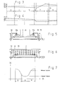
Figur 3 zeigt schematisch, wie sich die Gewebebreite der Gewebebahn 2 beim Durchlauf durch die Mercerisiermaschine 1 verhalten kann. Mit 24 ist dabei der Wert der Gewebebreite (Längeneinheit) bezeichnet. 25 stellt die beim Ausführungsbeispiel gewünschte Gewebe-Soll-Breite dar und 26 zeigt den Verlauf der Gewebe-Ist-Breite. Wie im Diagramm schematisch dargestellt ist, liegt beim Eintritt der Gewebebahn 2 in die Mercerisiermaschine 1 bereits ein spürbarer Breitenverlust vor. Dieser resultiert aus der Durchtränkung der Ware mit flüssigen Medien und aus dem Gewebezug beim Transport durch verschiedene Vorbehandlungs-Stufen. Der Breitenverlust nimmt in den Zonen 3, 4 und 5 trotz der gebundenen Bahnführung noch etwas zu. In der freien Strecke 12 zwischen der letzten Antriebswalze 11.4 der Walzenanordnung 5a (Figur 1) und dem Einlauf in den Spannrahmen 8 nimmt der Breitenverlust stark zu. Dies resultiert aus der ungebundenen lockeren Gewebeführung in diesem Bereich. In der Breitstreckzone 7 wird dann die Gewebebahn derart ausgebreitet, dass sie mit Uebermass den Spannrahmen 8 verlässt. Die Ware ist dabei bereits teilweise stabilisiert. Das Uebermass wird trotzdem eingestellt, weil in der Walzenanordnung 9a bzw. der Verweilzone 9 bis zur endgültigen Stabilisierung noch mit Breitenverlust zu rechnen ist. Auch in der freien Strecke 13, in der die Gewebebahn ungebunden zwischen der Auslaufwalze 21 des Spannrahmens 8 und der ersten Antriebswalze 11.5. der Walzenanordnung 9a (Figur 1) verläuft, findet ein Breitenverlust statt. Aufgrund der Stabilisierung der Gewebebahn im Spannrahmen 8 ist dieser Breitenverlust allerdings nicht so stark, wie der Breitenverlust in der freien Strecke 12.FIG. 3 shows schematically how the fabric width of the
Figur 4 zeigt schematisch, wie sich die Gewebebahn 2 beim Durchlauf durch die Mercerisiermaschine 1 bezüglich ihrer Gewebelänge 27 (Längeneinheit) verhält. Im Diagramm ist mit 28 der Verlauf der jeweiligen Gewebe-Ist-Länge und mit 29 die gewünschte Gewebe-Soll-Länge bezeichnet.FIG. 4 shows schematically how the
Wie schematisch dargestellt, tritt die Gewebebahn 2 durch die Vorbehandlung bereits verstreckt und mit Ueberlänge in die Mercerisiermaschine 1 ein. Durch entsprechende Zug-Wert-Vorgabe mittels der Regler 16.1, 16.2 und 16.3 (Figur 1) kann bereits vor der freien Strecke 12 eine Längenverkürzung zuge lassen werden. Im Bereich der freien Strecke 12 kann sich fur die Gewebebahn durch die nicht gebundene Gewebeführung und die Differenz der Fördergeschwindigkeit des Spannrahmens 8 und der Antriebswalze 11.4 (Figur 1) eine Verkürzung bis unter den Sollwert ergeben. Beim Durchlauf durch den Spannrahmen 8 bzw. die Breitstreckzone 7 bleibt die Gewebelänge konstant, da die Gewebebahn 2 fest im Spannkettenpaar 22 (Figur 2) eingespannt ist. Dagegen tritt in der freien Strecke 13 zwischen der Auslaufwalze 21 und der ersten Antriebswalze 11.5 der Walzenanordnung 9a der Verweilzone 9 eine Dehnung des Gewebes in Längsrichtung auf, weil dort die Gewebebahn 2 mit Spannung vom Spannrahmenauslauf abgezogen wird. In der Verweilzone 9 ergibt sich eine weitere Dehnung in Längsrichtung, die auf die Spannung beim Gewebetransport zurückzuführen ist.As shown schematically, the
Figur 5 zeigt einen vereinfachten Schnitt längs der Linie A-A in Figur 2, bei der aus Gründen der Uebersichtlichkeit nur die für die Darstellung der Sprühbalken 10a wesentlichen Elemente gezeichnet sind. Die Sprühbalken 10a sind gemass Figur 2 etwa im gleichen Winkel wie das Einlauffeld 8a des Spannrahmens 8 angeordnet. Die Sprühbalken 8a weisen jeweils ein über der Gewebebahn 2 angeordnetes Rohr auf welches durch nicht dargestellte Versorgungsleitungen mit heisser Schwachlauge versorgt wird. An der Unterseite sind die Sprühbalken 10a mit nicht näher dargestellten Sprühdüsen, z.B. in der Form einfacher Bohrungen versehen, welche eine von der Randzone R zur Mittelzone M hin abnehmende Sprühdichte erzielen. Damit die Sprühbalken 10a an unterschiedliche Gewebebahnbreiten angepasst werden können, sind sie mittels Halterungen 30 an einer mit einem Motor 31 antreibbaren gegenläufigen Spindel 36 befestigt, durch welche die Halterungen 30 quer zur Gewebebahn 2 bewegt und dadurch justiert werden können. Dadurch wird die Gewebebahn 2, wie bereits vorstehend beschrieben, im Bereich des Einlauffelds 8a vorwiegend in den Randzonen R besprüht. Besonders vorteilhaft ist dabei die Düsenan ordnung so gewählt, dass die Sprühdichte auch im Bereich der Randzone R selbst vom Rand her zum Bereich der Mittelzone zunimmt.FIG. 5 shows a simplified section along the line AA in FIG. 2, in which, for reasons of clarity, only the elements essential for the representation of the spray bars 10a are drawn. The spray bars 10a are arranged according to FIG. 2 at approximately the same angle as the
Bei der Ausführungsvariante gemäss Figur 6 ist quer zur Gewebebahn 2 eine Vielzahl von Sprühdüsen 10 angeordnet, die jeweils über eine Sammelleitung 32 mit Heisslauge gespeist werden. Die Sammelleitungen 32 bzw. die Sprühdüsen 10 sind analog dem Ausführungsbeispiel gemäss Figur 1 in mehreren Reihen über die gesamte Länge des Spannrahmens 8 einschliesslich des Einlauffelds 8a verteilt angeordnet. Sprühbalken 10a gemäss Figur 1 und 2 sind dabei nicht vorgesehen. Jede Sprühdüse 10 ist dabei über ein verstellbares Ventil 33 mit der Sammelleitung 32 verbunden. Durch Verstellen des Ventils 33 lässt sich die Durchflussmenge der heissen Schwachlauge steuern und damit die Sprühdichte auf die Gewebebahn 2 einstellen. Diese Verteilung ist in Figur 7 dargestellt. In Richtung des Pfeils 34 ist dabei die Laugenmenge und in Richtung des Pfeils 35 die Gewebebahnbreite dargestellt. Wie gezeigt, betragen die Randzonen R jeweils etwa 30% der Gesamtbreite der Gewebebahn. In den äussersten Bereich der Randzone wird etwa dreimal soviel Schwachlauge aufgetragen wie in der Mittelzone M. Die Gesamtmenge, d.h. der Mittelwert der Laugenmenge in den Randzonen ist etwa doppelt so gross wie der in der Mittelzone aufgetragene Laugenanteil.In the embodiment variant according to FIG. 6, a plurality of
Durch die dargestellte Verteilung der Laugenmenge, insbesondere auch durch die kontinuierliche Zunahme der Sprühdichte im Randbereich selbst wird auf vorteilhafteste Weise erreicht, dass zunächst in den Randzonen R, die vor allem den Streckkräften des Spannrahmens ausgesetzt sind, beschleunigt eine Stabilisierung eintritt. Je mehr diese Stabilisierung in den Randzonen R fortschreitet, desto stärker werden die Streckkräfte auf die Mittelzone M weitergeleitet, so dass auch dort die gewünschte Streckung stattfindet was zu gleichmässiger Verteilung der in Figur 6 mit 2a angedeuteten Kett fäden führt. Selbstverständlich lässt sich die Breite der Randzonen R und der Mittelzone M an die spezifischen Erfordernisse einer bestimmten Ware und eines bestimmten Mercerisierprozesses anpassen. Dazu müssen lediglich die Ventile 33 zur Dosierung der Laugenmenge entsprechend eingestellt werden, um schmälere oder breitere Randzonen R und stärkeren oder reduzierteren Abfall der Laugenmenge zur Mittelzone hin zu erreichen. Die Reduzierung der Laugenzone in der Mittelzone M kann dabei z.B. wie beim Ausführungsbeispiel gemäss Figur 1 nur im Einlauffeld 8a des Spannrahmens stattfinden oder aber sie kann über die gesamte Länge des Spannrahmens 8 gleichmässig oder kontinuierlich abnehmend beibehalten werden.The distribution of the amount of lye shown, in particular also by the continuous increase in the spray density in the edge area itself, advantageously achieves the effect that stabilization occurs first in the edge zones R, which are primarily exposed to the stretching forces of the tenter frame. The more this stabilization progresses in the edge zones R, the more the stretching forces are transmitted to the middle zone M, so that the desired stretching also takes place there, resulting in a uniform distribution of the warp indicated in FIG. 6 with 2a leads. Of course, the width of the edge zones R and the central zone M can be adapted to the specific requirements of a specific product and a specific mercerization process. For this purpose, only the
Claims (10)
- die Gewebebahn dem Spannrahmen von der vorhergehenden Nassbehandlungszone über eine freie Strecke mit ungebundener Bahnführung zugeführt wird,
- die Gewebebahn vom Spannrahmen über eine zweite freie Strecke der nachfolgenden Nassbehandlungsstation weitergeleitet wird,
- und dass wenigstens im Einlauffeld des Spannrahmens die Randzonen der Gewebebahn zur Beschleunigung der Stabilisierung in diesem Bereich stärker besprüht werden als deren Mittelzone.1. A method for spreading a fabric web in a mercerizing machine, the fabric web first being conveyed in a bound fabric guide through at least one wet treatment zone with driven treatment stations and thereby being impregnated and then being fed to a stenter and being passed on from there to a further wet treatment zone with driven treatment stations with bound fabric guide , wherein the fabric web is sprayed with stabilizing spray nozzles arranged above the clamping frame with a hot medium, characterized in that
the fabric web is fed to the tenter from the previous wet treatment zone over a free stretch with an unbound web guide,
the fabric web is forwarded from the stenter over a second free stretch to the subsequent wet treatment station,
- And that, at least in the inlet area of the stenter, the edge zones of the fabric web are sprayed more strongly in this area to accelerate the stabilization than their central zone.
Applications Claiming Priority (2)
| Application Number | Priority Date | Filing Date | Title |
|---|---|---|---|
| CH1607/88 | 1988-04-29 | ||
| CH160788 | 1988-04-29 |
Publications (2)
| Publication Number | Publication Date |
|---|---|
| EP0340166A1 true EP0340166A1 (en) | 1989-11-02 |
| EP0340166B1 EP0340166B1 (en) | 1992-06-17 |
Family
ID=4214384
Family Applications (1)
| Application Number | Title | Priority Date | Filing Date |
|---|---|---|---|
| EP19890810276 Expired - Lifetime EP0340166B1 (en) | 1988-04-29 | 1989-04-11 | Method and device for the widthwise stretching of a fabric in a mercerising installation |
Country Status (2)
| Country | Link |
|---|---|
| EP (1) | EP0340166B1 (en) |
| DE (1) | DE58901667D1 (en) |
Cited By (1)
| Publication number | Priority date | Publication date | Assignee | Title |
|---|---|---|---|---|
| EP0945539A1 (en) * | 1998-03-26 | 1999-09-29 | Textilforschungsinstitut Thüringer-Vogtland e.V. | Method and device for continuous alkali treatment |
Citations (3)
| Publication number | Priority date | Publication date | Assignee | Title |
|---|---|---|---|---|
| CH531969A (en) * | 1971-06-02 | 1972-12-31 | Benninger Ag Maschf | Method and device for controlling the passage of a web of material through a treatment line formed by individually driven treatment stations or groups of such stations |
| US4022574A (en) * | 1974-05-10 | 1977-05-10 | Daido-Maruta Finishing Co. Ltd. | Method for treating knitted fabrics containing cotton fibers with alkali hydroxides |
| EP0198793A1 (en) * | 1985-03-21 | 1986-10-22 | Benninger AG | Method and apparatus for mercerising fabrics |
-
1989
- 1989-04-11 EP EP19890810276 patent/EP0340166B1/en not_active Expired - Lifetime
- 1989-04-11 DE DE8989810276T patent/DE58901667D1/en not_active Expired - Fee Related
Patent Citations (3)
| Publication number | Priority date | Publication date | Assignee | Title |
|---|---|---|---|---|
| CH531969A (en) * | 1971-06-02 | 1972-12-31 | Benninger Ag Maschf | Method and device for controlling the passage of a web of material through a treatment line formed by individually driven treatment stations or groups of such stations |
| US4022574A (en) * | 1974-05-10 | 1977-05-10 | Daido-Maruta Finishing Co. Ltd. | Method for treating knitted fabrics containing cotton fibers with alkali hydroxides |
| EP0198793A1 (en) * | 1985-03-21 | 1986-10-22 | Benninger AG | Method and apparatus for mercerising fabrics |
Cited By (2)
| Publication number | Priority date | Publication date | Assignee | Title |
|---|---|---|---|---|
| EP0945539A1 (en) * | 1998-03-26 | 1999-09-29 | Textilforschungsinstitut Thüringer-Vogtland e.V. | Method and device for continuous alkali treatment |
| DE19813237C2 (en) * | 1998-03-26 | 2000-05-04 | Titv Greiz | Method and device for continuous alkali treatment |
Also Published As
| Publication number | Publication date |
|---|---|
| DE58901667D1 (en) | 1992-07-23 |
| EP0340166B1 (en) | 1992-06-17 |
Similar Documents
| Publication | Publication Date | Title |
|---|---|---|
| DE709924C (en) | Device arranged on a textile machine for separating the adhering threads of a rubber tape | |
| DE3025154A1 (en) | METHOD AND DEVICE FOR MAINTAINING A MOVING TEXTILE MATERIAL | |
| EP0072453A2 (en) | Process and device for the manufacture of a laid sheet | |
| EP1573110B1 (en) | Device for finishing denim woven fabric | |
| DE3300934C2 (en) | ||
| DE4229535C2 (en) | Process for shrinking biaxially stretched thermoplastic film webs and device for carrying out the process | |
| EP0340166B1 (en) | Method and device for the widthwise stretching of a fabric in a mercerising installation | |
| DE3602968C2 (en) | ||
| EP0305326B1 (en) | Method and apparatus for mercerizing a fabric | |
| DE3805267A1 (en) | DEVICE FOR CONTINUOUSLY DETECTING TISSUE IN AN AUTOCLAVE | |
| DE1785114A1 (en) | Method and apparatus for opening a crimped yarn | |
| DE2314889A1 (en) | Tyre cord preparation process - has cutting blade to sever wefts from a woven leaving warps | |
| DE2336518B2 (en) | DEVICE FOR TREATMENT OF WEB CHAINS | |
| EP0335833B1 (en) | Method and apparatus for stretching a fabric in width | |
| DE1951625A1 (en) | Tricot fabric drying plant | |
| WO2010078663A2 (en) | Knitting machine, in particular crochet galloon machine, and method for producing strips | |
| DE2613446A1 (en) | Sizing and/or dyeing agent control - has a control valve to regulate squeeze roller pressure to give a constant content in fibre strands | |
| DE2417409A1 (en) | Textile web warp distortion correcting device - with two sets of cylinders each formed by three sections arranged for selective driving | |
| DE1934346A1 (en) | Steam setting woven yarns | |
| DE662768C (en) | Method and device for equalizing the longitudinal tension of the knitted fabric in the inlet area in tensioning, creaming and drying machines | |
| DE2650283C2 (en) | Control device on a machine for manufacturing filter rods | |
| DD126355B1 (en) | METHOD AND DEVICE FOR OPERATING CHAIN EQUIPMENT | |
| CH595498A5 (en) | Mercerising fabric stretching | |
| DE2304288C3 (en) | Web guiding device | |
| DE2732156A1 (en) | DEVICE FOR BALANCING THE THREAD TENSION |
Legal Events
| Date | Code | Title | Description |
|---|---|---|---|
| PUAI | Public reference made under article 153(3) epc to a published international application that has entered the european phase |
Free format text: ORIGINAL CODE: 0009012 |
|
| AK | Designated contracting states |
Kind code of ref document: A1 Designated state(s): BE CH DE ES FR IT LI NL |
|
| 17P | Request for examination filed |
Effective date: 19900305 |
|
| 17Q | First examination report despatched |
Effective date: 19910827 |
|
| ITF | It: translation for a ep patent filed |
Owner name: LENZI & C. |
|
| GRAA | (expected) grant |
Free format text: ORIGINAL CODE: 0009210 |
|
| AK | Designated contracting states |
Kind code of ref document: B1 Designated state(s): BE CH DE ES FR IT LI NL |
|
| PG25 | Lapsed in a contracting state [announced via postgrant information from national office to epo] |
Ref country code: NL Effective date: 19920617 Ref country code: ES Free format text: THE PATENT HAS BEEN ANNULLED BY A DECISION OF A NATIONAL AUTHORITY Effective date: 19920617 Ref country code: BE Effective date: 19920617 |
|
| REF | Corresponds to: |
Ref document number: 58901667 Country of ref document: DE Date of ref document: 19920723 |
|
| ET | Fr: translation filed | ||
| NLV1 | Nl: lapsed or annulled due to failure to fulfill the requirements of art. 29p and 29m of the patents act | ||
| PLBI | Opposition filed |
Free format text: ORIGINAL CODE: 0009260 |
|
| 26 | Opposition filed |
Opponent name: RAMISCH KLEINEWEFERS GMBH Effective date: 19930316 |
|
| PLBN | Opposition rejected |
Free format text: ORIGINAL CODE: 0009273 |
|
| STAA | Information on the status of an ep patent application or granted ep patent |
Free format text: STATUS: OPPOSITION REJECTED |
|
| 27O | Opposition rejected |
Effective date: 19951102 |
|
| PGFP | Annual fee paid to national office [announced via postgrant information from national office to epo] |
Ref country code: FR Payment date: 20060313 Year of fee payment: 18 |
|
| PGFP | Annual fee paid to national office [announced via postgrant information from national office to epo] |
Ref country code: DE Payment date: 20060317 Year of fee payment: 18 |
|
| PGFP | Annual fee paid to national office [announced via postgrant information from national office to epo] |
Ref country code: IT Payment date: 20060430 Year of fee payment: 18 |
|
| PGFP | Annual fee paid to national office [announced via postgrant information from national office to epo] |
Ref country code: CH Payment date: 20060623 Year of fee payment: 18 |
|
| REG | Reference to a national code |
Ref country code: CH Ref legal event code: PL |
|
| PG25 | Lapsed in a contracting state [announced via postgrant information from national office to epo] |
Ref country code: DE Free format text: LAPSE BECAUSE OF NON-PAYMENT OF DUE FEES Effective date: 20071101 |
|
| PG25 | Lapsed in a contracting state [announced via postgrant information from national office to epo] |
Ref country code: CH Free format text: LAPSE BECAUSE OF NON-PAYMENT OF DUE FEES Effective date: 20070430 Ref country code: LI Free format text: LAPSE BECAUSE OF NON-PAYMENT OF DUE FEES Effective date: 20070430 |
|
| PG25 | Lapsed in a contracting state [announced via postgrant information from national office to epo] |
Ref country code: FR Free format text: LAPSE BECAUSE OF NON-PAYMENT OF DUE FEES Effective date: 20070430 |
|
| PG25 | Lapsed in a contracting state [announced via postgrant information from national office to epo] |
Ref country code: IT Free format text: LAPSE BECAUSE OF NON-PAYMENT OF DUE FEES Effective date: 20070411 |