EP0339937B1 - Informationsanzeigevorrichtung - Google Patents
Informationsanzeigevorrichtung Download PDFInfo
- Publication number
- EP0339937B1 EP0339937B1 EP89304113A EP89304113A EP0339937B1 EP 0339937 B1 EP0339937 B1 EP 0339937B1 EP 89304113 A EP89304113 A EP 89304113A EP 89304113 A EP89304113 A EP 89304113A EP 0339937 B1 EP0339937 B1 EP 0339937B1
- Authority
- EP
- European Patent Office
- Prior art keywords
- information element
- information
- card
- transparent
- holder
- Prior art date
- Legal status (The legal status is an assumption and is not a legal conclusion. Google has not performed a legal analysis and makes no representation as to the accuracy of the status listed.)
- Expired - Lifetime
Links
- 239000000463 material Substances 0.000 claims description 12
- 229920003023 plastic Polymers 0.000 claims description 5
- 239000004033 plastic Substances 0.000 claims description 3
- 239000004926 polymethyl methacrylate Substances 0.000 description 3
- 229920005439 Perspex® Polymers 0.000 description 2
- 238000003780 insertion Methods 0.000 description 2
- 230000037431 insertion Effects 0.000 description 2
- CWYNVVGOOAEACU-UHFFFAOYSA-N Fe2+ Chemical compound [Fe+2] CWYNVVGOOAEACU-UHFFFAOYSA-N 0.000 description 1
- 238000000605 extraction Methods 0.000 description 1
- 238000001125 extrusion Methods 0.000 description 1
- 238000010348 incorporation Methods 0.000 description 1
- 238000002347 injection Methods 0.000 description 1
- 239000007924 injection Substances 0.000 description 1
- 238000000034 method Methods 0.000 description 1
- 239000002991 molded plastic Substances 0.000 description 1
- 229920003229 poly(methyl methacrylate) Polymers 0.000 description 1
- 229920000058 polyacrylate Polymers 0.000 description 1
- 229920000515 polycarbonate Polymers 0.000 description 1
- 239000004417 polycarbonate Substances 0.000 description 1
- 239000007787 solid Substances 0.000 description 1
- 239000000126 substance Substances 0.000 description 1
- 238000010200 validation analysis Methods 0.000 description 1
Images

Classifications
-
- G—PHYSICS
- G09—EDUCATION; CRYPTOGRAPHY; DISPLAY; ADVERTISING; SEALS
- G09F—DISPLAYING; ADVERTISING; SIGNS; LABELS OR NAME-PLATES; SEALS
- G09F15/00—Boards, hoardings, pillars, or like structures for notices, placards, posters, or the like
- G09F15/0006—Boards, hoardings, pillars, or like structures for notices, placards, posters, or the like planar structures comprising one or more panels
- G09F15/0018—Boards, hoardings, pillars, or like structures for notices, placards, posters, or the like planar structures comprising one or more panels panel clamping or fastening means
-
- G—PHYSICS
- G09—EDUCATION; CRYPTOGRAPHY; DISPLAY; ADVERTISING; SEALS
- G09F—DISPLAYING; ADVERTISING; SIGNS; LABELS OR NAME-PLATES; SEALS
- G09F15/00—Boards, hoardings, pillars, or like structures for notices, placards, posters, or the like
- G09F15/0006—Boards, hoardings, pillars, or like structures for notices, placards, posters, or the like planar structures comprising one or more panels
-
- G—PHYSICS
- G09—EDUCATION; CRYPTOGRAPHY; DISPLAY; ADVERTISING; SEALS
- G09F—DISPLAYING; ADVERTISING; SIGNS; LABELS OR NAME-PLATES; SEALS
- G09F7/00—Signs, name or number plates, letters, numerals, or symbols; Panels or boards
- G09F7/02—Signs, plates, panels or boards using readily-detachable elements bearing or forming symbols
- G09F7/08—Signs, plates, panels or boards using readily-detachable elements bearing or forming symbols the elements being secured or adapted to be secured by means of grooves, rails, or slits
- G09F7/10—Signs, plates, panels or boards using readily-detachable elements bearing or forming symbols the elements being secured or adapted to be secured by means of grooves, rails, or slits and slideably mounted
Definitions
- This invention relates to devices for displaying information. More especially the invention relates to devices for displaying advertisments.
- One kind of known information display devices comprise a panel on which small posters or cards are displayed.
- the panel is provided with a series of tracks which carry the cards.
- These devices are often located near the exit of large stores and are used by the public or small companies to advertise comparatively low value goods and services.
- Such a device is known from the document US-A-3 456 771.
- the present invention seeks to reduce or eliminate at least some of these disadvantages.
- a device for displaying information comprising a transparent faced display board, for fixture to a surface, the board having carrier means intermediate the surface and the transparent face, for carrying a rigid information element and an aperture for inserting the element onto the carrier means the aperture comprising a slot and a baffle allowing entry of a rigid information element but preventing entry of a flexible information element.
- the information element comprises a card and holder.
- the holders are supplied from one or more coin freed vending machines which may be part of the display board.
- a coin-freed vending machine a vending machine freed by bank notes, credit cards, charge cards, debit cards, or automated debiting of bank accounts may be used.
- the user may be supplied with a card holder, card and, optionally, a writing instrument and/or prize draw number or prize.
- the card holder and card could be obtained from a representative of the site owner or from a store.
- the card is provided with a validation stamp. This may be obtained, for example, from a vending machine or from a representative of the site owner.
- the card holder is of similar appearance to the boxes in which music cassettes and especially compact discs are commonly supplied.
- the display device is provided with means for printing the message required by the hirer.
- This can be part of the display board or can be in the vicinity of the board.
- the printing means would comprise a computer or word processor and printer. Other alternatives would be readily apparent to the skilled worker.
- either or both of the card and holder are provided, for example by printing, with a security code so that it is possible to ascertain readily whether the card and holder have been obtained from an authorised source.
- Instructions for use could be printed on the holder or card.
- each information element is provided with a dark line or other means to delineate visually one element from another.
- the information element can be provided with still further information.
- This information could for example be a letter, numeral, colour.
- the purpose of the further information would be to encourage consumer interest by offering prizes for completing particular patterns possibly in a similar manner to the well known game of 'Scrabble' (Registered Trade Mark). Alternatives would be readily apparent to those skilled in the art.
- the holder is a U shaped strip of plastics material. Suitable plastics material include polymethyl methacrylate such as that sold under the Trade Mark 'Perspex', polyacrylate and polycarbonate.
- the holder is preferably of injection moulded plastics material. If the information is carried on a card held between the legs of a U shaped strip at least part of the strip should be transparent. Still more preferably one edge of the strip is provided with a cut out to facilitate opening of the holder. Other types of holders may be used.
- the holder should be easy to use and cheap to minimise financial loss if stolen.
- the information element should also be rigid to facilitate passage past the baffles described in more detail hereinafter.
- the element should be comparatively massive so that the user perceives the investment in hiring a element to be good value.
- the information element comprises a rigid sheet.
- Information can be written on the sheet, for example with a Chinagraph (Trade Mark) pencil or other erasible writing instrument thereby avoiding the need for a separate card and holder.
- Chinagraph Trade Mark
- the front panel of the device should be transparent at least in those areas covering the information elements. Preferably it should be of strong, shatterprooof, and easily cleaned material.
- the front panel is not essential to the invention but is preferred as it prevents the information elements from being defaced.
- the carrying means are preferably vertical and in general it will be found that other orientations except horizontal are not acceptable to users.
- the carrying means comprise parallel spaced channel sections or extrusions.
- the device is preferably provided with a baffle to resist nonrigid objects such as a post card or other unauthorised information elements.
- the baffle can comprise a stiff brush or a resiliently biased plate or shutter.
- the information element is provided with a coded magnetic strip which is read by a reader situated near the mouth of the carrying means. If the element carries the correct code then a shutter will open and allow insertion of the element. Such reading devices are commercial available and known in other arts.
- the device is lockable so that only representatives of the management may remove cards. Elements would be removed at the end of a hire period or earlier if carrying offensive material.
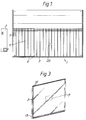
- a typical system comprises a display device 1, a vending machine 2 and multiplicity of advertising cards 3 and card holders 4.
- the display panel 1 is equipped with a transparent front panel 5 having integrally formed equi-spaced vertical ribs 6 spaced to suit the card holder 4.
- Each rib has small integrally formed projections 7 to form a retaining device in order to keep the card holder 4 at the first location until a further card holder 4 displaces the card into the next position.
- the card holder 4 may be held by others methods, such as magnetic inserts 8 in the card holder 5 attached to ferrous faced rear panel 9, a rubber or other friction or locking material such as Velcro (Trade Mark) faced rear panel 9, springs and or ball catches in the vertical ribs 6.
- the transparent front panel 5 is secured to a rear panel 9 in such a manner as to permit the incorporation of a deflection device 10 at its upper edge and a card extraction system 11 at its lower edge, the whole being equipped with brackets or other anchor pivots 12 to enable it to be secured to a wall or other structure.
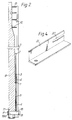
- a card holder 4 is formed by folding a strip of transparent plastics material such as Perspex (Trade Mark) into a very tight "U" form 13 producing a clip like shape with legs 14 which may be sprung open by finger pressure in order to insert a card 3 and which will hold the card 3 firmly in place.
- Perspex Trade Mark
- a deflection device 10 across the entrance to the slots 15 is constructed from a multiplicity of short brush like strips, the fibres of which project inwardly from both front and back of the display panel 1 in such a manner as to be displaced vertically alternately from front and back to form a baffle 16 which will accept stiff card holders 4 but will bend and deflect any flexible materials pushed into the device.
- a card holder retainer system 17 comprising a series of cylindrical pins 18 having a circumferential groove 19 at each end and passing through the transparent panel 5 such that a lockable slide bar 20 at the lower rear face of rear panel 9 can slideably engage the rear groove 19a and by moving a small distance can disengage the groove 19a and allow the pin 18 to be removed forward through the front panel 5 by virtue of its also passing through circular holes 21 in the slide bar 20 thus permitting card holders to be withdrawn from display. Reinsertion of the pins 18 and locking the slide bar into the groove engaging position locks the display system.
- the transparent plate is pivotable about the base of the device.
- FIG. 5 A more sophisticated baffle means is shown in Figures 5 and 6.
- a shutter 22 is biased by springs 23 to close the slot or track for carrying an element information element into the body of the device.
- Pawls 24, 24a engage shutter 22 preventing it from opening.
- the pawls are biased to this position by springs (not shown).
- spring means or counterbalance means can be used.
- both pawls 24, 24a are disengaged from the shutter 22.
- the weight of the element overcomes the biasing means of the shutter which pivots allowing the element to enter the body of the device.
- the apparatus After passage of the element the apparatus returns to the rest position described. If the element is too narrow then both pawls will not be disengaged thereby preventing the shutter from opening. If the element is too light it will not be able to overcome the biasing means also preventing the element from entering the body of the device. It will be remembered that it is preferred that the information element be relatively massive and so many attempts to insert using cards and other authorised information elements will be thwarted.
- a preferred information element is shown in Figure 7. It comprises a box or solid block 25 which may be of transparent plastics material of similar dimensions to a box for compact discs.
- One face 26 carries a card 3 for a message or a slot for insertion of such a card, a business card or a photograph.
- the opposite face may carry a lottery ticket or the like in a slot.
- the information holder may be provided with a cavity 27 or other means for storing a writing instrument.
- Preferably at least part of the mechanism is covered by an opaque panel when the device is in use.
- the display device may also carry other information for example, maps or advertisements for large organisations especially radio or tv stations which generally do not carry "small ads". This information is generally carried on the periphery of the board and not in information holders.
- each site operator is supplied with boards in which the operative width is unique to him thereby avoiding users obtaining information elements from one site operator and using them in another.
- each shutter will generally require at least two pawls.
- the ribs could be a constant distance apart and the pawls movable. Where the shutter is actuated by a magnetic strip only the code need differ.
Landscapes
- Physics & Mathematics (AREA)
- General Physics & Mathematics (AREA)
- Engineering & Computer Science (AREA)
- Theoretical Computer Science (AREA)
- Control Of Vending Devices And Auxiliary Devices For Vending Devices (AREA)
- Indicating And Signalling Devices For Elevators (AREA)
- Illuminated Signs And Luminous Advertising (AREA)
- Devices For Indicating Variable Information By Combining Individual Elements (AREA)
- Circuits Of Receivers In General (AREA)
Claims (5)
- Vorrichtung zur Anzeige von Information, wobei die Vorrichtung eine Anzeigetafel mit lichtdurchlässiger Fläche zur Befestigung an eine Oberfläche umfasst, wobei die Tafel ein Trägermittel zwischen der durchsichtigen Fläche (2) und der Fläche zum Tragen eines festen Informationselements (5) hat, und eine Öffnung (6) zum Einschieben des Elements auf das Trägermittel, dadurch gekennzeichnet, daß die Öffnung mit einer Ablenkplatte versehen ist, (9) zum Beispiel, die elastisch geneigte Elemente umfasst, die den Eingang eines festen Informationselements gestatten, den Eingang eines flexiblen Informationselements aber verhindern.
- Vorrichtung nach Anspruch 1, in der ein Informationselement (5) einen U-förmigen Halter aus durchsichtigem Kunststoffmaterial umfasst, um eine Karte (12) zu empfangen und zu greifen.
- Vorrichtung nach Anspruch 1 oder Anspruch 2, in der das Trägermittel senkrechte Bahnen definiert, die mit einer Vielzahl von elastisch geneigten Ortungsmitteln (4) versehen sind, um eine Informationselement (5) zurückzuhalten, bis es von einem weiteren Informationselement in eine benachbarte Stellung verschoben wird.
- Vorrichtung nach einem der vorhergehenden Ansprüche, in der die Vorrichtung verschliessbare Entfernungsmittel (15,16,17) zum Entfernen eines Elements hat.
- Vorrichtung nach einem der vorhergehenden Ansprüche, die zusätzlich einen Verkaufsautomaten (11) zur Lieferung von Informationselementen umfasst.
Applications Claiming Priority (6)
| Application Number | Priority Date | Filing Date | Title |
|---|---|---|---|
| GB888809763A GB8809763D0 (en) | 1988-04-25 | 1988-04-25 | Pay & display advertising system |
| GB8809763 | 1988-04-25 | ||
| GB888818771A GB8818771D0 (en) | 1988-08-08 | 1988-08-08 | Information display device |
| GB8818771 | 1988-08-08 | ||
| GB8826198 | 1988-11-09 | ||
| GB888826198A GB8826198D0 (en) | 1988-11-09 | 1988-11-09 | Information display device |
Publications (2)
| Publication Number | Publication Date |
|---|---|
| EP0339937A1 EP0339937A1 (de) | 1989-11-02 |
| EP0339937B1 true EP0339937B1 (de) | 1995-01-11 |
Family
ID=27263876
Family Applications (1)
| Application Number | Title | Priority Date | Filing Date |
|---|---|---|---|
| EP89304113A Expired - Lifetime EP0339937B1 (de) | 1988-04-25 | 1989-04-25 | Informationsanzeigevorrichtung |
Country Status (9)
| Country | Link |
|---|---|
| EP (1) | EP0339937B1 (de) |
| JP (1) | JPH03503941A (de) |
| AT (1) | ATE117113T1 (de) |
| AU (1) | AU3558289A (de) |
| DE (1) | DE68920473T2 (de) |
| ES (1) | ES2069579T3 (de) |
| GB (1) | GB2220292B (de) |
| IE (1) | IE66584B1 (de) |
| WO (1) | WO1989010608A1 (de) |
Families Citing this family (2)
| Publication number | Priority date | Publication date | Assignee | Title |
|---|---|---|---|---|
| DE10219379A1 (de) * | 2002-04-30 | 2003-11-20 | Streetvending Ag | Vorrichtung zur automatischen Abgabe eines Produktes |
| CN103824536A (zh) * | 2014-01-23 | 2014-05-28 | 苏州中贸铝业有限公司 | 一种具有燕尾式底座的广告架 |
Family Cites Families (5)
| Publication number | Priority date | Publication date | Assignee | Title |
|---|---|---|---|---|
| US1329568A (en) * | 1914-05-28 | 1920-02-03 | Acme Card System Co | Listing device |
| FR578036A (fr) * | 1924-03-03 | 1924-09-15 | Tableau d'affichage à annonces variables | |
| US2101965A (en) * | 1937-07-16 | 1937-12-14 | Medallic Art Company | Metal panel |
| US2951301A (en) * | 1959-03-23 | 1960-09-06 | Shaw & Slavsky Inc | Identification and claim tag system |
| CH440790A (de) * | 1966-02-28 | 1967-07-31 | Landenberger Eugen | Einrichtung zum Ausstellen von schriftlichen oder bildlichen Anzeigen |
-
1989
- 1989-04-25 ES ES89304113T patent/ES2069579T3/es not_active Expired - Lifetime
- 1989-04-25 AT AT89304113T patent/ATE117113T1/de not_active IP Right Cessation
- 1989-04-25 JP JP1505132A patent/JPH03503941A/ja active Pending
- 1989-04-25 GB GB8909409A patent/GB2220292B/en not_active Expired - Lifetime
- 1989-04-25 AU AU35582/89A patent/AU3558289A/en not_active Abandoned
- 1989-04-25 DE DE68920473T patent/DE68920473T2/de not_active Expired - Fee Related
- 1989-04-25 EP EP89304113A patent/EP0339937B1/de not_active Expired - Lifetime
- 1989-04-25 IE IE135189A patent/IE66584B1/en not_active IP Right Cessation
- 1989-04-25 WO PCT/GB1989/000436 patent/WO1989010608A1/en not_active Ceased
Also Published As
| Publication number | Publication date |
|---|---|
| GB8909409D0 (en) | 1989-06-14 |
| JPH03503941A (ja) | 1991-08-29 |
| IE891351L (en) | 1989-10-25 |
| GB2220292A (en) | 1990-01-04 |
| EP0339937A1 (de) | 1989-11-02 |
| DE68920473T2 (de) | 1995-09-14 |
| IE66584B1 (en) | 1996-01-24 |
| ES2069579T3 (es) | 1995-05-16 |
| WO1989010608A1 (en) | 1989-11-02 |
| GB2220292B (en) | 1992-06-17 |
| ATE117113T1 (de) | 1995-01-15 |
| DE68920473D1 (de) | 1995-02-23 |
| AU3558289A (en) | 1989-11-24 |
Similar Documents
| Publication | Publication Date | Title |
|---|---|---|
| US4598810A (en) | Apparatus and method for vending and accepting return of re-usable articles | |
| EP1131782B1 (de) | Verfahren und vorrichtung zum schutz von durch münzprüfer ausgegebenen gutscheinen von verfälschung | |
| CA2752551C (en) | Printed document including bar code authentication system | |
| US6814518B2 (en) | Secure printer system for gaming devices | |
| US4024379A (en) | Binary system for magnetic card actuation for laundry machines | |
| US20020129527A1 (en) | Card holder | |
| RU2000100347A (ru) | Способ и устройство для идентификации избирателя | |
| GB2395826A (en) | Library checking system | |
| CA2150851C (en) | Electronic transit fare card system | |
| GB2207268A (en) | Game machines | |
| EP0339937B1 (de) | Informationsanzeigevorrichtung | |
| CA1217744A (en) | Article dispensing apparatus and method having remote purchase initiation and delivery stations | |
| CA1330487C (en) | Information display device | |
| US3478316A (en) | Inventory control system | |
| US8245905B2 (en) | Locking ballot receptacle | |
| GB2199287A (en) | Displayable parking ticket | |
| US3274718A (en) | Information display panel | |
| CA2340828C (en) | Card holder | |
| JPH0388095A (ja) | ロッカーの開閉制御方法 | |
| JPH0630113B2 (ja) | 磁気カ−ド利用システムにおける保安方法 | |
| JP2002319005A (ja) | 情報記録カード発券装置,情報記録カード回収装置 | |
| JPH07175949A (ja) | 整理券発行回収システム、整理券発行器、運賃箱および整理券 | |
| JPH10240972A (ja) | 自動券売機 | |
| JPH0869560A (ja) | プリペードカード発券・販売機及び運用方式 | |
| JPS63173271A (ja) | 磁気カ−ド利用システムにおける保安方式 |
Legal Events
| Date | Code | Title | Description |
|---|---|---|---|
| PUAI | Public reference made under article 153(3) epc to a published international application that has entered the european phase |
Free format text: ORIGINAL CODE: 0009012 |
|
| AK | Designated contracting states |
Kind code of ref document: A1 Designated state(s): AT BE CH DE ES FR GB GR IT LI LU NL SE |
|
| 17P | Request for examination filed |
Effective date: 19900427 |
|
| 17Q | First examination report despatched |
Effective date: 19930524 |
|
| RBV | Designated contracting states (corrected) |
Designated state(s): AT BE CH DE ES FR GR IT LI LU NL SE |
|
| RAP1 | Party data changed (applicant data changed or rights of an application transferred) |
Owner name: BURNARD, CRAIG NIGEL Owner name: FARREN, NICHOLAS ERNEST |
|
| GRAA | (expected) grant |
Free format text: ORIGINAL CODE: 0009210 |
|
| AK | Designated contracting states |
Kind code of ref document: B1 Designated state(s): AT BE CH DE ES FR GR IT LI LU NL SE |
|
| PG25 | Lapsed in a contracting state [announced via postgrant information from national office to epo] |
Ref country code: NL Effective date: 19950111 Ref country code: LI Effective date: 19950111 Ref country code: GR Free format text: LAPSE BECAUSE OF FAILURE TO SUBMIT A TRANSLATION OF THE DESCRIPTION OR TO PAY THE FEE WITHIN THE PRESCRIBED TIME-LIMIT Effective date: 19950111 Ref country code: CH Effective date: 19950111 Ref country code: BE Effective date: 19950111 Ref country code: AT Effective date: 19950111 |
|
| REF | Corresponds to: |
Ref document number: 117113 Country of ref document: AT Date of ref document: 19950115 Kind code of ref document: T |
|
| REF | Corresponds to: |
Ref document number: 68920473 Country of ref document: DE Date of ref document: 19950223 |
|
| ITF | It: translation for a ep patent filed | ||
| PG25 | Lapsed in a contracting state [announced via postgrant information from national office to epo] |
Ref country code: SE Effective date: 19950411 |
|
| REG | Reference to a national code |
Ref country code: CH Ref legal event code: PL |
|
| PG25 | Lapsed in a contracting state [announced via postgrant information from national office to epo] |
Ref country code: LU Free format text: LAPSE BECAUSE OF NON-PAYMENT OF DUE FEES Effective date: 19950430 |
|
| ET | Fr: translation filed | ||
| REG | Reference to a national code |
Ref country code: ES Ref legal event code: FG2A Ref document number: 2069579 Country of ref document: ES Kind code of ref document: T3 |
|
| NLV1 | Nl: lapsed or annulled due to failure to fulfill the requirements of art. 29p and 29m of the patents act | ||
| PLBE | No opposition filed within time limit |
Free format text: ORIGINAL CODE: 0009261 |
|
| STAA | Information on the status of an ep patent application or granted ep patent |
Free format text: STATUS: NO OPPOSITION FILED WITHIN TIME LIMIT |
|
| 26N | No opposition filed | ||
| PGFP | Annual fee paid to national office [announced via postgrant information from national office to epo] |
Ref country code: FR Payment date: 20000425 Year of fee payment: 12 |
|
| PGFP | Annual fee paid to national office [announced via postgrant information from national office to epo] |
Ref country code: ES Payment date: 20000508 Year of fee payment: 12 |
|
| PGFP | Annual fee paid to national office [announced via postgrant information from national office to epo] |
Ref country code: DE Payment date: 20001004 Year of fee payment: 12 |
|
| PG25 | Lapsed in a contracting state [announced via postgrant information from national office to epo] |
Ref country code: ES Free format text: LAPSE BECAUSE OF NON-PAYMENT OF DUE FEES Effective date: 20010426 |
|
| PG25 | Lapsed in a contracting state [announced via postgrant information from national office to epo] |
Ref country code: FR Free format text: THE PATENT HAS BEEN ANNULLED BY A DECISION OF A NATIONAL AUTHORITY Effective date: 20010430 |
|
| PG25 | Lapsed in a contracting state [announced via postgrant information from national office to epo] |
Ref country code: DE Free format text: LAPSE BECAUSE OF NON-PAYMENT OF DUE FEES Effective date: 20020201 |
|
| REG | Reference to a national code |
Ref country code: FR Ref legal event code: ST |
|
| REG | Reference to a national code |
Ref country code: ES Ref legal event code: FD2A Effective date: 20030303 |
|
| PG25 | Lapsed in a contracting state [announced via postgrant information from national office to epo] |
Ref country code: IT Free format text: LAPSE BECAUSE OF NON-PAYMENT OF DUE FEES;WARNING: LAPSES OF ITALIAN PATENTS WITH EFFECTIVE DATE BEFORE 2007 MAY HAVE OCCURRED AT ANY TIME BEFORE 2007. THE CORRECT EFFECTIVE DATE MAY BE DIFFERENT FROM THE ONE RECORDED. Effective date: 20050425 |