EP0338874B1 - Explosivgeschoss mit Ausstreuungseffekt - Google Patents
Explosivgeschoss mit Ausstreuungseffekt Download PDFInfo
- Publication number
- EP0338874B1 EP0338874B1 EP89400806A EP89400806A EP0338874B1 EP 0338874 B1 EP0338874 B1 EP 0338874B1 EP 89400806 A EP89400806 A EP 89400806A EP 89400806 A EP89400806 A EP 89400806A EP 0338874 B1 EP0338874 B1 EP 0338874B1
- Authority
- EP
- European Patent Office
- Prior art keywords
- projectile
- payload
- sections
- casing
- fact
- Prior art date
- Legal status (The legal status is an assumption and is not a legal conclusion. Google has not performed a legal analysis and makes no representation as to the accuracy of the status listed.)
- Expired - Lifetime
Links
- 239000002360 explosive Substances 0.000 title abstract description 38
- 238000004880 explosion Methods 0.000 title description 2
- 239000000463 material Substances 0.000 claims abstract description 19
- 239000002184 metal Substances 0.000 claims abstract description 15
- 239000012634 fragment Substances 0.000 claims description 25
- 230000003247 decreasing effect Effects 0.000 claims description 9
- 239000007787 solid Substances 0.000 claims description 8
- 230000035939 shock Effects 0.000 claims description 6
- 238000013467 fragmentation Methods 0.000 claims description 4
- 238000006062 fragmentation reaction Methods 0.000 claims description 4
- 230000007423 decrease Effects 0.000 claims description 3
- 239000008188 pellet Substances 0.000 claims description 2
- 238000011144 upstream manufacturing Methods 0.000 abstract description 8
- 238000013016 damping Methods 0.000 abstract description 6
- 238000010304 firing Methods 0.000 abstract description 2
- 239000013598 vector Substances 0.000 description 17
- 238000009826 distribution Methods 0.000 description 8
- 206010041662 Splinter Diseases 0.000 description 7
- 230000005540 biological transmission Effects 0.000 description 5
- 238000005474 detonation Methods 0.000 description 5
- 230000000977 initiatory effect Effects 0.000 description 5
- 239000007921 spray Substances 0.000 description 4
- 235000012431 wafers Nutrition 0.000 description 4
- 239000006185 dispersion Substances 0.000 description 3
- 230000037452 priming Effects 0.000 description 2
- 229910000831 Steel Inorganic materials 0.000 description 1
- 240000008042 Zea mays Species 0.000 description 1
- 239000011358 absorbing material Substances 0.000 description 1
- 238000004364 calculation method Methods 0.000 description 1
- 230000006835 compression Effects 0.000 description 1
- 238000007906 compression Methods 0.000 description 1
- 230000001143 conditioned effect Effects 0.000 description 1
- 230000000694 effects Effects 0.000 description 1
- 230000005484 gravity Effects 0.000 description 1
- 238000000034 method Methods 0.000 description 1
- 239000000203 mixture Substances 0.000 description 1
- 230000000149 penetrating effect Effects 0.000 description 1
- 239000011359 shock absorbing material Substances 0.000 description 1
- 238000004088 simulation Methods 0.000 description 1
- 230000003068 static effect Effects 0.000 description 1
- 239000010959 steel Substances 0.000 description 1
- 238000009827 uniform distribution Methods 0.000 description 1
Images



Classifications
-
- F—MECHANICAL ENGINEERING; LIGHTING; HEATING; WEAPONS; BLASTING
- F42—AMMUNITION; BLASTING
- F42B—EXPLOSIVE CHARGES, e.g. FOR BLASTING, FIREWORKS, AMMUNITION
- F42B12/00—Projectiles, missiles or mines characterised by the warhead, the intended effect, or the material
- F42B12/02—Projectiles, missiles or mines characterised by the warhead, the intended effect, or the material characterised by the warhead or the intended effect
- F42B12/20—Projectiles, missiles or mines characterised by the warhead, the intended effect, or the material characterised by the warhead or the intended effect of high-explosive type
- F42B12/201—Projectiles, missiles or mines characterised by the warhead, the intended effect, or the material characterised by the warhead or the intended effect of high-explosive type characterised by target class
- F42B12/204—Projectiles, missiles or mines characterised by the warhead, the intended effect, or the material characterised by the warhead or the intended effect of high-explosive type characterised by target class for attacking structures, e.g. specific buildings or fortifications, ships or vehicles
-
- F—MECHANICAL ENGINEERING; LIGHTING; HEATING; WEAPONS; BLASTING
- F42—AMMUNITION; BLASTING
- F42B—EXPLOSIVE CHARGES, e.g. FOR BLASTING, FIREWORKS, AMMUNITION
- F42B12/00—Projectiles, missiles or mines characterised by the warhead, the intended effect, or the material
- F42B12/02—Projectiles, missiles or mines characterised by the warhead, the intended effect, or the material characterised by the warhead or the intended effect
- F42B12/20—Projectiles, missiles or mines characterised by the warhead, the intended effect, or the material characterised by the warhead or the intended effect of high-explosive type
- F42B12/208—Projectiles, missiles or mines characterised by the warhead, the intended effect, or the material characterised by the warhead or the intended effect of high-explosive type characterised by a plurality of charges within a single high explosive warhead
Definitions
- the technical sector of the present invention is that of explosive projectiles comprising a fragmentation envelope and an explosive charge, generating splinters during the explosion.
- US-A-3498224 describes a military head in which a number of rows of metal cubes constituting preformed shards are arranged between the explosive and the envelope. Such an arrangement makes it possible to obtain a widening of the sheaf of splinters but it is necessary for this to vary the thickness of metal along the axis of the military head therefore to design a complete projectile (envelope and loading) with special geometric characteristics.
- Patent FR-A-2599134 describes a military head intended to destroy a warhead penetrating at high speed into the atmosphere and which can generate, as desired, two different types of splinter distribution from two thicknesses of explosive separated by a space free. This charge does not aim to communicate significant kinetic energy to the fragments but rather to position almost immobile fragments on the trajectory of the target warhead. This document illustrates the preamble of claim 1.
- the object of the present invention is therefore to propose a projectile generating a spray of splinters covering an area greater than that covered by known projectiles, which has the consequence of giving it greater efficiency.
- the invention also provides a projectile generating a focused burst of shrapnel.
- the subject of the invention is therefore a projectile generating a burst of splinters by controlled operation on a trajectory during a tense shot, comprising an explosive charge contained in a metal envelope and comprising means for varying along its longitudinal axis x'x the ratio R of the radial thicknesses (e) of the explosive charge and (E) of the metallic envelope containing said charge, so as to modulate along the longitudinal axis the speed of the fragments, projectile characterized in that the variation of the ratio R is obtained by modulating the radial thickness (e) of the explosive charge, an explosive free space being filled with an inert shock wave damping material.
- the ratio R can be increasing from upstream to downstream, discontinuously according to several radial loading thicknesses or continuously to ensure dispersion of the chips.
- the load may comprise a first slice of thickness equal to the internal diameter of the envelope, four tubular slices of increasing radial thickness towards the base, a free space being provided within these slices, and a solid slice disposed at the level of the base, of thickness equal to the internal diameter of the envelope.
- the load may consist of a first section of diameter equal to the internal diameter of the envelope and of four full sections of increasing thickness towards the base, a free space being provided between the metal casing and these four sections.
- the ratio R can be decreasing from upstream to downstream, discontinuously according to several radial loading thicknesses or continuous to ensure focusing of the fragments.
- the load can comprise a first section of diameter equal to the internal diameter of the envelope, and four tubular sections of decreasing radial thickness towards the base, a free space being provided within these sections.
- the load can comprise a first section of diameter equal to the internal diameter of the envelope, and four solid sections of decreasing thickness towards the base, a free space being provided between the metal casing and these four sections.
- An inert shock-absorbing material can be interposed in the free space within the tubular sections.
- An inert shock wave absorbing material can be interposed in the free space between the envelope and the full wafers.
- Loading can be achieved by stacking tablets.
- An advantage of the present invention lies in the implementation of simple means for varying the speed of the fragments relative to the projectile, and it is surprisingly found that a small variation in this speed causes a variation in the resulting speed of the fragments relative to on the ground and therefore a great dispersion of the sheaf.
- FIG. 1 shows the combination of the static velocity vectors measured when the projectile is stopped in order to illustrate the zones of effectiveness of the fragments.
- the minimum speeds of the flakes V m , the maximum speeds of the flakes V M are measured for a known projectile of 35 mm caliber and these same speeds V ′ m and V ′ M for a projectile according to the invention of the same caliber.
- the speeds V M and V m of the fragments are communicated by the detonation of the explosive and are measured in a reference frame linked to the projectile.
- the speed V R of the projectile is identical in both cases since it is the flight speed of the latter and it is measured relative to the ground.
- the combination of the burst speed vectors with the flight speed delimits an area of efficiency on the ground.
- the combination of the velocity vectors V R and V M or V ′ M gives a resulting vector whose intersection with the ground gives the point A.
- the combination of the vectors V R and V m gives a resulting vector whose intersection with the ground gives the point B.
- the points A and B then delimit the zone P1 of effectiveness of the known projectile whose width is of the order of 3 m for a projectile initiated at 10 meters from the ground.
- the combination of the vectors V R and V ′ m gives a resulting vector whose intersection with the ground gives the point C.
- the points A and C then delimit the zone P2 of effectiveness of the projectile according to the invention which is of the order of 5 m. It can be seen that the invention makes it possible to enlarge the zone of effectiveness of the projectile.
- the vectors representing the speed of the bursts relative to the projectile are not normal to the lateral surface of the latter, but are inclined in the direction of propagation of the detonation wave inside the explosive charge .
- FIG 2 there is shown a partial section of a projectile of axis X′X where we see the explosive 1 thick (e) and the metal casing 2 thick (E).
- the thickness of the explosive will more generally be defined as being the half-difference of the external and internal diameters (when the latter exists) of the section of explosive considered. In Figure 2, it is a full slice.
- Vx F (NatExpl, Dexpl, Denv, x, R) It is also known that the speed Vx will vary like the ratio R, so that a low value of this ratio will cause a reduced speed and vice versa.
- the ratio R is varied.
- the invention proposes to modulate the speeds of the flakes along the longitudinal axis of the projectile by playing on the values of the ratio R along this same axis.
- the characteristics desired for the projectile efficiency, therefore width of area covered by the fragments at a given operating height
- it will be possible to define a minimum speed of the fragments (the maximum speed being that corresponding to the maximum loading of the 'envelope).
- Figure 1 showed the burst velocity vectors with a common origin located at the point of operation. In reality, for a given section of the projectile, the speed vectors have their origin at the level of said section.
- FIGS. 3 and 4 show more precisely the distribution of the speed vectors along the envelope of the projectile, always in the case of a priming by warhead rocket (vectors inclined downstream of the projectile).
- FIG. 3 represents a projectile in which the burst velocities have an increasing value from upstream to downstream (projectile according to the variant embodiments of FIGS. 5 and 6), this value being able to increase continuously or else in stages.
- the result is a scattering of the chips.
- FIG. 4 represents a projectile in which the burst velocities have a decreasing value from upstream to downstream (projectile according to the variant embodiments of FIGS. 7 and 8).
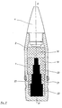
- a projectile 3 which can be a medium caliber shell, of longitudinal axis x′x. It includes a head rocket 4 and a metal casing 2 made of steel.
- the envelope contains the explosive charge 1 consisting of six 5-10 sections of explosive.
- the envelope 1 can be weakened beforehand according to the method taught in the French patent cited above.
- the maximum thickness of the load corresponds to the case of full load.
- the minimum thickness is conditioned either by the calculation of the effectiveness of the projectile, or by the value of the critical thickness of the explosive allowing the transmission of the shock wave.
- the ratio R is modulated continuously or discontinuously. In the invention, examples have been described for illustrative purposes in which the ratio R is discontinuous.
- the wafer 5 has a thickness equal to the internal diameter of the envelope 1 and the other four wafers 6 to 9 are in the form of tubular elements of increasing thickness towards the base of the projectile. The heights of these different sections are determined so as to obtain a uniform distribution over the area to be covered.
- a solid wafer 10 is placed at the level of the projectile base.
- the number and the height of the sections is a function of the progressiveness which one wishes to adopt between the speeds V m and V M.
- the ratio R of the thickness of the load 1 and of the casing 2 is varied increasing along the axis x′x towards the base.
- the speed of the flakes generated at each slice is therefore increasing in the same direction, which makes it possible to distribute the flakes more widely over the upstream and downstream zones mentioned above.
- a module 11 is placed in inert material, both in terms of detonation and that of fragmentation. Its density is equivalent to that of the explosive.
- a pulverulent or compressed material similar to the ballast used in exercise shells is used.
- FIG 5 there is shown a load 1 consisting of a cast block; one could use a load consisting of a stack of tablets corresponding to sections 5-10. These can be obtained by compression.
- a 35 mm explosive projectile according to the state of the art comprising a prefragmented envelope, for example by electronic bombardment, (see French patent cited above), is initiated at a distance from the ground of the order of 10 meters while being animated with a speed of the order of 910 m / s.
- the fragments are then distributed in a global zone, along the axis of fire, of the order of 3.20 meters.
- the average density of flakes, along the axis of fire, is then substantially 5.41.
- FIG. 6 there is shown an alternative embodiment of the load 1.
- This load 1 consists of five sections of explosive 12-16.
- the thickness of these slices which are in the form of solid elements aligned on the axis x′x, increases towards the pellet.
- a damping material 17 is placed between the casing 2 and the charge 1.
- the role of this material is to absorb part of the energy of the explosive, which makes it possible to obtain a reduced burst speed with a greater thickness of explosive.
- This solution makes it possible to use the invention in the case of an explosive with a large critical thickness for the transmission of the detonation or when it is impossible to achieve a charge of small thickness. A dispersion of the same order as that of the projectile according to FIG. 5 is ensured.
- the load 1 comprises five sections 18-22 all being in the form of cylindrical elements, stacked on the axis x′x. Section 18 is full while sections 19-22 are annular. An inert material 23 is placed in the free space within the sections and its role is to dampen the transmission of the shock wave as it passes. This damping increases with the thickness of the material 23 when one goes towards the base. In this embodiment, the variation of the ratio R results in focusing of the flakes.
- FIG. 8 another alternative embodiment is shown showing five sections of explosive.
- the section 24 is identical to the section 18 of the previous embodiment, while the sections 25-28 are formed by solid cylindrical elements aligned on the axis x′x.
- a material 29 can be provided in the form of a single piece as shown on the left part of the figure when using a single piece load.
- We can also proceed by superimposing tablets rimmed with inert materials as shown in the right part of the figure.
- a focusing of the fragments is obtained.
- the number and the height of each section is a function of the progressiveness which it is desired to adopt between the speeds V m and V M.
Landscapes
- Engineering & Computer Science (AREA)
- Chemical & Material Sciences (AREA)
- Combustion & Propulsion (AREA)
- General Engineering & Computer Science (AREA)
- Drilling And Exploitation, And Mining Machines And Methods (AREA)
- Aiming, Guidance, Guns With A Light Source, Armor, Camouflage, And Targets (AREA)
- Agricultural Chemicals And Associated Chemicals (AREA)
- Chair Legs, Seat Parts, And Backrests (AREA)
- Engine Equipment That Uses Special Cycles (AREA)
- Nozzles (AREA)
Claims (10)
- Explosivgeschoß mit Ausstreuungseffekt, mit steuerbarer Auslösung auf einer Flugbahn während eines Dauerbeschusses, bestehend aus einer Sprengladung (1) in einer Metallhülle (2), das über Mittel verfügt, mit denen das Verhältnis R der radialen Schichtdicken (e) der Sprengladung (1) und (E) der Metallhülle (2), die die erwähnte Ladung umschließt, entlang der Längsachse des Geschosses x'x variiert werden kann, um die Splittergeschwindigkeit entlang der Längsachse zu modulieren, wobei dieses Geschoß dadurch gekennzeichnet ist, daß die Variation des Verhältnisses R durch eine Modulation der radialen Schichtdicke (e) der Sprengladung (1) erzielt wird, und ein sprengstoffreier Zwischenraum von einem inaktiven Material (11, 17, 23, 29) ausgefüllt wird, das die Druckwelle abschwächen soll.
- Geschoß gemäß Patentanspruch 1, dadurch gekennzeichnet, daß das Verhältnis R vom vorderen zum hinteren Bereich hin je nach den verschiedenen radialen schichtdicken der Ladung diskontinuierlich oder kontinuierlich zunimmt, um eine Streuwirkung der Splitter zu erzielen.
- Geschoß gemäß Patentanspruch 2, dadurch gekennzeichnet, daß die Ladung aus einem ersten Abschnitt (5), dessen Dicke dem Innendurchmesser der Hülle (2) entspricht, sowie vier röhrenförmigen Abschnitten (6-9) besteht, deren radiale Dicke zum Geschoßboden hin zunimmt, mit einem Zwischenraum im Innern dieser Abschnitte (6-9), der mit einem inaktiven Material gefüllt ist, sowie einem Abschnitt (10) auf der Höhe des Geschoßbodens, dessen Dicke dem Innendurchmesser der Hülle (2) entspricht.
- Geschoß gemäß Patentanspruch 2, dadurch gekennzeichnet, daß die Ladung (1) aus einem ersten Abschnitt (12), dessen Durchmesser dem Innendurchmesser der Hülle (2) entspricht, sowie vier vollen Abschnitten (13-16) besteht, deren Dicke zum Geschoßboden hin zunimmt, wobei sich zwischen der Metallhülle und diesen vier Abschnitten ein Zwischenraum befindet, der mit einem inaktiven Material gefüllt ist.
- Geschoß gemäß Patentanspruch 1, dadurch gekennzeichnet, daß das Verhältnis R vom vorderen zum hinteren Bereich hin je nach den verschiedenen radialen Schichtdicken der Ladung diskontinuierlich oder kontinuierlich abnimmt, um eine Fokalisierung der Splitter zu erreichen.
- Geschoß gemäß Patentanspruch 5, dadurch gekennzeichnet, daß die Ladung aus einem ersten Abschnitt (18), dessen Durchmesser dem Innendurchmesser der Hülle (2) entspricht, sowie vier röhrenförmigen Abschnitten (19-22) besteht, deren radiale Dicke zum Geschoßboden hin abnimmt, mit einem Zwischenraum im Innern dieser Abschnitte (19-22), der mit dem inaktiven Material gefüllt ist.
- Geschoß gemäß Patentanspruch 5, dadurch gekennzeichnet, daß die Ladung (1) aus einem ersten Abschnitt (24), dessen Durchmesser dem Innendurchmesser der Hülle (2) entspricht, sowie vier vollen Abschnitten (25-28) besteht, deren Dicke zum Geschoßboden hin abnimmt, wobei sich zwischen der Metallhülle (2) und diesen vier Abschnitten ein Zwischenraum befindet, der mit einem inaktiven Material gefüllt ist.
- Geschoß nach einem der Patentansprüche 3 bis 7, dadurch gekennzeichnet, daß das inaktive Material (11,23,17,29), das sich in dem Zwischenraum im Innern dieser röhrenförmigen Abschnitte (6-9,19-22) bzw. zwischen der Hülle (2) und den vollen Abschnitten (13-16,25-28) befindet, die Druckwelle abschwächt.
- Geschoß nach einem der Patentansprüche 3 bis 7, dadurch gekennzeichnet, daß das inaktive Material die gleiche Dichte aufweist wie der Sprengstoff.
- Geschoß nach einem der Patentansprüche 3 bis 9, dadurch gekennzeichnet, daß die Ladung aus gestapelten Zündpillen besteht.
Priority Applications (1)
| Application Number | Priority Date | Filing Date | Title |
|---|---|---|---|
| AT89400806T ATE100189T1 (de) | 1988-03-31 | 1989-03-22 | Explosivgeschoss mit ausstreuungseffekt. |
Applications Claiming Priority (2)
| Application Number | Priority Date | Filing Date | Title |
|---|---|---|---|
| FR8804256 | 1988-03-31 | ||
| FR8804256A FR2629582B1 (fr) | 1988-03-31 | 1988-03-31 | Projectile explosif engendrant une gerbe d'eclats |
Publications (2)
| Publication Number | Publication Date |
|---|---|
| EP0338874A1 EP0338874A1 (de) | 1989-10-25 |
| EP0338874B1 true EP0338874B1 (de) | 1994-01-12 |
Family
ID=9364827
Family Applications (1)
| Application Number | Title | Priority Date | Filing Date |
|---|---|---|---|
| EP89400806A Expired - Lifetime EP0338874B1 (de) | 1988-03-31 | 1989-03-22 | Explosivgeschoss mit Ausstreuungseffekt |
Country Status (4)
| Country | Link |
|---|---|
| EP (1) | EP0338874B1 (de) |
| AT (1) | ATE100189T1 (de) |
| DE (1) | DE68912182D1 (de) |
| FR (1) | FR2629582B1 (de) |
Families Citing this family (6)
| Publication number | Priority date | Publication date | Assignee | Title |
|---|---|---|---|---|
| US5535679A (en) * | 1994-12-20 | 1996-07-16 | Loral Vought Systems Corporation | Low velocity radial deployment with predetermined pattern |
| US5691502A (en) * | 1995-06-05 | 1997-11-25 | Lockheed Martin Vought Systems Corp. | Low velocity radial deployment with predeterminded pattern |
| RU2176378C1 (ru) * | 2000-06-27 | 2001-11-27 | Государственное унитарное предприятие "Конструкторское бюро приборостроения" | Реактивный снаряд |
| DE50109825D1 (de) * | 2001-11-28 | 2006-06-22 | Futurtec Ag Rotkreuz | Geschosse hoher Penetrations- und Lateralwirkung mit integrierter Zerlegungseinrichtung |
| GB0904929D0 (en) * | 2009-03-23 | 2009-05-06 | Qinetiq Ltd | Novel munition |
| DE102014019202A1 (de) | 2014-12-19 | 2016-06-23 | Diehl Bgt Defence Gmbh & Co. Kg | Geschoss |
Family Cites Families (5)
| Publication number | Priority date | Publication date | Assignee | Title |
|---|---|---|---|---|
| LU29471A1 (de) * | 1949-03-29 | |||
| US3498224A (en) * | 1968-10-04 | 1970-03-03 | Us Navy | Fragmentation warhead having circumferential layers of cubical fragments |
| US4351239A (en) * | 1975-02-28 | 1982-09-28 | The United States Of America As Represented By The Secretary Of The Navy | Warhead, incendiary |
| US4351240A (en) * | 1975-02-28 | 1982-09-28 | The United States Of America As Represented By The Secretary Of The Navy | Incendiary fragmentary warhead |
| FR2599134B1 (fr) * | 1986-05-23 | 1988-08-26 | Matra | Tete militaire pour engin |
-
1988
- 1988-03-31 FR FR8804256A patent/FR2629582B1/fr not_active Expired - Fee Related
-
1989
- 1989-03-22 DE DE89400806T patent/DE68912182D1/de not_active Expired - Lifetime
- 1989-03-22 AT AT89400806T patent/ATE100189T1/de active
- 1989-03-22 EP EP89400806A patent/EP0338874B1/de not_active Expired - Lifetime
Also Published As
| Publication number | Publication date |
|---|---|
| FR2629582A1 (fr) | 1989-10-06 |
| FR2629582B1 (fr) | 1993-06-04 |
| ATE100189T1 (de) | 1994-01-15 |
| EP0338874A1 (de) | 1989-10-25 |
| DE68912182D1 (de) | 1994-02-24 |
Similar Documents
| Publication | Publication Date | Title |
|---|---|---|
| EP0221218B1 (de) | Sprengkopf mit hintereinanderliegenden Hohlladungen | |
| EP3102906B1 (de) | Hohlladung und verwendung zur trennung von zwei stockwerken eines luftfahrtfahrzeugs oder zur neutralisierung davon | |
| EP0438343B1 (de) | Penetratormunition für Ziele mit hohem mechanischem Widerstand | |
| EP0800054B1 (de) | Geschoss dessen Sprengladung durch einen Zielanzeiger ausgelöst wird | |
| FR2599134A1 (fr) | Tete militaire pour engin | |
| FR2514123A1 (fr) | Perfectionnements apportes aux charges militaires agissant contre des cibles en vol ou au sol | |
| EP0338874A1 (de) | Explosivgeschoss mit Ausstreuungseffekt | |
| EP0437992A1 (de) | Sprengladung zum Bilden mehrerer Bolzen und/oder Stacheln | |
| EP0329530B1 (de) | Verfahren zum Hervorrufen eines mit Stabilisierungsflossen versehenen Stachels und seine Anwendung in einem Gefechtskopf | |
| FR2561376A1 (fr) | Engin explosif a fragmentation | |
| FR3070484A1 (fr) | Prefragmentation d'une ogive | |
| EP0395520A1 (de) | Mit einer Ausstossvorrichtung für Submunitionen versehenes Trägergeschoss | |
| EP0138640A1 (de) | Explosive Ladung für militärische Verwendung | |
| EP1521053B1 (de) | Anti-Bunker Munition | |
| EP1521052A1 (de) | Panzergeschoss | |
| FR2736424A1 (fr) | Tete militaire a charge formee | |
| FR2669722A1 (fr) | Systeme d'arme agissant par attaque plongeante sur l'objectif. | |
| FR2552871A1 (fr) | Projectile antichar agissant en vitesse defilante | |
| FR2704052A1 (fr) | Charge formée multiamorçable. | |
| EP1099926B1 (de) | Explosiver Gefechtskopf mit zwei Betriebsarten, der gegen konventionelle Ziele und gegen taktische ballistische Flugkörper verwendet werden kann | |
| EP0193427B1 (de) | Gefechtskopf mit hintereinanderliegenden Hohlladungen | |
| FR2622966A1 (fr) | Dispositif de stabilisation gyroscopique pour un organe de manoeuvre de projectile | |
| FR2992408A1 (fr) | Tete militaire a projection de noyaux | |
| CH651382A5 (fr) | Charge creuse. | |
| EP3633313B1 (de) | Hülse für munition und munition, die eine solche hülse umfasst |
Legal Events
| Date | Code | Title | Description |
|---|---|---|---|
| PUAI | Public reference made under article 153(3) epc to a published international application that has entered the european phase |
Free format text: ORIGINAL CODE: 0009012 |
|
| 17P | Request for examination filed |
Effective date: 19890330 |
|
| AK | Designated contracting states |
Kind code of ref document: A1 Designated state(s): AT BE CH DE ES GB GR IT LI NL SE |
|
| RAP1 | Party data changed (applicant data changed or rights of an application transferred) |
Owner name: GIAT INDUSTRIES |
|
| 17Q | First examination report despatched |
Effective date: 19920114 |
|
| GRAA | (expected) grant |
Free format text: ORIGINAL CODE: 0009210 |
|
| AK | Designated contracting states |
Kind code of ref document: B1 Designated state(s): AT BE CH DE ES GB GR IT LI NL SE |
|
| PG25 | Lapsed in a contracting state [announced via postgrant information from national office to epo] |
Ref country code: IT Free format text: LAPSE BECAUSE OF FAILURE TO SUBMIT A TRANSLATION OF THE DESCRIPTION OR TO PAY THE FEE WITHIN THE PRE;WARNING: LAPSES OF ITALIAN PATENTS WITH EFFECTIVE DATE BEFORE 2007 MAY HAVE OCCURRED AT ANY TIME BEFORE 2007. THE CORRECT EFFECTIVE DATE MAY BE DIFFERENT FROM THE ONE RECORDED.SCRIBED TIME-LIMIT Effective date: 19940112 Ref country code: NL Effective date: 19940112 Ref country code: GB Effective date: 19940112 Ref country code: SE Effective date: 19940112 Ref country code: AT Effective date: 19940112 Ref country code: GR Free format text: LAPSE BECAUSE OF FAILURE TO SUBMIT A TRANSLATION OF THE DESCRIPTION OR TO PAY THE FEE WITHIN THE PRESCRIBED TIME-LIMIT Effective date: 19940112 Ref country code: ES Free format text: THE PATENT HAS BEEN ANNULLED BY A DECISION OF A NATIONAL AUTHORITY Effective date: 19940112 Ref country code: DE Effective date: 19940112 |
|
| REF | Corresponds to: |
Ref document number: 100189 Country of ref document: AT Date of ref document: 19940115 Kind code of ref document: T |
|
| REF | Corresponds to: |
Ref document number: 68912182 Country of ref document: DE Date of ref document: 19940224 |
|
| PG25 | Lapsed in a contracting state [announced via postgrant information from national office to epo] |
Ref country code: LI Effective date: 19940331 Ref country code: BE Effective date: 19940331 Ref country code: CH Effective date: 19940331 |
|
| NLV1 | Nl: lapsed or annulled due to failure to fulfill the requirements of art. 29p and 29m of the patents act | ||
| GBV | Gb: ep patent (uk) treated as always having been void in accordance with gb section 77(7)/1977 [no translation filed] |
Effective date: 19940112 |
|
| BERE | Be: lapsed |
Owner name: GIAT INDUSTRIES Effective date: 19940331 |
|
| PLBE | No opposition filed within time limit |
Free format text: ORIGINAL CODE: 0009261 |
|
| STAA | Information on the status of an ep patent application or granted ep patent |
Free format text: STATUS: NO OPPOSITION FILED WITHIN TIME LIMIT |
|
| REG | Reference to a national code |
Ref country code: CH Ref legal event code: PL |
|
| 26N | No opposition filed |