EP0338722A2 - Schere für Schuhzwickmaschine - Google Patents
Schere für Schuhzwickmaschine Download PDFInfo
- Publication number
- EP0338722A2 EP0338722A2 EP89303648A EP89303648A EP0338722A2 EP 0338722 A2 EP0338722 A2 EP 0338722A2 EP 89303648 A EP89303648 A EP 89303648A EP 89303648 A EP89303648 A EP 89303648A EP 0338722 A2 EP0338722 A2 EP 0338722A2
- Authority
- EP
- European Patent Office
- Prior art keywords
- wiper
- plate
- shoe
- wiper plate
- movement
- Prior art date
- Legal status (The legal status is an assumption and is not a legal conclusion. Google has not performed a legal analysis and makes no representation as to the accuracy of the status listed.)
- Granted
Links
- 230000002045 lasting effect Effects 0.000 title claims abstract description 46
- 239000000853 adhesive Substances 0.000 claims abstract description 36
- 230000001070 adhesive effect Effects 0.000 claims abstract description 36
- 230000033001 locomotion Effects 0.000 claims description 59
- 210000000080 chela (arthropods) Anatomy 0.000 claims description 9
- 230000000694 effects Effects 0.000 claims description 5
- 230000004044 response Effects 0.000 claims description 5
- 230000008933 bodily movement Effects 0.000 claims description 3
- 210000003371 toe Anatomy 0.000 description 41
- 239000000155 melt Substances 0.000 description 8
- 230000000712 assembly Effects 0.000 description 7
- 238000000429 assembly Methods 0.000 description 7
- 239000000969 carrier Substances 0.000 description 6
- 238000010276 construction Methods 0.000 description 2
- 206010013710 Drug interaction Diseases 0.000 description 1
- 238000006073 displacement reaction Methods 0.000 description 1
- 230000003993 interaction Effects 0.000 description 1
- 230000013011 mating Effects 0.000 description 1
- 239000002184 metal Substances 0.000 description 1
- 239000007787 solid Substances 0.000 description 1
- 125000006850 spacer group Chemical group 0.000 description 1
Images


Classifications
-
- A—HUMAN NECESSITIES
- A43—FOOTWEAR
- A43D—MACHINES, TOOLS, EQUIPMENT OR METHODS FOR MANUFACTURING OR REPAIRING FOOTWEAR
- A43D23/00—Single parts for pulling-over or lasting machines
- A43D23/02—Wipers; Sole-pressers; Last-supports; Pincers
-
- A—HUMAN NECESSITIES
- A43—FOOTWEAR
- A43D—MACHINES, TOOLS, EQUIPMENT OR METHODS FOR MANUFACTURING OR REPAIRING FOOTWEAR
- A43D21/00—Lasting machines
- A43D21/12—Lasting machines with lasting clamps, shoe-shaped clamps, pincers, wipers, stretching straps or the like for forming the toe or heel parts of the last
-
- A—HUMAN NECESSITIES
- A43—FOOTWEAR
- A43D—MACHINES, TOOLS, EQUIPMENT OR METHODS FOR MANUFACTURING OR REPAIRING FOOTWEAR
- A43D25/00—Devices for gluing shoe parts
- A43D25/18—Devices for applying adhesives to shoe parts
-
- A—HUMAN NECESSITIES
- A43—FOOTWEAR
- A43D—MACHINES, TOOLS, EQUIPMENT OR METHODS FOR MANUFACTURING OR REPAIRING FOOTWEAR
- A43D25/00—Devices for gluing shoe parts
- A43D25/18—Devices for applying adhesives to shoe parts
- A43D25/185—Devices for applying adhesives to shoe parts by imprinter plates
Definitions
- This invention is concerned with shoe lasting machines, and more especially a wiper assembly for a shoe lasting machine, comprising two wiper plate arrangements providing a continuous wiping surface and leading edge and being mounted for pivotal movement relative to one another about a centrally disposed pivot thus to effect an inwiping movement relative to a shoe supported by a shoe support to wipe lasting marginal portions of the upper of such shoe over and press them against corresponding marginal portions of an insole, and drive means for effecting movement of said two arrangements bodily in a direction lengthwise of such shoe for wiping its lasting marginal portion in the backseam region over and pressing it against a corresponding marginal portion of the insole.
- Wiper assemblies of such a construction are generally well known: see e.g. GB-A1239326 and EP-A0210824.
- each wiper plate arrangement comprises a single wiper plate machined from a single piece of metal.
- each wiper plate arrangement comprises a single wiper plate machined from a single piece of metal.
- each wiper plate arrangement comprises a first, "toe”, wiper plate, the two toe wiper plates being mounted for pivotal movement about said centrally disposed pivot, and further comprises a second, “forepart”, wiper plate which is mounted for pivotal movement in relation to its associated toe wiper plate about a second pivot disposed therebetween.
- the configuration of the leading edge of the wiper assembly can be set according to the style and size of shoe to be operated on without losing the continuous wiping surface.
- the centrally disposed pivot preferably comprises a "button" having a surface forming part of the continuous wiping surface, and furthermore in the wiper assembly in accordance with the invention, each second pivot is similarly constituted, thereby enabling the continuous wiping surface to be achieved.
- buttons providing the centrally disposed pivot and each second pivot may, furthermore, either be formed separately from the wiper plates themselves, or may be formed integral with one of the wiper plates, in which latter case the adjacent wiper plate which is pivotally connected in this manner is provided with a complementarily shaped portion for cooperating with such button.
- the centrally disposed button is formed independently of either wiper plate arrangement and is mounted for sliding movement lengthwise of the shoe in response to bodily movement of said arrangements as aforesaid. More particularly, in said one embodiment, the wiper plate arrangements are mounted in a support by which a cam track arrangement is supported, the arrangement being such that as lengthwise bodily movement of the wiper plate arrangements is effected as aforesaid the cam track arrangement is effective to cause pivoting, inwiping, movement thereof to take place, and the centrally disposed button is mounted for sliding movement in said support.
- the action of the drive means in moving the wiping arrangements bodily in a direction lengthwise of the shoe is effective firstly to cause both forward and inward movement of the wiper plates to take place and, by an operative connection between the wiper plate arrangements and the centrally disposed button, the latter is caused to move linearly forwardly in a slide.
- each wiper plate arrangement comprises a wiper carrier by which linear and inwiping movement is transmitted to the wiper plates, the toe wiper plate being mounted for pivotal movement relative to the carrier about the centrally disposed pivot, whereby the position of said plate can be adjusted relative to the carrier.
- the forepart wiper plate is pivotally connected to the toe wiper plate whereby adjustment of the position of the latter as aforesaid also adjusts the position of the former in relation to the carrier, and further the position of the forepart wiper plate relative to the toe wiper plate and to the carrier is independently adjustable.
- said one embodiment comprises first adjustment means for adjusting the position of the toe wiper plate as aforesaid, together with first locking means for locking the plate in its adjusted position, and second adjustment means for independently adjusting the position of the forepart wiper plate as aforesaid, together with second locking means for locking said plate in its adjusted position.
- the various elements of the wiper plate arrangements can be set up, prior to the operation of the machine, to accommodate to the particular style of shoe to be operated upon.
- Such adjustment may be effected manually, e.g. by suitable pin-and-slot connections and a simple clamping arrangement , or indeed by threadedly engaging adjustment screws, or may be motorised.
- motorisation may be by a suitable n.c. motor operating in accordance with shoe pattern data stored in an electronic memory.
- motorisation of the adjustment may be nevertheless under operator control, if desired.
- n.c. motor a motor the operation of which is controlled by control or drive signals supplied thereto in accordance with stored information appropriate to a desired operation, such information usually being stored in the form of digitized coordinate axis values. Examples of such motor are stepping motors and d.c. servomotors.
- the first adjustment means is preferably arranged to be operatively connected with the toe wiper plate when the wiper plate arrangements are in a rest position, and prior to lengthwise movement of said arrangements being effected as aforesaid, whereby such operative connection is disconnected, the first clamping means is rendered operative.
- the second adjustment means may be similarly arranged to be operatively connected with the forepart wiper plate only when the wiper plates are in such rest position.
- the wiper plate arrangements are mounted in a carriage which is moved by the drive means in a direction lengthwise of the shoe, the carriage having the centrally disposed button fixedly mounted thereon.
- the drive means acts directly on the centrally disposed button, rather than through the operative connection with the wiper plate arrangements (as in the case of the first-described embodiment).
- each wiper plate arrangement comprises a wiper carrier, by which the toe wiper plate is fixedly supported and the forepart wiper plate is supported for movement relative both to the wiper carrier and also to the toe wiper plate.
- the carriage comprises two arcuate cam track portions each having a centre of curvature coincident with the centrally disposed pivot, and one associated with each wiper plate arrangement for guiding the wiper carrier thereof, and each wiper carrier has an arcuate cam track portion, having a centre of curvature coincident with the second pivot, for guiding the forepart wiper plate associated therewith.
- first and second plate drive means are associated respectively with the wiper carrier and the forepart wiper plates for effecting arcuate movement thereof in timed relationship with the operation of the drive means for the carriage.
- first and second plate drive means each comprise two motors, one associated with each of the wiper plates, said motors being driven independently of one another.
- the wiper plates in one arrangement need not be driven symmetrically with the wiper plates in the other wiper plate arrangement, so that the wiper plates can be driven according to whether the shoe is a left or a right and according to the asymmetrical contour of the shoe bottom.
- the present invention is particularly suitable, especially in its second embodiment, for use in a machine having electronic control means wherein the various drive means each comprise an n.c. motor (as hereinbefore defined), operating in response to control signals generated in accordance with shoe pattern data stored in an electronic memory.
- a shoe lasting machine comprising a shoe support for supporting a shoe, comprising a shoe upper on a last and an insole on the last bottom, a pincer assembly comprising a plurality of pincers arranged in a generally U-shaped array about the shoe support, whereby lasting marginal portions of a shoe upper can be gripped and, by relative movement being effected between the shoe support and pincer assembly, the upper can be tensioned about its last, an adhesive applicator device for applying adhesive to marginal portions of the insole of a shoe after the upper thereof has been tensioned as aforesaid, said device comprising a continuous generally U-shaped surface to which adhesive is supplied and which can be pressed into contact with the marginal portions of the insole, and a wiper assembly comprising two wiper plate arrangements providing a continuous wiping surface and leading edge and being mounted for pivotal movement relative to one another about a centrally disposed pivot, thus to effect an inwiping movement relative to a shoe supported by the shoe support
- the configuration of the continuous wiping surface is preferably variable during the inwiping movement of said wiper plate arrangements.
- the adhesive applicator device comprises first adjustment means for varying the distance between the pivotal connections between the base and leg elements thereof and second adjustment means for varying the distance between portions of the leg elements remote from said pivotal connections.
- the invention is applicable especially (though not exclusively) to electronically controlled machines wherein not only the wiper plate arrangements are driven by n.c. motors as aforesaid, but also the first and second adjustment means of the adhesive applicator device each comprise one or more n.c. motors, the arrangement being such that the machine comprises also electronic control means, including a memory, for supplying appropriate control signals to said n.c. motors in accordance with shoe pattern data stored in said memory.
- each wiper plate arrangement can be brought to an intermediate position in which the configuration of the leading edge of the wiper plates allows the shoe upper to be trapped against the last while the adhesive applicator device, which itself has been suitable configured, can be pressed against the insole to apply adhesive to the marginal portion thereof in a desired pattern, whereafter each individual wiper plate is further driven to the desired over-wipe position in which it presses the lasting marginal portions of the upper against the corresponding marginal portions of the insole and, by means of the applied adhesive, causes them to be bonded together.
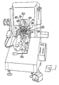
- the pulling over and toe lasting machine shown in Fig. 1 and now to be described comprises a shoe support 10, which is elongated in the lengthwise direction of a shoe to be supported thereby, and an adhesive applicator device 11 which surrounds the shoe support 10, whereby adhesive can be applied to toe and forepart portions of the insole of a shoe supported by the shoe support.
- a pincer assembly Arranged in an array about the applicator device 11 is a pincer assembly generally designated 114, comprising a toe pincer 116 and, at each side thereof, four side pincers 118.
- the machine comprises a wiper assembly generally designated 120 and a toe band 122 which engages the toe end of a shoe supported by the shoe support 10 while leaving unclamped the depending lasting marginal portions of the shoe upper in the toe and forepart region thereof.
- a toe pad 124 Above the shoe support 10 and to one side thereof is a toe pad 124 which is movable firstly into a position in opposed relationship with the shoe support and downwardly theretowards, the toe pad cooperating with the wiper assembly 120 to apply bedding pressure to the shoe in the course of the lasting operation.
- the machine also comprises a heel support arrangement generally designated 126 by which the heel end portion of a shoe is engaged, during the lasting cycle, in order to support the heel end of the shoe. It will thus be appreciated that the machine is generally similar, except as hereinafter described, to a conventional so-called "fixed head” pulling over and toe lasting machine.
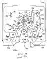
- the wiper assembly 120 (Fig. 2) comprises a base plate 122 which is fixed in the machine and mounted on which, but spaced therefrom, is a cam plate 170 provided with two sets of cam slots 124 (one set being shown in full line and the position of the other set being indicated in chain-dot line in Fig. 2).
- cam slots are accommodated pins 126 mounted on a wiper carrier 128, there being thus two such wiper carriers arranged side-by-side in the wiper assembly.
- each wiper carrier for effecting such linear forward movement, furthermore, there is pivotally connected to each wiper carrier a link 130, said links being in turn connected pivotally with a cross-member (not shown) which is driven by means of a piston-and-cylinder arrangement (also not shown), constituting drive means of the wiper assembly.
- the arrangement for effecting such forward and inward movement of the wiper carriers is also conventional.
- the wiper plate arrangement of the aforementioned wiper assembly comprises a first, toe, wiper plate 132 which is mounted on the wiper carrier 128 for pivotal adjusting movement about a pivot 134. More particularly, the wiper plate 132 is provided with an arcuate slot 136, whose centre of curvature is at the pivot 134, and there is provided on the wiper carrier a pin 138 which is accommodated in the slot 136 thus to guide the wiper plate during adjustment of its position in relation to the wiper carrier.
- the pin 138 also carries a clamp arrangement 140 whereby, after the position of the wiper plate has been adjusted, it can be clamped in said position.
- the wiper carrier is provided with an arcuate guide surface 142 which cooperates with a complementarily shaped rear surface of the wiper plate.
- the wiper plate 132 thus provides a portion of the leading edge 144 of the wiper assembly 120 and a portion of the wiping surface 146 thereof.
- the wiper plate 132 is formed with an integral "button" 148 and in overlapping relationship therewith is arranged a complementarily shaped button 150 formed on a second, forepart, wiper plate 152, the two buttons 148, 150, providing a pivotal connection, at the pivot 154 between the two wiper plates, 132, 152.
- the forepart wiper plate is held constrained, by a bifurcated extension 128 a of the wiper carrier, for pivotal movement about the pivot 154.
- the bifurcated extension 128 a supports an adjustment screw 156 a forward end of which engages with the rear surface of the wiper plate 152 thus to set the rearward position of the plate 152 about the pivot 154.
- a suitable clamp arrangement 158 may again be provided; alternatively, provided that the wiper plate 152 is held against the abutment 156, e.g. by springs, when the machine is idle, it will be appreciated that contact of the wiper plate with the shoe will urge the plate into engagement with the abutment in any event.
- the two toe wiper plates 132 are, as has already been mentioned, pivoted about the pivot 134.
- a separate button 160 is provided and each wiper plate 132 has an arcuately cut-away portion whereby it can "mate” with said button 160.
- the button 160 is carried on a slide 162 which is accommodated in a groove 164 formed in the base plate 122.
- the slide 162 has an upstanding lug 166 which can be engaged by a projection 168 formed on the wiper carrier 128 of the right-hand wiper plate arrangement. In this way, when forward linear movement is transmitted to the wiper carrier 128, the button 160 is moved through a commensurate distance therewith.
- the button arrangement may be provided in a manner similar to the button arrangement 148, 150 by which the two wiper plates 132, 152 are connected, or by the button being formed integral with one of said plates and mating with a cut-away portion formed in the other.
- button arrangement 148, 150 may be replaced by an independent button arrangement along the lines of the button arrangement 160; in this case, no sliding movement of said button arrangement would take place, but its position in relation to the pivot 134 would be adjustable commensurately with the adjustment of the position of the toe wiper plate 132.
- the button arrangements should provide a smooth or substantially smooth planar surface with the adjacent portions of the wiper plates 132, 152, as the case may be.
- the wiping surface 146 of the wiper plate is chamfered, there will of course be inevitably some stepping of the button surfaces according to the angular relationships between the various wiper plates, but such stepping should be maintained at a minimum.
- a continuous wiping surface it is intended that such surface may include some, relatively insignificant, stepping in the vicinity of the pivotal connections between the various plates.
- the configuration of the continuous surface 146, and of the wiper edge 144 is adjusted manually prior to a cycle of operation of the machine being initiated. Once this configuration has been determined, furthermore, the operation of the machine is generally as a conventional pulling over and toe lasting machine.
- a suitable drive may be provided by which the arcuate rearward surface of the toe wiper plate 132 can be engaged, e.g. a worm and rack arrangement, the drive also including a flexible drive shaft connected to a suitably disposed operator-actuatable knob; similarly, the abutment screw 156 could be connected by a flexible drive to a suitably disposed operator-actuatable knob.
- the worm and rack are brought into engagement only when the wiper plate is in its rest position, thereby reducing the need for moving the whole of the adjusting mechanism during the lasting operation.
- pattern data may be stored in a memory of the control means and control or drive signals may be supplied, in response to such pattern data, to stepping motors or other n.c. motors forming part of the drive arrangements.
- the clamping arrangements would also have to be automatically operated and released.
- the configuration of the continuous wiping surface 146 and its associated leading wiper edge 144 can be readily set individually to each shoe to be operated upon.
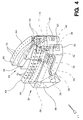
- a top plate 222 is provided in which is formed a continuous arcuate groove 224 having a centre 234.
- mounted for arcuate movement about the centre 234 are two wiper plate arrangements each comprising a wiper carrier 228, which is provided with an arcuate guide flange 226 formed complementarily with and accommodated in a portion of the groove 224.
- a first, toe, wiper plate 232 Secured to the wiper carrier 228 is a first, toe, wiper plate 232 having a rearward edge which engages along a surface of the flange 226 and providing a toe part of a continuous wiping surface 246 and of a continuous leading edge 244 of the wiper assembly.
- the wiper carrier 228 also is itself formed with an arcuate groove the centre of curvature of which lies at a pivot 254 about which a second, forepart, wiper plate 252 is mounted for pivotal movement.
- the wiper plate 252 is itself formed with an integral guide rib 276 which is arcuate and is formed complementarily to and accommodated in the groove 274. The wiper plate 252 is thus guided for arcuate movement about the pivot 254.
- a central button arrangement 260 is provided having a surface portion which forms with the adjacent surface portions of the toe wiper plates 232 a continuous wiping surface.
- the button 260 is supported by an integral carrier which is secured to the top plate 222. In this way, the central button is fixed in relation to the top plate.
- the wiper plates 232, 252 are pivotally connected to one another by a further button arrangement made up of a button portion 250 formed integral with the forepart wiper plate 252 and cooperating with a complementarily shaped cut-out 248 formed in the toe wiper plate 232.
- the central button may be provided by overlapping or complementarily shaped portions of the two toe wiper plates 232 inter-engaging, while similarly each button arrangement 248, 250 may be formed by the provision of an independent button arrangement mounted on the wiper carrier 228.
- Each wiper plate arrangement is also provided with a base plate 278, bolted to the top plate 222 and forming a "sandwich" therewith thus to contain the wiper plates 232, 252 therebetween.
- the two wiper plate arrangements and the top plate described so far are supported in a further “sandwich” comprising a base plate 270 bolted to the machine frame and a cover plate 280 secured to the base plate but spaced therefrom by spacer bars 282, the latter serving also to guide the top plate 222 for sliding movement within the space between the base and cover plates 270, 280.
- the second wiper assembly it is no longer a question of adjusting the relative positions of the wiper plates about the centres 234, 254 prior to the lasting operation being initiated, but rather a question of effecting movement of the various wiper plates in an optimum manner during the lasting operation. That is to say, in this case the configuration of the continuous wiping edge 244 and continuous wiping surface 246 is varied during the lasting operation, thus to accommodate appropriately to each shoe shape.
- any suitable drive means may be provided, but this second wiper assembly is especially suitable for use in a machine provided with electronic control means, the drive means for the various wiper plates thus being constituted by drive arrangements including stepping motors or other n.c. motors.
- a worm and rack arrangement as referred to in connection with the first wiper assembly 120 may be utilised in each case. It will of course be appreciated that in this event the worm and rack are maintained constantly in engagement.
- a similar drive arrangement is provided for moving the top plate 222 (which thus constitutes a carriage for the wiper plate arrangements supported thereby) linearly forwardly whereby to cause the button arrangement 260 to wipe the lasting marginal portion of the upper, in the backseam region, over and press it against the corresponding marginal portion of the insole, such drive arrangement operating in timed relation with the drive means for the wiper plates.
- the wiping edge be accommodated to each size and style of shoe specifically, thereby accommodating not only rounded, pointed and square shoe toes in general, but being configurable to each variation of any one of these styles, but also, by using independent motors for each wiper plate, different configurations, and indeed different variations of configuration during the lasting cycle, may take place for left and right shoes.
- the wiper plates are conventionally brought to an intermediate position in which they have just crossed the edge of the insole, thereby trapping the margin of the shoe upper against the insole. In this position an adhesive-applying operation may take place using the adhesive applicator device 11, which device is then moved out of its adhesive-applying condition to an out-of-the-way position, whereafter the wiper movement is continued.
- the shape of the wiper plates, and in particular the leading edge thereof, and the shape of the adhesive applicator device must be matched; otherwise there is a risk of collision therebetween when the wiper assemblies are moved to their intermediate position.
- the adhesive applicator device 11 is also susceptible of variation of its configuration to take account of the difference styles and sizes of shoe to be operated upon.
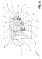
- the adhesive applicator device 11 comprises a block 12 which is provided with an internal recess by which the block can be accommodated at the upper end of a piston rod 14 of a piston-and-cylinder arrangement by which heightwise movement of the device 11 is effected.
- the block 12 is mounted for limited rocking movement on the piston rod and is held against rotation thereon by screw 16.
- the block 12 provides, at each side of the piston rod 14, a supporting surface 22, to be referred to hereinafter.
- the device 11 also comprises two melt chambers generally designated 24, each comprising a block 26 in which a heater element 28 is accommodated and which has an inlet 30 through which adhesive in solid rod form can be introduced into the melt chamber. By the heat supplied by heater 28, the adhesive rod is melted and flows along a passageway 32 to an outlet 34.
- each melt chamber has two lug portions 36, again formed with aligned bores 38.
- a pin 40 on which is carried a further support block 42 which is generally kidney-shaped in plan view.
- the two support blocks 42 are formed with inter-engaging lug portions, respectively at the end thereof remote from the pin 40, and the lug portions are formed with bores 44 which can thus be aligned not only with each other but also with the bores 20 formed in the block 12.
- a pin 46 Fig. 6
- the support surfaces 22 provided by the block 12 also serve to provide a support for the melt chambers 24.
- two rotary wheels 56 are provided centrally of the rod 54, said wheels being spaced from one another and being held against displacement in a direction lengthwise of the rod by a lug 58 formed on the underside of the forwardly projecting portion of the block 12.
- Similar adjusting means is provided for varying the distance between the ends of the melt chambers 24 remote from the pin 46 and to this end there is mounted on the underside of the block 26 of each melt chamber a further support block 58, and a further rod 60 having opposite-handed threaded end portions is carried by the two blocks, said rod being provided with a pair of centrally disposed rotary wheels 62 spaced apart and held captive, against transverse movement, by a depending lug formed on the block 12.
- a continuous adhesive-applying surface 64 is provided by means of a plurality (in casu 4) elements 66, 68, supported by the blocks 26 and support blocks 42 as will now be described.
- Each element 66 which constitutes a "leg" element of the generally U-shaped configuration of the continuous surface 64, is secured by screws (not shown) to the upper surface of its associated block 26, such that an inlet passage 70 thereof coincides with the outlet 34 of the block 26.
- the inlet 70 is connected through internal passages formed in the element 66 to outlets 72 which open into the continuous surface 64.
- the elements 68 are formed with inter-engaging lug portions (see especially Figs.
- each element 68 and its adjacent element 66 are also formed with inter-engaging lug portions having bores, one (74) of which is blind, aligned with the bores 38, for receiving the upper end portion of the respective pin 40.
- adhesive is supplied to each element 68 from the melt chamber 24 associated with its associated element 66.
- the passage 32 formed in the block 26 has a branch 76 which is connected to a passage formed in the pin 40, which is thus tubular.
- the upper end of the pin 40 opens into the blind bore 74 into which also opens an internal passageway 78 formed in the element 68 and itself opening through outlet 72 into the continuous surface 64.
- variable-configuration adhesive applicator device 11 in conjunction with either one of the wiper assemblies 120, 220 in accordance with the present invention, a fully adjustable system is provided which enables the need for so-called “bespoke” fittings, conventional in currently available pulling over and toe lasting machines, to be dispensed with.
- the configuration of the continuous wiping surface 246 and leading edge 244 of the wiper assembly can be “tailored” specifically to the requirements made by the shoe shape not only as a general compromise at the start of the lasting operation, but actually during the lasting cycle.
Landscapes
- Footwear And Its Accessory, Manufacturing Method And Apparatuses (AREA)
- Braking Arrangements (AREA)
- Feeding Of Articles By Means Other Than Belts Or Rollers (AREA)
- Orthopedics, Nursing, And Contraception (AREA)
Applications Claiming Priority (2)
| Application Number | Priority Date | Filing Date | Title |
|---|---|---|---|
| GB888809499A GB8809499D0 (en) | 1988-04-22 | 1988-04-22 | Wiper assembly for shoe lasting machine |
| GB8809499 | 1988-04-22 |
Publications (3)
| Publication Number | Publication Date |
|---|---|
| EP0338722A2 true EP0338722A2 (de) | 1989-10-25 |
| EP0338722A3 EP0338722A3 (de) | 1991-04-03 |
| EP0338722B1 EP0338722B1 (de) | 1995-08-02 |
Family
ID=10635624
Family Applications (1)
| Application Number | Title | Priority Date | Filing Date |
|---|---|---|---|
| EP89303648A Expired - Lifetime EP0338722B1 (de) | 1988-04-22 | 1989-04-12 | Schere für Schuhzwickmaschine |
Country Status (5)
| Country | Link |
|---|---|
| US (1) | US5025521A (de) |
| EP (1) | EP0338722B1 (de) |
| KR (1) | KR970002514B1 (de) |
| DE (1) | DE68923644T2 (de) |
| GB (1) | GB8809499D0 (de) |
Cited By (5)
| Publication number | Priority date | Publication date | Assignee | Title |
|---|---|---|---|---|
| EP0585982A1 (de) * | 1992-09-04 | 1994-03-09 | OFFICINE MECCANICHE MOLINA & BIANCHI S.p.A. | Vorrichtung zum Falten einer Kante des Oberleders auf einer Leiste von einer Schuhherstellungsmaschine |
| WO1995028104A1 (en) * | 1994-04-19 | 1995-10-26 | British United Shoe Machinery Limited | Pulling over and toe lasting machine |
| EP1036516A1 (de) * | 1999-03-18 | 2000-09-20 | OFFICINE MECCANICHE MOLINA & BIANCHI S.p.A. | Maschine zur Herstellung von Schuhen |
| EP1491108A1 (de) * | 2003-06-24 | 2004-12-29 | OFFICINE MECCANICHE MOLINA & BIANCHI S.p.A. | Vorrichtung zum Falten der Kante eines Schuhoberteils |
| RU2365320C2 (ru) * | 2007-06-13 | 2009-08-27 | Владислав Александрович Прокофьев | Способ и устройство для обтяжки и затяжки носочно-геленочной части обуви |
Families Citing this family (2)
| Publication number | Priority date | Publication date | Assignee | Title |
|---|---|---|---|---|
| TW201404326A (zh) * | 2013-09-30 | 2014-02-01 | kun-zhong Liu | 免縫鞋面的製造方法 |
| KR101975480B1 (ko) * | 2018-05-08 | 2019-08-28 | 이승희 | 클린룸안전화의 보호패드 가압접합장치 |
Family Cites Families (9)
| Publication number | Priority date | Publication date | Assignee | Title |
|---|---|---|---|---|
| US3196470A (en) * | 1963-10-04 | 1965-07-27 | United Shoe Machinery Corp | Wiper means for lasting machines |
| DE1485929A1 (de) * | 1964-05-14 | 1969-04-10 | Eugen G Henkel Fa | Zwickmaschine |
| US3258799A (en) * | 1965-05-10 | 1966-07-05 | Eugen G Henkel | Lasting machine |
| DE1685440A1 (de) * | 1966-03-09 | 1971-05-13 | Moenus Ag Maschinenfabrik Fuer | Zwickscheren-Hubeinrichtung fuer UEberhol-,Spitzen- und Ballenzwickmaschine |
| DE2021376B2 (de) * | 1970-04-30 | 1973-05-24 | Deutsche Vereinigte Schuhmaschinen Gmbh, 6000 Frankfurt | Vorrichtung zur betaetigung der zwickschere einer spitzenzwickmaschine |
| DE3131696C2 (de) * | 1981-08-11 | 1985-03-07 | Maschinenfabrik Moenus-Turner Gmbh, 6000 Frankfurt | Schuhzwickmaschine |
| DE3245120A1 (de) * | 1982-12-07 | 1984-06-07 | Internationale Schuh-Maschinen Co Gmbh, 6780 Pirmasens | Vorrichtung zum spitzen- und ballenzwicken einer schuheinheit |
| US4517697A (en) * | 1983-10-14 | 1985-05-21 | International Shoe Machine Corporation | Adhesive applicator |
| GB8606215D0 (en) * | 1986-03-13 | 1986-04-16 | Busm Co Ltd | Machine for shoe uppers |
-
1988
- 1988-04-22 GB GB888809499A patent/GB8809499D0/en active Pending
-
1989
- 1989-04-12 DE DE68923644T patent/DE68923644T2/de not_active Expired - Fee Related
- 1989-04-12 EP EP89303648A patent/EP0338722B1/de not_active Expired - Lifetime
- 1989-04-18 US US07/339,974 patent/US5025521A/en not_active Expired - Fee Related
- 1989-04-21 KR KR1019890005280A patent/KR970002514B1/ko not_active Expired - Lifetime
Cited By (5)
| Publication number | Priority date | Publication date | Assignee | Title |
|---|---|---|---|---|
| EP0585982A1 (de) * | 1992-09-04 | 1994-03-09 | OFFICINE MECCANICHE MOLINA & BIANCHI S.p.A. | Vorrichtung zum Falten einer Kante des Oberleders auf einer Leiste von einer Schuhherstellungsmaschine |
| WO1995028104A1 (en) * | 1994-04-19 | 1995-10-26 | British United Shoe Machinery Limited | Pulling over and toe lasting machine |
| EP1036516A1 (de) * | 1999-03-18 | 2000-09-20 | OFFICINE MECCANICHE MOLINA & BIANCHI S.p.A. | Maschine zur Herstellung von Schuhen |
| EP1491108A1 (de) * | 2003-06-24 | 2004-12-29 | OFFICINE MECCANICHE MOLINA & BIANCHI S.p.A. | Vorrichtung zum Falten der Kante eines Schuhoberteils |
| RU2365320C2 (ru) * | 2007-06-13 | 2009-08-27 | Владислав Александрович Прокофьев | Способ и устройство для обтяжки и затяжки носочно-геленочной части обуви |
Also Published As
| Publication number | Publication date |
|---|---|
| DE68923644D1 (de) | 1995-09-07 |
| KR970002514B1 (ko) | 1997-03-05 |
| GB8809499D0 (en) | 1988-05-25 |
| EP0338722B1 (de) | 1995-08-02 |
| KR900015655A (ko) | 1990-11-10 |
| EP0338722A3 (de) | 1991-04-03 |
| US5025521A (en) | 1991-06-25 |
| DE68923644T2 (de) | 1996-01-11 |
Similar Documents
| Publication | Publication Date | Title |
|---|---|---|
| US5025521A (en) | Shoe lasting machine | |
| US5722103A (en) | Toe and side and heel lasting machine and method of lasting | |
| EP1036516B1 (de) | Maschine zur Herstellung von Schuhe | |
| US4407033A (en) | Combination toe and side lasting machine | |
| CA1186460A (en) | Toe lasting machine with adjustable heel clamp pad | |
| EP0209282B1 (de) | Überhol- und Aufzwickmaschine für das Spitzenteil | |
| EP0338725B1 (de) | Klebstoffauftragvorrichtung | |
| US4499622A (en) | Gripper assembly | |
| US4517697A (en) | Adhesive applicator | |
| GB2052950A (en) | Machine for lasting heel seat portions of shoes | |
| US3090980A (en) | Apparatus for shaping and lasting the heel end of shoes | |
| GB2118867A (en) | Machine for lasting side portions of shoes | |
| EP0756462A1 (de) | Überhol- und aufzwickmaschine für das spitzenteil | |
| US4491997A (en) | Machine for lasting heel seat portions of shoes | |
| US4744120A (en) | Shoe support for shoe upper conforming machine | |
| US4404700A (en) | Machine for lasting side portions of shoes | |
| CA1173605A (en) | Combination toe and side lasting machine | |
| EP0091299B1 (de) | Maschine zum Zwicken des Fersenbereiches von Schuhen | |
| US4322863A (en) | Machine for lasting heel seat portions of shoes | |
| CA1135461A (en) | Machine for lasting heel seat portions of shoes | |
| EP0247831B1 (de) | Seiten- und Fersenzwickmaschine | |
| US5678269A (en) | Toe and side and heel lasting machine and method of lasting | |
| EP0091300A1 (de) | Seitenzwickmaschine | |
| US4377876A (en) | Shoe lasting machine | |
| EP0585982A1 (de) | Vorrichtung zum Falten einer Kante des Oberleders auf einer Leiste von einer Schuhherstellungsmaschine |
Legal Events
| Date | Code | Title | Description |
|---|---|---|---|
| PUAI | Public reference made under article 153(3) epc to a published international application that has entered the european phase |
Free format text: ORIGINAL CODE: 0009012 |
|
| AK | Designated contracting states |
Kind code of ref document: A2 Designated state(s): DE GB IT |
|
| PUAL | Search report despatched |
Free format text: ORIGINAL CODE: 0009013 |
|
| AK | Designated contracting states |
Kind code of ref document: A3 Designated state(s): DE GB IT |
|
| 17P | Request for examination filed |
Effective date: 19910913 |
|
| 17Q | First examination report despatched |
Effective date: 19930716 |
|
| RAP1 | Party data changed (applicant data changed or rights of an application transferred) |
Owner name: DVSG ENGINEERING UND PATENTVERWALTUNGS GMBH Owner name: DEUTSCHE VEREINIGTE SCHUHMASCHINEN GMBH Owner name: BRITISH UNITED SHOE MACHINERY LIMITED |
|
| RAP1 | Party data changed (applicant data changed or rights of an application transferred) |
Owner name: DVSG ENGINEERING UND PATENTVERWALTUNGS GMBH Owner name: DEUTSCHE VEREINIGTE SCHUHMASCHINEN GMBH Owner name: BRITISH UNITED SHOE MACHINERY LIMITED |
|
| GRAA | (expected) grant |
Free format text: ORIGINAL CODE: 0009210 |
|
| AK | Designated contracting states |
Kind code of ref document: B1 Designated state(s): DE GB IT |
|
| REF | Corresponds to: |
Ref document number: 68923644 Country of ref document: DE Date of ref document: 19950907 |
|
| ITF | It: translation for a ep patent filed | ||
| PGFP | Annual fee paid to national office [announced via postgrant information from national office to epo] |
Ref country code: GB Payment date: 19960327 Year of fee payment: 8 |
|
| PLBE | No opposition filed within time limit |
Free format text: ORIGINAL CODE: 0009261 |
|
| STAA | Information on the status of an ep patent application or granted ep patent |
Free format text: STATUS: NO OPPOSITION FILED WITHIN TIME LIMIT |
|
| 26N | No opposition filed | ||
| PGFP | Annual fee paid to national office [announced via postgrant information from national office to epo] |
Ref country code: DE Payment date: 19970324 Year of fee payment: 9 |
|
| PG25 | Lapsed in a contracting state [announced via postgrant information from national office to epo] |
Ref country code: GB Effective date: 19970412 |
|
| GBPC | Gb: european patent ceased through non-payment of renewal fee |
Effective date: 19970412 |
|
| PG25 | Lapsed in a contracting state [announced via postgrant information from national office to epo] |
Ref country code: DE Free format text: LAPSE BECAUSE OF NON-PAYMENT OF DUE FEES Effective date: 19990202 |
|
| PG25 | Lapsed in a contracting state [announced via postgrant information from national office to epo] |
Ref country code: IT Free format text: LAPSE BECAUSE OF NON-PAYMENT OF DUE FEES;WARNING: LAPSES OF ITALIAN PATENTS WITH EFFECTIVE DATE BEFORE 2007 MAY HAVE OCCURRED AT ANY TIME BEFORE 2007. THE CORRECT EFFECTIVE DATE MAY BE DIFFERENT FROM THE ONE RECORDED. Effective date: 20050412 |