EP0338541A2 - Machine-outil pour travailler des pièces dans des configurations à section transversale non circulaire - Google Patents
Machine-outil pour travailler des pièces dans des configurations à section transversale non circulaire Download PDFInfo
- Publication number
- EP0338541A2 EP0338541A2 EP89107061A EP89107061A EP0338541A2 EP 0338541 A2 EP0338541 A2 EP 0338541A2 EP 89107061 A EP89107061 A EP 89107061A EP 89107061 A EP89107061 A EP 89107061A EP 0338541 A2 EP0338541 A2 EP 0338541A2
- Authority
- EP
- European Patent Office
- Prior art keywords
- axis
- work piece
- circular cross
- tool
- servo motor
- Prior art date
- Legal status (The legal status is an assumption and is not a legal conclusion. Google has not performed a legal analysis and makes no representation as to the accuracy of the status listed.)
- Granted
Links
Images


Classifications
-
- G—PHYSICS
- G05—CONTROLLING; REGULATING
- G05B—CONTROL OR REGULATING SYSTEMS IN GENERAL; FUNCTIONAL ELEMENTS OF SUCH SYSTEMS; MONITORING OR TESTING ARRANGEMENTS FOR SUCH SYSTEMS OR ELEMENTS
- G05B19/00—Program-control systems
- G05B19/02—Program-control systems electric
- G05B19/18—Numerical control [NC], i.e. automatically operating machines, in particular machine tools, e.g. in a manufacturing environment, so as to execute positioning, movement or co-ordinated operations by means of program data in numerical form
- G05B19/182—Numerical control [NC], i.e. automatically operating machines, in particular machine tools, e.g. in a manufacturing environment, so as to execute positioning, movement or co-ordinated operations by means of program data in numerical form characterised by the machine tool function, e.g. thread cutting, cam making, tool direction control
- G05B19/184—Generation of cam-like surfaces
-
- G—PHYSICS
- G05—CONTROLLING; REGULATING
- G05B—CONTROL OR REGULATING SYSTEMS IN GENERAL; FUNCTIONAL ELEMENTS OF SUCH SYSTEMS; MONITORING OR TESTING ARRANGEMENTS FOR SUCH SYSTEMS OR ELEMENTS
- G05B2219/00—Program-control systems
- G05B2219/30—Nc systems
- G05B2219/36—Nc in input of data, input key till input tape
- G05B2219/36197—Non circular workpiece, radius and angle input
-
- G—PHYSICS
- G05—CONTROLLING; REGULATING
- G05B—CONTROL OR REGULATING SYSTEMS IN GENERAL; FUNCTIONAL ELEMENTS OF SUCH SYSTEMS; MONITORING OR TESTING ARRANGEMENTS FOR SUCH SYSTEMS OR ELEMENTS
- G05B2219/00—Program-control systems
- G05B2219/30—Nc systems
- G05B2219/41—Servomotor, servo controller till figures
- G05B2219/41457—Superposition of movement
-
- G—PHYSICS
- G05—CONTROLLING; REGULATING
- G05B—CONTROL OR REGULATING SYSTEMS IN GENERAL; FUNCTIONAL ELEMENTS OF SUCH SYSTEMS; MONITORING OR TESTING ARRANGEMENTS FOR SUCH SYSTEMS OR ELEMENTS
- G05B2219/00—Program-control systems
- G05B2219/30—Nc systems
- G05B2219/49—Nc machine tool, till multiple
- G05B2219/49118—Machine end face, control C-axis and X-axis
-
- G—PHYSICS
- G05—CONTROLLING; REGULATING
- G05B—CONTROL OR REGULATING SYSTEMS IN GENERAL; FUNCTIONAL ELEMENTS OF SUCH SYSTEMS; MONITORING OR TESTING ARRANGEMENTS FOR SUCH SYSTEMS OR ELEMENTS
- G05B2219/00—Program-control systems
- G05B2219/30—Nc systems
- G05B2219/50—Machine tool, machine tool null till machine tool work handling
- G05B2219/50053—Machine non circular, non-round cross section, hexagonal, rectangular
-
- Y—GENERAL TAGGING OF NEW TECHNOLOGICAL DEVELOPMENTS; GENERAL TAGGING OF CROSS-SECTIONAL TECHNOLOGIES SPANNING OVER SEVERAL SECTIONS OF THE IPC; TECHNICAL SUBJECTS COVERED BY FORMER USPC CROSS-REFERENCE ART COLLECTIONS [XRACs] AND DIGESTS
- Y10—TECHNICAL SUBJECTS COVERED BY FORMER USPC
- Y10T—TECHNICAL SUBJECTS COVERED BY FORMER US CLASSIFICATION
- Y10T82/00—Turning
- Y10T82/25—Lathe
- Y10T82/2502—Lathe with program control
-
- Y—GENERAL TAGGING OF NEW TECHNOLOGICAL DEVELOPMENTS; GENERAL TAGGING OF CROSS-SECTIONAL TECHNOLOGIES SPANNING OVER SEVERAL SECTIONS OF THE IPC; TECHNICAL SUBJECTS COVERED BY FORMER USPC CROSS-REFERENCE ART COLLECTIONS [XRACs] AND DIGESTS
- Y10—TECHNICAL SUBJECTS COVERED BY FORMER USPC
- Y10T—TECHNICAL SUBJECTS COVERED BY FORMER US CLASSIFICATION
- Y10T82/00—Turning
- Y10T82/25—Lathe
- Y10T82/2531—Carriage feed
- Y10T82/2533—Control
-
- Y—GENERAL TAGGING OF NEW TECHNOLOGICAL DEVELOPMENTS; GENERAL TAGGING OF CROSS-SECTIONAL TECHNOLOGIES SPANNING OVER SEVERAL SECTIONS OF THE IPC; TECHNICAL SUBJECTS COVERED BY FORMER USPC CROSS-REFERENCE ART COLLECTIONS [XRACs] AND DIGESTS
- Y10—TECHNICAL SUBJECTS COVERED BY FORMER USPC
- Y10T—TECHNICAL SUBJECTS COVERED BY FORMER US CLASSIFICATION
- Y10T82/00—Turning
- Y10T82/25—Lathe
- Y10T82/2531—Carriage feed
- Y10T82/2533—Control
- Y10T82/2535—Electrical type
Definitions
- This invention relates to a machine tool for precisely processing a work piece into a non-circular cross-sectional configuration by inputting simplified data of such configuration.
- a conventional copying method using a pattern has a disadvantage of having to manufacture the pattern. Accordingly, such a method has recently been investigated that program data of a non-circular cross-sectional contour are worked out on a computer, by inputting the data of the contour, thereby processing the work piece through numerical control.
- the working fluid of an oil hydraulic cylinder is controlled to reciprocate a tool holder, under the control of a hydraulic servo mechanism.
- the control system is divided into a main and a sub parts: the main part controls the average diameter of the work piece requiring large movement by means of the conventional feed screw method, and the sub part controls the difference between the minimum and maximum diameters of each cross section of the work piece by means of the oil hydraulic cylinder.
- Such mechanism employing an oil hydraulic servo mechanism has a possibility that, in accordance with an increase in the frequency of the reciprocative movement of the cylinder in the X direction by speeding up the rotation of the work piece, a delay in the phase will occur and the amplitude will decrease. Further, since the oil hydraulic servo mechanism is operated at high speed, the temperature of the working fluid rises and the characteristics change, which results in a deterioration in processing precision because of heat displacement. Further, as the working fluid is compressive, it is influenced by a difference in cutting amount and resistance during cutting caused by the rotational speed of the work piece, which is a primary factor in causing a deterioration in processing precision.
- the conventional machine tool for processing a work piece into a non-circular cross-sectional configuration has the disadvantage that the data to be input amounting to several tens of thousands of numbers, is difficult to use easily, as in the above publicly-known instance.
- the present invention develops a structure of a machine tool for processing a work piece into a non-circular cross-sectional configuration and a control mechanism for use in this, as shown hereinafter, in order to maintain the precision of processing to extend over the whole stroke of movement of the tool holder, as well as to facilitate input by an operator.
- a characteristic of the machine tool for processing a work piece into a non-circular cross-sectional configuration is that, with respect to the work piece (1) being rotated continuously, in the case where a direction parallel to the rotation axis O is referred to as a Z axis, a direction perpendicular to the rotation axis an X axis and a rotating direction a C axis, the machine tool comprises a first X axis slider (2) provided relatively movable in the Z and X axis directions, a second X axis slider (3) supported on the first X axis slider (2) which is movable at high speed in the X direction, a second X axis servo motor (5) for moving a tool (4) secured to the second X axis slider (3) in the X axis direction at each position of the Z and rotational directions by a previously programmed command value, a spindle stock (7) including a C axis servo motor (6) for controlling the work piece (1) in the rotational direction
- the second X axis slider (3) is made of fine ceramic which is light, heat-resistant, non-expansible under heat and is highly wear-resistant, also a high precision ball screw and a servo motor are directly connected to each other. Consequently, according to the invention, the work piece can be processed at higher speed and more precisely.
- a control mechanism of the machine tool for processing a work piece in the invention is characterized in that the amount of movement of the second X axis servo motor (5), that is, the command of movement of the tool (4) in the X direction is calculated by finding coordinates at each position on the work piece from a function f( ⁇ , Z) of a rotation angle ⁇ from the reference plane of the work piece (1) and a distance Z from the reference point in the Z direction parallel to the rotation axis O, thereby forming a non-circular cross-sectional contour, and in that program data of the non-circular cross-sectional contour are calculated through the automatic operation device by inputting elements of the work piece in a simplified way, and transmitting them to the numerical control device so as to control the X axis servo motor provided with the tool.
- the elements of the work piece described above as easily inputtable are several, such as the distance (given as a dimension value in the drawing) from the reference point existing in the Z axis direction parallel to the rotation axis O to a processed configuration showing a reference cross section when the work piece is cut crosswise at an arbitrary position, a configuration of each cross section and so on.
- the elements are the minimum local dimension values and enough information to express the non-circular cross-sectional contour.
- the overall area is calculated by the automatic operation device (12) utilizing interpolation, and the data (P01, P02, P03, --- P A1 , P A2 --- P c1 , P c2 --- P ck-1 , P ck ), which amount to several tens of thousands of coordinates at the respective points on the work piece, are worked out so that they may be spiral and extend smoothly, considering the movement command of the tool (4) in the X direction as a function f( ⁇ , Z) of the rotation angle ⁇ from the reference plane of the work piece (1) and the distance Z from the reference point in the Z direction parallel to the rotation axis O according to the processing conditions (speed of rotation, cut-feed and so on).
- a large amount of data of the non-circular cross-sectional contour obtained in the above-mentioned manner are stored in a storage on a host computer and the data are stored in an inertial storage on the machine tool, as well.
- the data are transmitted to the numerical control device at need, controlling the X axis servo motor provided with the tool.
- a large amount of data of the non-circular cross-sectional contour are automatically operated solely on the basis of the input of the several elements of the work piece.
- the X axis servo motor disposed relatively movably in the Z and X directions as well as provided with the tool is controlled on the basis of the above data.
- the numerical control device (11) issues commands at high speed so as to form a non-circular cross-sectional configuration in the Z, C and second X directions.
- the first X axis slider (2) rapidly moves relatively in the Z and X directions with respect to the work piece (1) rotated continuously by means of the C axis servo motor (6) for controlling in the rotational direction.
- the second X axis slider (3) supported on the first X axis slider (2) moves in the X direction at high speed according to the command value by means of the second X axis servo motor (5).
- the first X axis slider operates to position roughly in the X direction according to the size of the work piece and it ordinarily stops during processing of the work piece.
- the second X axis slider (3) is made of fine ceramic, and when the second X axis servo motor (5) moves the second X axis slider (3) in the X axis direction at high speed in accordance with the command value, the second X axis slider can be moved securely because a highly precise ball screw is directly connected to the servo motor. Further, since the coefficient of heat expansion of fine ceramic is one fifth that of steel, highly precise processing can be carried out stably and for a long period of time.
- Fig. 1 is a plane view of a machine tool for processing a work piece into a non-circular cross-sectional configuration according to the present invention
- Fig. 2 is a side view of the same, viewed from the right side thereof
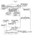
- Fig. 3 is a block diagram of the same.
- the machine tool of the invention comprises an automatic operation device (12) in which it is possible to input data in a more simplified way and thus a large amount of data concomitant with a non-circular cross-sectional contour are automatically put into operation; a numerical control device (11) which issues high-speed commands for forming the non-circular cross section in the three directions of an X axis, a C axis and a second X axis on the basis of the data; and a machine tool main body (10).
- the automatic operation device (12) mainly utilizes a personal computer, but it is not denied that high-speed data processing could be carried out by means of a large-sized computer.
- the simplified data are input to the automatic operation device (12) from a keyboard or online-input.
- a large amount of data of the non-circular cross-sectional contour obtained here are transmitted to the next numerical control device (11) and if necessary the data are stored and maintained in a diskette or a cassette by an external storage.
- the numerical control device (11) includes a program data storage (13) which stores controlling program data worked out by the automatic operation device (12), and a command signal producer (14) for producing command signals on the basis of the program data.
- a spindle stock (7) is provided on a bed (20) of the machine tool main body (10), and a chuck (8) for supporting a work piece (1) is disposed on a spindle (15) rotatably supported on the spindle stock (7). Movement in the rotational direction of the spindle (15) is controlled by a C axis servo motor (6) connected to the spindle through a coupling.
- a Z axis ball screw (16) which is rotated by a Z axis servo motor (17) connected to the end thereof.
- a Z axis slider (18) movable in the Z axis direction is fitted on the Z axis ball screw (16), and it is so arranged as to slidably engage with the bed (20) in the Z axis direction.
- a first X axis servo motor (21) is provided on the Z axis slider (18) in the X direction.
- the first X axis servo motor (21) rotates a first X axis ball screw (19) connected to the end thereof.
- a block-like first X axis slider (2) is engaged with the first X axis ball screw (19) so as to move relatively in the X direction.
- the first X axis slider (2) is a main slider, on which a second X axis servo motor (5) is provided in the X axis direction.
- the second X axis servo motor (5) rotates a second X axis ball screw (22) connected to the end thereof.
- a block-like second X axis slider (3) which is a sub slider is engaged with the second X axis ball screw (22).
- the second X axis slider (3) retains a tool (4).
- the second X axis slider (3) is made of light but strong fine ceramic, and a highly precise ball screw is utilized for the second X axis ball screw (22).
- a method for automatically calculating program data of the non-circular cross-sectional contour and a control method of the machine tool for processing a work piece into a non-circular cross-sectional configuration will now be described in more detail with reference to Figs. 4 to 8.
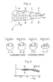
- Fig. 4 is an explanatory view of a work piece with a non-circular cross section to be processed by the invention
- Figs. 5(a) to 5(d) are cross-sectional views of the work piece with a non-circular cross section shown in Fig. 4, respectively at a series of points Z at arbitrary distances from the reference point in the Z direction
- Fig. 6 is an explanatory view showing the control amount of movement of the tool for processing the work piece
- Fig. 7 is an explanatory view of the control amount of movement of each axis during one rotation of the work piece
- Fig. 8 is a view showing a relation between the control amounts of movements of the first and second X axis sliders and the work piece.
- the cross section of the non-circular cross-sectional work piece shown in the drawing is circular between the reference end portion of the work piece and the line A-A′, as shown in Fig. 5(a). Therefore, as elements of the work piece, the following are input as data: the minimum radius ra at the reference point O and the fact that the cross section there is circular; the distance Z from the reference point O to the line A-A′ and the fact that the cross section there too is circular; again a minimum radius ra . It is not necessary to input the maximum radius rb because the cross section is circular.
- the cross section of the non-circular cross-sectional work piece at the line B-B′ is hexagonal.
- the following information is input: the distance Z from the reference point 0 to the line B-B′; the fact that the cross section is hexagonal; the minimum radius ra ; and the maximum radius rb .
- the cross sections at the line C-C′ and the line D-D′ are non-circular and elliptic; the distances from the reference point O to the respective lines, the minimum radii ra and the maximum radii rb in the respective cases are all input.
- the function ( ⁇ , Z) of the distances Z from the reference point in the Z direction is shown in Fig. 6. It is seen that there is an amplitude between the locus of the tool at the point of the maximum radius and the locus of the tool at the point of the minimum radius.
- the average radius between the maximum and minimum radii is not important in the invention.
- Fig.8 shows the above by the relation between the control amounts of movements of the first and second X axis sliders and the work piece.
- the first X axis slider (2) shown in the drawing displaces rapidly for the distance of f1 obtained by reducing the value of the maximum radius rb from the distance between the reference point O and the distal end of the tool (4) supported by the second X axis slider (3), under the program command, thereby being ready for the processing of the amplitude (f2) between the locus of the tool at the point of the maximum radius and the locus of the tool at the point of the minimum radius by the second X axis slider (3).
- a large amount of data of the non-circular cross-sectional contour are automatically operated on the basis of only the input of several elements of the work pieces.
- the X axis servo motor which is disposed relatively movably in the X and Z axis directions and provided with the tool is controlled on the basis of the above data.
- the numerical control device issues commands at high speed in order to form the work pieces into the non-circular cross-sectional configuration in the three directions of the Z axis, C axis and second X axis, the first X axis slider of the main slider relatively rapidly moving the tool in the Z axis and X axis directions with respect to the work piece rotated continuously, and the second X axis slider of the sub slider moving in the X direction to process the work piece at high speed in accordance with the command value, whereby it becomes possible to automatically process the work piece at high speed.
Landscapes
- Engineering & Computer Science (AREA)
- Human Computer Interaction (AREA)
- Manufacturing & Machinery (AREA)
- Physics & Mathematics (AREA)
- General Physics & Mathematics (AREA)
- Automation & Control Theory (AREA)
- Numerical Control (AREA)
- Turning (AREA)
Applications Claiming Priority (2)
| Application Number | Priority Date | Filing Date | Title |
|---|---|---|---|
| JP99095/88 | 1988-04-20 | ||
| JP63099095A JP2672970B2 (ja) | 1988-04-20 | 1988-04-20 | 非円形断面体ワーク加工用工作機械及びその制御方法 |
Publications (3)
| Publication Number | Publication Date |
|---|---|
| EP0338541A2 true EP0338541A2 (fr) | 1989-10-25 |
| EP0338541A3 EP0338541A3 (fr) | 1992-03-04 |
| EP0338541B1 EP0338541B1 (fr) | 1995-07-05 |
Family
ID=14238316
Family Applications (1)
| Application Number | Title | Priority Date | Filing Date |
|---|---|---|---|
| EP89107061A Expired - Lifetime EP0338541B1 (fr) | 1988-04-20 | 1989-04-19 | Machine-outil pour travailler des pièces dans des configurations à section transversale non circulaire |
Country Status (4)
| Country | Link |
|---|---|
| US (1) | US5085109A (fr) |
| EP (1) | EP0338541B1 (fr) |
| JP (1) | JP2672970B2 (fr) |
| DE (1) | DE68923316T2 (fr) |
Cited By (4)
| Publication number | Priority date | Publication date | Assignee | Title |
|---|---|---|---|---|
| WO1991011760A1 (fr) * | 1990-01-27 | 1991-08-08 | Matrix Churchill Limited | Appareil de machine-outil |
| EP0479026A1 (fr) * | 1990-10-02 | 1992-04-08 | Ex-Cell-O GmbH | Machine pour ovaliser des pièces à usiner |
| EP0476678A3 (en) * | 1990-09-20 | 1994-09-21 | Toyoda Machine Works Ltd | Method and apparatus for machining a non-circular workpiece |
| WO2011026481A1 (fr) * | 2009-09-04 | 2011-03-10 | Mahle International Gmbh | Procédé de fabrication d'un piston pour un moteur à combustion interne |
Families Citing this family (17)
| Publication number | Priority date | Publication date | Assignee | Title |
|---|---|---|---|---|
| US5315526A (en) * | 1989-12-07 | 1994-05-24 | Okuma Corporation | Numerically controlled lathe |
| JPH0396172U (fr) * | 1990-01-18 | 1991-10-01 | ||
| JPH05200601A (ja) * | 1992-01-24 | 1993-08-10 | Takizawa Tekkosho:Kk | 工作機械 |
| US5676030A (en) * | 1995-08-14 | 1997-10-14 | Crudgington Machine Tools, Inc. | Multi-spindle CNC lathe |
| WO2000020148A1 (fr) * | 1996-10-02 | 2000-04-13 | Schauer Mathias P | Dispositif de fixation pour tour |
| US5816123A (en) * | 1996-10-02 | 1998-10-06 | Schauer; Mathias P. | Attachment for a lathe |
| US6202521B1 (en) | 1998-12-14 | 2001-03-20 | Lord Corporation | Method, apparatus and controller for machining non-circular work pieces |
| EP1698953A1 (fr) * | 2005-03-02 | 2006-09-06 | Yamazaki Mazak Corporation | Dispositif de tournage de formes non circulaires avec plusieurs outils |
| JP5314358B2 (ja) * | 2008-08-25 | 2013-10-16 | シチズンマシナリーミヤノ株式会社 | 工作機械 |
| US8827611B2 (en) | 2011-06-10 | 2014-09-09 | Apple Inc. | Free form cutting machine |
| JP6533071B2 (ja) * | 2014-05-15 | 2019-06-19 | 東芝機械株式会社 | 非円形孔の加工方法、非円形孔の加工装置およびレンズ |
| JP5908182B1 (ja) * | 2014-10-17 | 2016-04-26 | 三菱電機株式会社 | 振動切削加工診断装置 |
| RU2018124639A (ru) * | 2015-12-21 | 2020-01-09 | Ипротек Машинен- Унд Эдельштальпродукте Гмбх | Электрическая рабочая машина |
| CN107020392B (zh) * | 2017-05-02 | 2020-12-08 | 陕西柴油机重工有限公司 | 一种中凸变椭圆曲线加工方法 |
| CN108296876A (zh) * | 2017-12-28 | 2018-07-20 | 昆山博古特机电设备有限公司 | Cnc高速钻攻系统 |
| CN113110287A (zh) * | 2021-04-22 | 2021-07-13 | 广东机电职业技术学院 | 一种背板并片非圆车削加工控制系统及其控制方法 |
| JP2024098290A (ja) * | 2023-01-10 | 2024-07-23 | シチズン時計株式会社 | 工作機械及び制御装置 |
Family Cites Families (13)
| Publication number | Priority date | Publication date | Assignee | Title |
|---|---|---|---|---|
| GB1062818A (en) * | 1963-08-09 | 1967-03-22 | Toyo Kogyo Kabushiki Kaisha | Rotating type cam grinding machine |
| US3616578A (en) * | 1969-01-10 | 1971-11-02 | Ingersoll Milling Machine Co | Method for turning workpieces |
| FR2267584B1 (fr) * | 1974-04-11 | 1978-01-13 | Renault | |
| DE2724808C3 (de) * | 1977-06-02 | 1980-01-17 | Purolator Filter Gmbh, 7110 Oehringen | Antriebsvorrichtung für die Quervorschubbewegung des Werkzeugs an Einrichtungen zum Materia] abtragenden Bearbeiten von Drehteilen |
| DE2732354C3 (de) * | 1977-07-18 | 1981-09-10 | Goetze Ag, 5093 Burscheid | Drehmaschine für die Unrundbearbeitung, insbesondere von Kolbenringen |
| JPS601122B2 (ja) * | 1979-03-23 | 1985-01-12 | 株式会社大隈「鉄」工所 | 同時4軸数値制御旋盤のロ−デイング方法 |
| US4343206A (en) * | 1980-06-12 | 1982-08-10 | The United States Of America As Represented By The United States Department Of Energy | Slide system for machine tools |
| JPS5919605A (ja) * | 1982-07-20 | 1984-02-01 | Toyota Motor Corp | 非真円形状切削加工装置 |
| JPH0657302B2 (ja) * | 1983-07-13 | 1994-08-03 | 株式会社東芝 | 中空糸膜フイルタの逆洗方法 |
| JPS618203A (ja) * | 1984-06-19 | 1986-01-14 | Res Dev Corp Of Japan | 非円形輪郭を形成する工作機械 |
| JPS618202A (ja) * | 1984-06-19 | 1986-01-14 | Res Dev Corp Of Japan | 非円形断面を有する物品の工作機械 |
| US4653360A (en) * | 1985-05-07 | 1987-03-31 | The Cross Company | CNC turning machine |
| DE3638698C2 (de) * | 1986-11-13 | 1996-04-18 | Siemens Ag | Einrichtung zur Linearbewegung eines Maschinenteils einer numerisch gesteuerten Werkzeugmaschine |
-
1988
- 1988-04-20 JP JP63099095A patent/JP2672970B2/ja not_active Expired - Lifetime
-
1989
- 1989-04-14 US US07/339,176 patent/US5085109A/en not_active Expired - Lifetime
- 1989-04-19 DE DE68923316T patent/DE68923316T2/de not_active Expired - Lifetime
- 1989-04-19 EP EP89107061A patent/EP0338541B1/fr not_active Expired - Lifetime
Cited By (4)
| Publication number | Priority date | Publication date | Assignee | Title |
|---|---|---|---|---|
| WO1991011760A1 (fr) * | 1990-01-27 | 1991-08-08 | Matrix Churchill Limited | Appareil de machine-outil |
| EP0476678A3 (en) * | 1990-09-20 | 1994-09-21 | Toyoda Machine Works Ltd | Method and apparatus for machining a non-circular workpiece |
| EP0479026A1 (fr) * | 1990-10-02 | 1992-04-08 | Ex-Cell-O GmbH | Machine pour ovaliser des pièces à usiner |
| WO2011026481A1 (fr) * | 2009-09-04 | 2011-03-10 | Mahle International Gmbh | Procédé de fabrication d'un piston pour un moteur à combustion interne |
Also Published As
| Publication number | Publication date |
|---|---|
| JPH01271102A (ja) | 1989-10-30 |
| EP0338541B1 (fr) | 1995-07-05 |
| US5085109A (en) | 1992-02-04 |
| EP0338541A3 (fr) | 1992-03-04 |
| JP2672970B2 (ja) | 1997-11-05 |
| DE68923316T2 (de) | 1996-01-04 |
| DE68923316D1 (de) | 1995-08-10 |
Similar Documents
| Publication | Publication Date | Title |
|---|---|---|
| US5085109A (en) | Machine tool for processing work piece into non-circular cross-sectional configuration | |
| US5193314A (en) | Computer controlled grinding machine for producing objects with complex shapes | |
| US4963805A (en) | Numerical control apparatus for machining non-circular workpieces | |
| US5892345A (en) | Motion control for quality in jet cutting | |
| US4993896A (en) | Edge contouring system | |
| Gordon et al. | Development of a high-speed CNC cutting machine using linear motors | |
| US5217335A (en) | Plastic lens generator and method | |
| US5014183A (en) | Method and means for path offsets memorization and recall in a manipulator | |
| KR890003339B1 (ko) | 공작기계 제어장치 및 가공방법 | |
| DE69221408T2 (de) | Verfahren und Vorrichtung zur Überwachung des Vorschubes bei kreisförmigen Bahnabschnitten | |
| US4268949A (en) | Tracing milling machine | |
| US5060164A (en) | Numerical controller for machining a non-circular workpiece and capable of calculating profile data | |
| US5031107A (en) | Numerical control apparatus for machining non-circular workpieces | |
| US5181442A (en) | Device for machining a non-circular sectioned workpiece | |
| JPS63318240A (ja) | 加減速制御装置 | |
| US4277880A (en) | Tracing milling machine with an automatic tool changer | |
| US4999784A (en) | Axis changeover apparatus | |
| KR102789717B1 (ko) | Nc공작기계의 공작물 연마를 위한 진동제어 방법 | |
| CN119973849A (zh) | 多功能复合抛光头硬件模块 | |
| JPH0197564A (ja) | マシニングセンタの研削加工装置 | |
| Tajima | Smooth Trajectory Generation for Machine Tools and Industrial Robots | |
| JP2505382B2 (ja) | 数値制御における送り速度制御方法および装置 | |
| JPH09288509A (ja) | 数値制御装置のブロックデータ処理方法 | |
| KR19980074170A (ko) | 피스톤 가공기 | |
| Rahman | Constant feed rate based tool path planning in corner machining |
Legal Events
| Date | Code | Title | Description |
|---|---|---|---|
| PUAI | Public reference made under article 153(3) epc to a published international application that has entered the european phase |
Free format text: ORIGINAL CODE: 0009012 |
|
| AK | Designated contracting states |
Kind code of ref document: A2 Designated state(s): AT BE CH DE ES FR GB GR IT LI LU NL SE |
|
| RBV | Designated contracting states (corrected) |
Designated state(s): DE FR GB IT |
|
| PUAL | Search report despatched |
Free format text: ORIGINAL CODE: 0009013 |
|
| AK | Designated contracting states |
Kind code of ref document: A3 Designated state(s): AT BE CH DE ES FR GB GR IT LI LU NL SE |
|
| 17P | Request for examination filed |
Effective date: 19920526 |
|
| 17Q | First examination report despatched |
Effective date: 19921210 |
|
| GRAA | (expected) grant |
Free format text: ORIGINAL CODE: 0009210 |
|
| AK | Designated contracting states |
Kind code of ref document: B1 Designated state(s): DE FR GB IT |
|
| REF | Corresponds to: |
Ref document number: 68923316 Country of ref document: DE Date of ref document: 19950810 |
|
| ET | Fr: translation filed | ||
| ITF | It: translation for a ep patent filed | ||
| PLBE | No opposition filed within time limit |
Free format text: ORIGINAL CODE: 0009261 |
|
| STAA | Information on the status of an ep patent application or granted ep patent |
Free format text: STATUS: NO OPPOSITION FILED WITHIN TIME LIMIT |
|
| 26N | No opposition filed | ||
| REG | Reference to a national code |
Ref country code: GB Ref legal event code: IF02 |
|
| PGFP | Annual fee paid to national office [announced via postgrant information from national office to epo] |
Ref country code: DE Payment date: 20080605 Year of fee payment: 20 |
|
| PGFP | Annual fee paid to national office [announced via postgrant information from national office to epo] |
Ref country code: IT Payment date: 20080428 Year of fee payment: 20 |
|
| PGFP | Annual fee paid to national office [announced via postgrant information from national office to epo] |
Ref country code: FR Payment date: 20080418 Year of fee payment: 20 |
|
| PGFP | Annual fee paid to national office [announced via postgrant information from national office to epo] |
Ref country code: GB Payment date: 20080423 Year of fee payment: 20 |
|
| REG | Reference to a national code |
Ref country code: GB Ref legal event code: PE20 Expiry date: 20090418 |
|
| PG25 | Lapsed in a contracting state [announced via postgrant information from national office to epo] |
Ref country code: GB Free format text: LAPSE BECAUSE OF EXPIRATION OF PROTECTION Effective date: 20090418 |