EP0337905A2 - Befestigungsvorrichtung von Schuhen auf Skiern - Google Patents
Befestigungsvorrichtung von Schuhen auf Skiern Download PDFInfo
- Publication number
- EP0337905A2 EP0337905A2 EP89420131A EP89420131A EP0337905A2 EP 0337905 A2 EP0337905 A2 EP 0337905A2 EP 89420131 A EP89420131 A EP 89420131A EP 89420131 A EP89420131 A EP 89420131A EP 0337905 A2 EP0337905 A2 EP 0337905A2
- Authority
- EP
- European Patent Office
- Prior art keywords
- ski
- plate
- recess
- fastening means
- housing
- Prior art date
- Legal status (The legal status is an assumption and is not a legal conclusion. Google has not performed a legal analysis and makes no representation as to the accuracy of the status listed.)
- Granted
Links
Images


Classifications
-
- A—HUMAN NECESSITIES
- A63—SPORTS; GAMES; AMUSEMENTS
- A63C—SKATES; SKIS; ROLLER SKATES; DESIGN OR LAYOUT OF COURTS, RINKS OR THE LIKE
- A63C9/00—Ski bindings
- A63C9/005—Ski bindings with means for adjusting the position of a shoe holder or of the complete binding relative to the ski
Definitions
- the present invention relates to means for attaching a boot to an alpine ski.
- the binding of a shoe on an alpine ski is most often carried out using a toe and a heel resting elastically, respectively against the front end and the rear end of the sole of a shoe ski.
- the toe piece and the heel piece are mounted centrally on the longitudinal median axis of the ski.
- US Patent 4,141,570 relates to a connection between a shoe and a ski, comprising a platform, which supports the device for fixing the shoe.
- This platform is mounted on the ski by means of a mechanism allowing adjustments along three axes to compensate for the morphological defects of the different skiers.
- This document also indicates the impact of the longitudinal displacement of the binding on the behavior of the ski.
- a ski has lower steel edges, intended to allow the attachment on snow.
- Each edge is arranged in a profile called the dimension line.
- the dimension lines of the two edges of a ski determine in particular its width at the skid (central part of the ski) and its divergence.
- divergence is meant the angle defined by the median longitudinal axis of the ski and the straight line joining the front wide point of the ski to the rear wide point of the ski.
- the dimension line determines the distributions of the normal and tangential forces exerted by the ski on the snow, and, consequently, directly influences the behavior of the ski.
- a narrow ski on the skate allows the skier to exert greater efforts on the edges.
- the tilting torque of the ski to be exerted when taking an edge is lower when the ski is narrow, so that the skier can thus more easily place his center of gravity in opposition to normal forces exerted along the edge.
- a ski that is narrow on the skate is generally less tolerant of variations in the angle of the edge and the balance movements of the skier. It is felt as a "pointed" handling device.
- Patent FR-954 679 proposes to arrange the edges of a ski in an arc, and introduces the concept of divergence.
- Patent FR-85 02048 describes a ski with a structure close to the previous one, introducing the concept of asymmetry of the dimension lines with respect to the longitudinal axis of the ski.
- Patent FR-81 13302 describes a ski with lines of dimensions flowing towards the rear.
- Patent AT-372 860 describes a ski with asymmetrical dimension lines from their birth at the front point of the ski, until their stop at the rear point.
- the behavior parameters of the ski are therefore determined by the characteristics of the machine, in particular the configuration of its dimension line.
- a ski is more suited to a type of evolution (short or long turns), to a type of snow (powder or icy) or at a traveling speed (slow or fast). It cannot therefore be perfectly suited to all snow conditions or to all skier's temperaments.
- the object of the invention is to provide means for attaching a boot to an alpine ski, allowing the skier to adapt the behavior parameters of the ski to his level, to his technique, to the nature of the snow, to the profile of the terrain, and at the desired speed of movement.
- the means for attaching a boot to an alpine ski comprising possibilities of adjustable transverse movement relative to the longitudinal axis of the ski, are characterized in that they comprise means allowing this transverse adjustment d '' be performed in a continuous, precise and quantifiable manner.
- each of the elements: stop or heel piece can be offset laterally separately, in order to artificially modify the angle of divergence defined by the longitudinal axis of l 'binding assembly - shoe and the right joining the wide front point of the ski to its rear point.
- the precise, continuous and quantifiable adjustment means comprise screws with micrometric pitch, these means being able for example to be constituted by an endless screw with micrometric pitch cooperating with a rack.
- these means advantageously include a vernier ensuring the accuracy of the tracking system.
- these means comprise a plate or the like fixed definitively and centrally with respect to the median longitudinal axis of the ski, on which is mounted adjustable transversely to the axis of the ski, the binding itself or part of fixing, respective stop or heel piece.
- the stop of the binding comprises a plate which, intended to be fixed by screwing onto the ski, has a recess in its lower face and an opening, the recess of rectangular shape serving for housing a plate forming the pivot base, the front and rear edges of this plate being in contact with the front and rear edges delimiting the recess and the width of the recess being greater than that of the plate in order to allow movement of the latter transversely to the ski, while the opening formed in the plate, of elongated shape and oriented transversely to the ski, serves for the passage of the pivot of the stop, means being provided for ensuring continuous adjustment of the base on the plate, transversely to the ski.
- the means for continuously adjusting the base on the plate are constituted by a screw mounted locked in translation but free to rotate in the base and oriented transversely to the ski, meshing with a rack of the same orientation, integral with the platinum.
- This structure allows immediate and very fine adjustment of the lateral position of the body of the stop relative to the plate, to allow a skier to instantly adapt certain characteristic parameters of the ski to the nature of the snow, to the profile of the terrain, to his technique and his morphology. It is interesting to note that this adjustment is carried out without having to modify the fixing of the plate on the ski which is, for its part, carried out definitively.
- the heel piece of the binding of the type comprising a longitudinal ski slide on which the heel body is elastically adjustable and longitudinally adjustable, is characterized in that it comprises a plate of generally rectangular shape, intended to be fixed by screwing on the ski, having a recess in its lower face and a recess in its front part, the recess on the lower face, of width greater than that of the slide, serving to accommodate the rear part of the latter, and longitudinal edges thereof over part of their length, while the recess in the front part of the plate is used for the passage of the rear part of the heel body, means being provided to ensure continuous adjustment of the slide and the heel body transversely to the ski.
- the means for continuously adjusting the slide on the plate are constituted by a screw mounted locked in translation but free to rotate relative to the plate, oriented transversely to the ski, and the head of which is accessible through an opening of the plate, engaged in a tapped hole formed in a tip secured to the rear end of the slide.
- the end piece integral with the rear end of the slide has a rib engaged in a complementary groove made in the plate and oriented transversely to the ski.
- the end piece of the slide has in its center a recess turned upwards, while the plate has, in its rear edge, and in its central part, a recess turned downwards, of greater width to that of the recess in the end piece.
- These two recesses define an orifice for the passage of a screwdriver for adjusting the longitudinal position of the heel, this adjustment being possible whatever the transverse position of the heel body thanks to the large width of the upper recess.
- This structure allows immediate and very fine adjustment of the lateral position of the heel body.
- the lateral positioning of the heel piece may be the same as that of the toe piece, in which case the axis of the boot is parallel to, coincides with, or different from, the ski centerline or different from that of the stopper , the axis of the boot then forming an angle with the median longitudinal axis of the ski.
- this binding comprises a plate definitively fixed, for example by screwing onto the ski, having a recess opening in its lower face and an opening made in its upper wall, the rectangular recess for housing a housing, the front and rear edges of which are in contact with the front and rear edges delimiting the recess, and the width of the recess being greater than that of the housing in order to allow movement of the latter transversely to the ski, while the opening formed in the upper wall of the plate, of elongated shape and oriented transversely to the ski, serves for the passage of a column including one end is mounted in the housing and the other end of which is fitted with the plate, means being provided to ensure continuous, precise and quantifiable adjustment of the housing on the plate transversely to the ski.
- the means for continuously adjusting the housing on the plate are constituted by a screw mounted locked in translation but free to rotate in the housing and oriented transversely to the ski meshing with a rack of the same orientation secured to the plate.
- the column at the end of which the plate is fixed is mounted in the housing with the possibility of continuous angular adjustment.
- the means for continuous angular adjustment of the column relative to the housing are constituted by a section of toothed wheel formed at the periphery of the base of the column, with which a screw locked in translation in the housing meshes, but free to rotate therein, the head of which is accessible through an opening in the plate.
- This binding allows the lateral adjustment of the position of the boot and therefore of the skier's foot on a ski, as well as the angular adjustment of the boot relative to the median longitudinal axis of the ski insofar as this binding is fitted with a pivoting column in the housing.
- Figures 1 and 3 show a ski 2 whose central part is equipped with a stop 3 and a heel 4 intended to come to bear elastically, respectively against the front end and the rear end of the boot.
- the stop 3 comprises a plate 5 which, intended to be fixed by screwing onto the ski through four holes 6, centered on the median longitudinal axis of the ski, has on the one hand, a recess 7 opening out in its lower face and, on the other hand, an opening 8 formed in its upper wall.
- the recess 7, of generally rectangular shape, serves to accommodate a plate 9 forming the base of a pivot 10.
- the front and rear edges of the base 9 are in contact with the front and rear edges 12, 13 delimiting the recess 7.
- the width of the recess, considered in the transverse direction of the ski, is greater than the width of the base 9, in order to allow a transverse movement of the latter.
- the base 9 has cutouts 14 allowing the free passage of the fixing screws of the plate.
- the opening 8 formed in the plate 5 is elongated in the transverse direction to allow the passage of the pivot 10 over the entire range of transverse adjustment of the base.
- the body of the stop 15 On the pivot 10 is mounted, in known manner, the body of the stop 15, with the possibility of adjustment thereof by a screw 16 engaged in a threaded hole 17 of the pivot.
- the base is equipped with a micrometric worm 18 oriented transversely to the ski, mounted locked in translation, but free in rotation.
- the head of this screw accessible through an opening 19 opening laterally into the base 9, allows it to rotate.
- the screw 18 meshing with a rack 20, of the same orientation, integral with the plate 5, the rotational driving of the screw in one or the other direction ensures a transverse displacement of the base and consequently of the pivot and of the stop body.
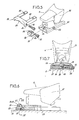
- FIGS 5 to 7 show the mounting method of the heel 4 on the ski 2.
- the heel body 22 is mounted, so known per se, on a slide 23 with the possibility of adjusting its position on the slide using a screw 24 opening into its rear face.
- the heel is fixed to the ski by means of a plate 25, of generally rectangular shape, intended to be fixed definitively, centered on the median longitudinal axis of the ski, by screws passing through holes 26 .
- This plate 25 has a recess 27 opening in its lower face and a recess 28 opening in its front part.
- the recess 27 of width greater than that of the slide 23 serves to accommodate the rear part thereof and the longitudinal edges of the latter over part of their length.
- the longitudinal edges of the slide 23 have recesses 29 for the passage of the fixing screws of the plate.
- the recess 28 is used for the passage of the rear part of the body of the heel piece.
- the rear end of the heel piece is equipped with an end piece 30 which is integral therewith, this end piece comprising a tapped hole 32 oriented transversely to the ski.
- this tapped hole is intended to be engaged a micrometric screw 33 passing through a hole 34 formed in the plate 25, and locked in translation relative to the plate using a pin 35.
- the upper wall of the end piece 30 has a rib 36 intended to be engaged in a corresponding recess 37 formed in the plate.
- a vernier system 31 makes it possible to precisely quantify the value of the lateral displacement of the heel piece.
- two recesses 38 and 39 are provided, facing up and down respectively, formed respectively in the end piece 30 and in the plate 25.
- the recess 39 has a width greater than that of the recess 38, in order to ensure access to the screw 24, whatever the transverse position of the slide 23 and the heel body 22.
- the axis of the shoe forms an angle with the median longitudinal axis of the ski.
- FIGS 8 to 10 show another embodiment of this attachment, in the case of a central plate type attachment.
- This binding has, in a manner known per se, a plate 40 intended to be fitted inside a recess 42 opening into the underside of a shoe sole, the plate 40 and the shoe sole being equipped complementary assembly means 43.
- this binding comprises a plate 44 mounted centrally on the median longitudinal axis of the ski and fixed permanently to the latter by screws passing through holes 45.
- this plate 44 In the lower face of this plate 44 opens a recess 46 of rectangular shape, the upper wall of this plate having for its part an opening 47.
- a housing 48 also of rectangular shape, of width different from that of the recess and of length corresponding to that of the recess, so that its front and rear edges can bear on the front and rear edges of the recess which thus serve as a guide surface.
- a micrometric screw 49 which is blocked in translation, but free to rotate, accessible from the outside of the plate and which meshes with a rack 50 secured to the plate. The actuation of this screw makes it possible to carry out a transverse adjustment of the housing 48 inside the plate 44.
- the column 53 is pivotally mounted opposite of the housing 48, its lower end 52 being shaped as a toothed wheel section 54 with which meshes a screw 55 mounted free in rotation in the housing, but locked in translation therein.
- the actuation of this screw 55 is done from the outside through an orifice 56 formed in the plate.
- the invention provides a great improvement to the existing technique by providing means for attaching a boot to a ski, which are permanently mounted on the ski while offering the possibility of lateral adjustment. and / or instantaneous and continuous angular position of the boot relative to the median longitudinal axis of the ski.
- This adjustment makes it possible, while having a traditional ski with rib lines substantially symmetrical with respect to its median longitudinal axis, to modify behavior parameters of the ski by artificial modification of the effect of the dimension lines and of the divergence of the skiing, taking into account the skier's abilities and morphology, the nature of the snow and the profile of the terrain encountered.
Landscapes
- Footwear And Its Accessory, Manufacturing Method And Apparatuses (AREA)
- Outer Garments And Coats (AREA)
Priority Applications (1)
| Application Number | Priority Date | Filing Date | Title |
|---|---|---|---|
| AT89420131T ATE89758T1 (de) | 1988-04-12 | 1989-04-11 | Befestigungsvorrichtung von schuhen auf skiern. |
Applications Claiming Priority (2)
| Application Number | Priority Date | Filing Date | Title |
|---|---|---|---|
| FR8805252A FR2629728B1 (fr) | 1988-04-12 | 1988-04-12 | Moyens de fixation d'une chaussure sur un ski alpin |
| FR8805252 | 1988-04-12 |
Publications (3)
| Publication Number | Publication Date |
|---|---|
| EP0337905A2 true EP0337905A2 (de) | 1989-10-18 |
| EP0337905A3 EP0337905A3 (en) | 1990-03-21 |
| EP0337905B1 EP0337905B1 (de) | 1993-05-26 |
Family
ID=9365506
Family Applications (1)
| Application Number | Title | Priority Date | Filing Date |
|---|---|---|---|
| EP89420131A Expired - Lifetime EP0337905B1 (de) | 1988-04-12 | 1989-04-11 | Befestigungsvorrichtung von Schuhen auf Skiern |
Country Status (5)
| Country | Link |
|---|---|
| US (1) | US5118128A (de) |
| EP (1) | EP0337905B1 (de) |
| AT (1) | ATE89758T1 (de) |
| DE (1) | DE68906709T2 (de) |
| FR (1) | FR2629728B1 (de) |
Cited By (7)
| Publication number | Priority date | Publication date | Assignee | Title |
|---|---|---|---|---|
| FR2654351A1 (en) * | 1989-11-13 | 1991-05-17 | Rossignol Sa | Ski binding with pivoting plate |
| EP0707872A1 (de) * | 1994-10-19 | 1996-04-24 | TECNICA SpA | Einstellbare Tragplatte für Skibindungen |
| WO1996037270A3 (en) * | 1995-05-26 | 1997-04-17 | Macpod Enterprises Ltd | Connection system for sports footwear |
| EP1754522A3 (de) * | 2005-08-18 | 2007-11-14 | MARKER Deutschland GmbH | Bindungsanordnung für Schneegleitbretter |
| US8201836B2 (en) | 2008-02-29 | 2012-06-19 | Atomic Austria Gmbh | Toe binding of a safety ski binding |
| AT513961A1 (de) * | 2013-02-14 | 2014-08-15 | Tyrolia Technology Gmbh | Vorderbacken |
| FR3109096A1 (fr) * | 2020-04-10 | 2021-10-15 | Skis Rossignol | Butee de fixation de securite de ski, et ski equipe d’une telle butee de fixation |
Families Citing this family (7)
| Publication number | Priority date | Publication date | Assignee | Title |
|---|---|---|---|---|
| ATE123233T1 (de) * | 1989-12-15 | 1995-06-15 | Salomon Sa | Sicherheitsskibindung. |
| FR2684888B1 (fr) * | 1991-12-13 | 1994-02-04 | Salomon Sa | Plaquette interface pour la glissiere d'un element mobile, notamment d'un element de fixation alpine. |
| US5474322A (en) * | 1994-07-21 | 1995-12-12 | Crush Snowboard Products, Inc. | Snowboard binding |
| US6178665B1 (en) | 1997-06-12 | 2001-01-30 | Macpod Enterprises Ltd. | Fit and support system for the foot |
| DE10037503C2 (de) * | 2000-08-01 | 2002-10-17 | Werner Dorsch | An einem Gleitgerät verankerbare Halteeinrichtung für einen Schuh |
| FR2837716B1 (fr) * | 2002-03-27 | 2004-05-14 | Rossignol Sa | Dispositif d'appui pour un element de fixation et planche de glisse sur neige ainsi equipee |
| WO2005031355A1 (en) * | 2003-09-22 | 2005-04-07 | Quidel Corporation | Devices for the detection of multiple analytes in a sample |
Family Cites Families (13)
| Publication number | Priority date | Publication date | Assignee | Title |
|---|---|---|---|---|
| CH86038A (de) * | 1919-12-18 | 1920-08-02 | Krain Adolf | Schneeschuhbindung. |
| FR1217631A (fr) * | 1957-08-22 | 1960-05-04 | Dispositif de fixation perfectionné pour skis | |
| FR1307982A (fr) * | 1961-09-16 | 1962-11-03 | Perfectionnement aux butées de sécurité pour skis | |
| FR1464104A (fr) * | 1965-11-18 | 1966-07-22 | Fixation de ski | |
| US3702194A (en) * | 1970-01-12 | 1972-11-07 | Hope Kk | Sliding device for ski heel binding |
| DE2035803A1 (de) * | 1970-07-18 | 1972-01-27 | Biermann, Peter, Dr , 8100 Garmisch Partenkirchen | Vorderbacken fur Sicherheits Ski bindungen |
| FR2270912A1 (de) * | 1973-11-16 | 1975-12-12 | Mitchell Sa | |
| US3934893A (en) * | 1974-10-04 | 1976-01-27 | Greenleaf Joseph A | Slalom ski device |
| US4141570A (en) * | 1977-10-17 | 1979-02-27 | Sudmeier James L | Adjustable connection between ski and binding |
| FR2546071B1 (fr) * | 1983-05-16 | 1986-04-11 | Salomon Sa | Fixation de securite pour ski |
| FR2560776B1 (fr) * | 1984-03-09 | 1986-09-12 | Salomon Sa | Fixation de securite pour ski a machoire reglable |
| FR2575660A1 (fr) * | 1985-01-09 | 1986-07-11 | Bunand Fabrice | Planche a neige ou " surf " avec un etrier avant reglable et mini-ski desolidarisable |
| DE3540428C2 (de) * | 1985-05-22 | 1996-01-18 | Anton Plenk | Langlaufski |
-
1988
- 1988-04-12 FR FR8805252A patent/FR2629728B1/fr not_active Expired - Lifetime
-
1989
- 1989-04-10 US US07/335,800 patent/US5118128A/en not_active Expired - Fee Related
- 1989-04-11 EP EP89420131A patent/EP0337905B1/de not_active Expired - Lifetime
- 1989-04-11 AT AT89420131T patent/ATE89758T1/de not_active IP Right Cessation
- 1989-04-11 DE DE8989420131T patent/DE68906709T2/de not_active Expired - Fee Related
Cited By (9)
| Publication number | Priority date | Publication date | Assignee | Title |
|---|---|---|---|---|
| FR2654351A1 (en) * | 1989-11-13 | 1991-05-17 | Rossignol Sa | Ski binding with pivoting plate |
| EP0707872A1 (de) * | 1994-10-19 | 1996-04-24 | TECNICA SpA | Einstellbare Tragplatte für Skibindungen |
| US5765852A (en) * | 1994-10-19 | 1998-06-16 | Tecnica Spa | Directional or adjusting plate for ski-boots |
| WO1996037270A3 (en) * | 1995-05-26 | 1997-04-17 | Macpod Enterprises Ltd | Connection system for sports footwear |
| EP1754522A3 (de) * | 2005-08-18 | 2007-11-14 | MARKER Deutschland GmbH | Bindungsanordnung für Schneegleitbretter |
| US8201836B2 (en) | 2008-02-29 | 2012-06-19 | Atomic Austria Gmbh | Toe binding of a safety ski binding |
| AT506526B1 (de) * | 2008-02-29 | 2012-07-15 | Atomic Austria Gmbh | Vorderbacken einer sicherheitsschibindung |
| AT513961A1 (de) * | 2013-02-14 | 2014-08-15 | Tyrolia Technology Gmbh | Vorderbacken |
| FR3109096A1 (fr) * | 2020-04-10 | 2021-10-15 | Skis Rossignol | Butee de fixation de securite de ski, et ski equipe d’une telle butee de fixation |
Also Published As
| Publication number | Publication date |
|---|---|
| US5118128A (en) | 1992-06-02 |
| FR2629728B1 (fr) | 1991-02-08 |
| DE68906709D1 (de) | 1993-07-01 |
| FR2629728A1 (fr) | 1989-10-13 |
| EP0337905B1 (de) | 1993-05-26 |
| EP0337905A3 (en) | 1990-03-21 |
| ATE89758T1 (de) | 1993-06-15 |
| DE68906709T2 (de) | 1993-09-16 |
Similar Documents
| Publication | Publication Date | Title |
|---|---|---|
| EP0337905B1 (de) | Befestigungsvorrichtung von Schuhen auf Skiern | |
| EP0325546B1 (de) | Schneesurf | |
| EP0012097B1 (de) | Sicherheitspedal mit einer fussbetätigten Verriegelungsvorrichtung | |
| EP0838248B1 (de) | Schuhrückhaltevorrichtung auf einem Snowboard | |
| FR2859109A1 (fr) | Dispositif de maintien d'un pied ou d'une chaussure sur un engin de sport | |
| FR2767486A1 (fr) | Dispositif de retenue d'une chaussure sur une planche de glisse destinee a la pratique du surf sur neige | |
| EP0637981B1 (de) | Snowboard | |
| FR2865658A1 (fr) | Dispositif d'accueil d'un pied ou d'une chaussure sur un engin de sport | |
| FR2684885A1 (fr) | Dispositif visant a repartir la pression d'un ski sur une surface de glisse. | |
| EP1166834B1 (de) | Alpinski | |
| EP0398794A1 (de) | Verstellbare Schuhbindung für Wintersport | |
| EP2617475A1 (de) | Taillierung eines Gleitbretts | |
| CA2759086A1 (fr) | Article de sport avec guide chaussure | |
| EP1234604A1 (de) | Trägerplatte für ein Snowboard | |
| EP1013316A1 (de) | Alpinski | |
| FR2674444A1 (fr) | Cales interface pour fixation de securite de ski alpin. | |
| FR2695902A1 (fr) | Dispositif de fixation pour fixer de manière détachable une chaussure à une pédale de cycle. | |
| FR2727029A1 (fr) | Ensemble d'elements de retenue de chaussures sur des planches de glisse | |
| FR2525908A1 (fr) | Dispositifs de fixation de l'avant d'une chaussure a un ski de fond et paire de skis equipee de tels dispositifs | |
| FR2659023A1 (fr) | Surf a neige. | |
| FR2666201A1 (fr) | Chaussure de sport, notamment pour la pratique du ski de fond. | |
| EP3708230B1 (de) | Haltevorrichtung für gleitbrette | |
| FR2769239A1 (fr) | Dispositif de retenue d'une chaussure sur une planche de glisse destinee a la pratique du surf sur neige | |
| FR2886168A1 (fr) | Planche de surf des neiges | |
| WO1994011071A1 (fr) | Dispositif de fixation pour planche de ski surf |
Legal Events
| Date | Code | Title | Description |
|---|---|---|---|
| PUAI | Public reference made under article 153(3) epc to a published international application that has entered the european phase |
Free format text: ORIGINAL CODE: 0009012 |
|
| AK | Designated contracting states |
Kind code of ref document: A2 Designated state(s): AT CH DE ES FR IT LI SE |
|
| PUAL | Search report despatched |
Free format text: ORIGINAL CODE: 0009013 |
|
| AK | Designated contracting states |
Kind code of ref document: A3 Designated state(s): AT CH DE ES FR IT LI SE |
|
| 17P | Request for examination filed |
Effective date: 19900414 |
|
| 17Q | First examination report despatched |
Effective date: 19910710 |
|
| GRAA | (expected) grant |
Free format text: ORIGINAL CODE: 0009210 |
|
| AK | Designated contracting states |
Kind code of ref document: B1 Designated state(s): AT CH DE ES FR IT LI SE |
|
| PG25 | Lapsed in a contracting state [announced via postgrant information from national office to epo] |
Ref country code: IT Free format text: LAPSE BECAUSE OF FAILURE TO SUBMIT A TRANSLATION OF THE DESCRIPTION OR TO PAY THE FEE WITHIN THE PRESCRIBED TIME-LIMIT;WARNING: LAPSES OF ITALIAN PATENTS WITH EFFECTIVE DATE BEFORE 2007 MAY HAVE OCCURRED AT ANY TIME BEFORE 2007. THE CORRECT EFFECTIVE DATE MAY BE DIFFERENT FROM THE ONE RECORDED. Effective date: 19930526 Ref country code: ES Free format text: THE PATENT HAS BEEN ANNULLED BY A DECISION OF A NATIONAL AUTHORITY Effective date: 19930526 Ref country code: SE Effective date: 19930526 |
|
| REF | Corresponds to: |
Ref document number: 89758 Country of ref document: AT Date of ref document: 19930615 Kind code of ref document: T |
|
| REF | Corresponds to: |
Ref document number: 68906709 Country of ref document: DE Date of ref document: 19930701 |
|
| PLBE | No opposition filed within time limit |
Free format text: ORIGINAL CODE: 0009261 |
|
| STAA | Information on the status of an ep patent application or granted ep patent |
Free format text: STATUS: NO OPPOSITION FILED WITHIN TIME LIMIT |
|
| PG25 | Lapsed in a contracting state [announced via postgrant information from national office to epo] |
Ref country code: CH Effective date: 19940430 Ref country code: LI Effective date: 19940430 |
|
| 26N | No opposition filed | ||
| REG | Reference to a national code |
Ref country code: CH Ref legal event code: PL |
|
| PGFP | Annual fee paid to national office [announced via postgrant information from national office to epo] |
Ref country code: AT Payment date: 19980302 Year of fee payment: 10 |
|
| PGFP | Annual fee paid to national office [announced via postgrant information from national office to epo] |
Ref country code: DE Payment date: 19980430 Year of fee payment: 10 |
|
| PG25 | Lapsed in a contracting state [announced via postgrant information from national office to epo] |
Ref country code: AT Free format text: LAPSE BECAUSE OF NON-PAYMENT OF DUE FEES Effective date: 19990411 |
|
| PG25 | Lapsed in a contracting state [announced via postgrant information from national office to epo] |
Ref country code: DE Free format text: LAPSE BECAUSE OF NON-PAYMENT OF DUE FEES Effective date: 20000201 |
|
| PGFP | Annual fee paid to national office [announced via postgrant information from national office to epo] |
Ref country code: FR Payment date: 20060117 Year of fee payment: 18 |
|
| PG25 | Lapsed in a contracting state [announced via postgrant information from national office to epo] |
Ref country code: FR Free format text: LAPSE BECAUSE OF NON-PAYMENT OF DUE FEES Effective date: 20070430 |