EP0337718A2 - Behälter für Kontaktlinsen - Google Patents
Behälter für Kontaktlinsen Download PDFInfo
- Publication number
- EP0337718A2 EP0337718A2 EP89303546A EP89303546A EP0337718A2 EP 0337718 A2 EP0337718 A2 EP 0337718A2 EP 89303546 A EP89303546 A EP 89303546A EP 89303546 A EP89303546 A EP 89303546A EP 0337718 A2 EP0337718 A2 EP 0337718A2
- Authority
- EP
- European Patent Office
- Prior art keywords
- lens
- canister
- cap
- receptacles
- retaining portion
- Prior art date
- Legal status (The legal status is an assumption and is not a legal conclusion. Google has not performed a legal analysis and makes no representation as to the accuracy of the status listed.)
- Withdrawn
Links
Images


Classifications
-
- A—HUMAN NECESSITIES
- A61—MEDICAL OR VETERINARY SCIENCE; HYGIENE
- A61L—METHODS OR APPARATUS FOR STERILISING MATERIALS OR OBJECTS IN GENERAL; DISINFECTION, STERILISATION OR DEODORISATION OF AIR; CHEMICAL ASPECTS OF BANDAGES, DRESSINGS, ABSORBENT PADS OR SURGICAL ARTICLES; MATERIALS FOR BANDAGES, DRESSINGS, ABSORBENT PADS OR SURGICAL ARTICLES
- A61L12/00—Methods or apparatus for disinfecting or sterilising contact lenses; Accessories therefor
- A61L12/08—Methods or apparatus for disinfecting or sterilising contact lenses; Accessories therefor using chemical substances
- A61L12/086—Container, accessories or devices therefor
-
- A—HUMAN NECESSITIES
- A45—HAND OR TRAVELLING ARTICLES
- A45C—PURSES; LUGGAGE; HAND CARRIED BAGS
- A45C11/00—Receptacles for purposes not provided for in groups A45C1/00-A45C9/00
- A45C11/005—Contact lens cases
-
- Y—GENERAL TAGGING OF NEW TECHNOLOGICAL DEVELOPMENTS; GENERAL TAGGING OF CROSS-SECTIONAL TECHNOLOGIES SPANNING OVER SEVERAL SECTIONS OF THE IPC; TECHNICAL SUBJECTS COVERED BY FORMER USPC CROSS-REFERENCE ART COLLECTIONS [XRACs] AND DIGESTS
- Y10—TECHNICAL SUBJECTS COVERED BY FORMER USPC
- Y10S—TECHNICAL SUBJECTS COVERED BY FORMER USPC CROSS-REFERENCE ART COLLECTIONS [XRACs] AND DIGESTS
- Y10S134/00—Cleaning and liquid contact with solids
- Y10S134/901—Contact lens
Definitions
- the present invention relates generally to a contact lens case and, more particularly, to such a case which can be used to store both hard and soft contact lenses as well as to clean and rinse the lenses while in the case.
- Hard contact lenses must be stored in enclosures or storage cases when not in use.
- Hard contact lenses should, preferably, be stored in an immersion fluid which acts to both clean the lenses and serves as an asepticizing agent to prevent the growth of undesirable organisms on the lens surfaces.
- soft contact lenses With soft contact lenses, there is even a greater requirement that the lenses be stored in an immersion fluid since such lenses are porous in nature and susceptible to drying out if not hydrated. Further, soft contact lenses must be periodically sterilized and cleaned to remove secretions from the eye and to prevent the growth of bacteria and the like on the lenses.
- Sterilization of soft contact lenses is typically accomplished by immersion of the lenses in sterilizing chemicals or by heating the lenses while immersed in a saline solution.
- lens cleaning may be accomplished either manually, i.e, physically rubbing the lenses with a cleaning fluid, or by insertion of the lenses into the type of contact lens storage case which includes mechanical cleaning means and then cleaning the lenses while in such a case.
- U.S. Patent No. 3,997,049 which issued on December 14, 1976 to G.J. Sherman, teaches an Enclosure For Hard And Soft Contact Lenses which includes a pair of lens retaining baskets contained within an enclosure.
- the baskets are pivotably mounted to the cap of the container so that when the cap is removed from the enclosure, the baskets may be folded outwardly to allow unimpaired access to the lenses in the baskets, and when the cap is secured on the enclosure, the baskets can rotate within the enclosure causing agitation of the fluid to enhance cleaning of the lenses in the baskets.
- the baskets are rotated in a single rotational plane around the case and the resultant agitation serves to enhance cleaning of the lenses. While such agitation effectively removes normal eye secretions and the like from the lenses, it is not particularly effective in removing more resistant residues. It has been found, however, that if the baskets are simultaneously moved in multiple planes, i.e, in a rotational direction around the circumference of the case as well as oscillated in a direction toward and away from their axis of rotation, the agitation of the cleaning or washing solution is substantially increased with an attendant increase in lens cleaning.
- the present invention in brief summary, comprises a contact lens case which includes a canister open at its upper end for receiving lens contact lens rinsing or cleansing fluid and a cap adapted to be secured to and seal the canister.
- the cap includes a securing ring which is adapted to engage complementary securing means on the canister.
- the cap of the contact lens case further includes a lens retaining portion having at least two lens receptacles pivotably mounted on a shoulder.
- a leaf spring is provided in the shoulder for urging the lens receptacles apart.
- the cap further includes a turning knob which is connected to a planetary gear mechanism for causing the lens retaining portion to rotate in the canister as the turning knob on the cap is rotated.
- each lens receptacle Downwardly extending finger means are provided on each lens receptacle and are adapted to engage a complementary, elliptically shaped, track at the base of the inner surface of the canister to cause the lens receptacles to be simultaneously oscillated toward and away from the axis of rotation of the lens retaining portion as the lens receptacle portion is rotated about the circumference of the canister.
- a contact lens case including: a canister, open at its top end, for receiving contact lens fluid; and a cap including: a securing ring for securing the cap to said canister; a lens retaining portion including at least two perforated lens receptacles, each adapted to receive and store a contact lens; rotational means for causing the lens retaining portion to rotate within said canister about an axis of rotation; and oscillating means for causing each of said lens receptacles to be oscillated toward and away from the axis of rotation of said lens retaining portion as said lens retaining portion is rotated about said axis of rotation within said canister.
- a contact lens case including: a canister, open at its top, for receiving contact lens fluid; and a cap including: a securing ring adapted to secure said cap to said canister; a lens retaining portion including at least two lens foraminous receptacles, each of said lens receptacles being adapted to receive and store a contact lens; transfer means connected to said lens retaining portions; a turning knob provided on said cap and a planetary gear mechanism connected to said cap, said planetary gear mechanism being adapted to transfer by said transfer means the rotation of said turning knob to said lens retaining portion for causing said lens retaining portion to rotate about an axis of rotation in said canister; and oscillating means for causing each of said lens receptacles to be simultaneously oscillated toward and away from the axis of rotation of said lens receptacle portion as said lens retaining portion is rotated within said canister.
- a contact lens case including: a canister, open at its top, for receiving lens washing fluid, and having an elliptically shaped track in the base of the inner portion thereof; and a cap including: a securing ring adapted to threadably engage said canister so as to secure said cap to said canister; a lens retaining portion including at least two lens receptacles pivotably mounted on a shoulder, said shoulder including a spring for biasing said lens receptacles in a direction away from said shoulder; a turning knob provided on said cap and a planetary gear mechanism connected to said cap, said planetary gear mechanism being adapted to cause said lens retaining portion to rotate as said turning knob is rotated; and oscillating means comprising at least one finger member extending downwardly from each of said lens receptacles, said finger members being adapted to engage and travel within said elliptically shaped track in said canister, wherein said oscillating means causes each of the lens recepta
- a contact lens case including: a canister, open at its top, for receiving lens washing fluid, and having a pre-defined pathway in the base of the inner portion thereof; and a cap including: a securing ring adapted to threadably engage said canister so as to secure said cap to said canister; a lens retaining portion including at least two lens receptacles pivotably mounted on a shoulder, a turning knob provided on said cap and a planetary gear mechanism connected to said cap, said planetary gear mechanism being adapted to cause said lens retaining portion to rotate as said turning knob is rotated; and oscillating means comprising at least one finger member extending downwardly from each of said lens receptacles, said finger members being adapted to engage and travel within said pathway in said canister, wherein said oscillating means causes each of the lens receptacles to be oscillated toward and away from the axis of rotation of said lens retaining portion as said lens retaining portion is simultaneously rotated about the circum
- a contact lens case including: a canister, open at its top, for receiving lens washing fluid, and having a track in the base of the inner portion thereof; and a cap including: a securing ring adapted to threadably engage said canister so as to secure said cap to said canister; a lens retaining portion including at least two lens receptacles pivotably mounted on a shoulder, a turning knob provided on said cap and a planetary gear mechanism connected to said cap, said planetary gear mechanism being adapted to cause said lens retaining portion to rotate as said turning knob is rotated; and oscillating means comprising at least one finger member extending downwardly from each of said lens receptacles and means for spring biasing said lens receptacles toward one another and said finger members into said track, wherein said oscillating means causes each of the lens receptacles to be oscillated toward and away from the axis of rotation of said lens retaining portion as said lens retaining portion is simultaneously rotated
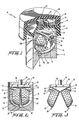
- the contact lens case of the present invention includes a cap 12 adapted to threadably engage and seal with a canister 14 to form the case 10.
- the cap 12 includes an internally threaded, securing ring 22 which is adapted to engage complementary external threads on the upper portion of the canister 14 to secure and seal the cap 12 to the canister 14.
- a gasket 23 is provided in the securing ring 22 for securely sealing the cap 12 to the canister 14 to prevent contact lens washing or rinsing fluid from leaking from the case 10 during use.
- a turning knob 20 is provided on the cap 12 and is adapted to be rotatably mounted relative to the securing ring 22. Through a planetary gear mechanism 24, the turning knob 20 is adapted to transfer its rotary motion to a lens retaining portion 25 which includes a pair of perforated, basket-type, lens receptacles 30, each of which is adapted to receive and store a contact lens.
- the planetary gear mechanism 24 is similar to the mechanism described in U.S. Patent No. 3,623,492, the disclosure of which is hereby incorporated herein by reference.
- Internal teeth 29 are provided on the inner surface of the turning knob 20 and are adapted to engage and cause to rotate a planetary gear 28 which is, likewise, adapted to engage and cause to rotate a spur gear 27 which is attached to the upper end of a trunnion rod 26.
- a lens retaining portion 25 including a pair of perforated basket-type, lens receptacles 30 is mounted on the opposite end of the trunnion rod 26 and is suspended within the case 10 when the cap 12 is secured to the canister 14.
- the planetary gear mechanism 24 causes the lens retaining portion 25 suspended within the canister 14 to correspondingly rotate about the canister 14.
- Each of the pair of foraminous or perforated, basket-type, lens receptacles 30 has a hinge element 32 which is pivotably mounted at pivot point 33 to a complementary hinge arm 35 on the shoulder 34.
- Each of the lens receptacles 30 includes a pair of perforated covers 30A adapted to receive and positively retain therein at least one contact lens and latch means 30B for securing the perforated covers 30A to the lens receptacles 30.
- Each lens receptacle 30 and the pair of covers 30A for each receptacle 30 is similar to the receptacles or baskets described in U.S. Patent No. 3,997,049, the disclosure of which is hereby incorporated by reference thereto, in that the pair of covers can be contoured so that one has a generally convex body and the other has a planar body thereby forming a composite structure having a generally spherical shape adapted to receive a complementary configured contact lens. Further, the lens receptacles 30 are adapted to fold toward and away from each other when the lens is removed from the receptacle 30 to allow easy access to the lens in each receptacle 30.
- a finger 36 is provided at the lower end of each lens receptacle 30.
- the finger 36 may be integrally formed with the respective lens receptacle 30 or it may be a plastic or metal finger or a clip which is secured to the lens receptacles 30.
- the fingers 36 preferably extended outwardly from the covers 30A.
- the fingers 36 are adapted to be inserted into and travel within a predefined track 45 provided at the base of the inner surface or wall 15 of the canister 14.
- the track 45 as shown in FIG. 6, may be elliptical or spherical in shape.
- a leaf spring 40 is provided between the hinge arms 35 of the shoulder 34.
- the leaf spring 40 has a bend in its center portion 41 so that the legs 42 of the spring 40 biases in a downward direction with respect to the shoulder 34.
- the leaf spring 40 is adapted to apply downward pressure against the lens receptacles 30, thus serving to urge the finger 36 of each receptacle 30 shown in Fig. 3 against the outer edge or circumference of the track 45 provided at the base of the inner surface 15 of the canister 14 shown in Fig. 6 thereby permitting lens receptacles 30 to oscillate as the turning knob 20 is turned.
- the leaf spring 45 also serves to urge the lens receptacles 30 apart when the lens retaining portion 25 is removed from the canister 14 to facilitate access to the contact lenses being stored therein.
- the hinge arms 135 of the shoulder 134 may, in an alternative embodiment, be modified by pre-casting the arms 135 with a slight upward curve. Cut-outs 136 permit the hinge arms 135 and shoulder 134 to be able to deflect or bend, thus eliminating the need for the incorporation of a leaf spring 40 as provided in the embodiment of FIG. 5.
- the canister forces the two receptacles together so that shoulder 134 is at cut-outs 136 bent downward from its curved, natural position to a horizontal position as shown by dotted lines 134′ in Fig.
- the finger 36 of each receptacle 30 enter into predefined track 45 provided at the base of canister 14 as shown in Fig. 2.
- the natural bias of shoulder 134 causes it to revert back to its curved or bowed position so as to provide the force that causes the finger 36 of each receptacle 30 to follow the predefined track 45 provided at the base of the inner surface 15 of the canister 14.
- the lens case 10 operates in the following manner.
- the lens case 10 is opened by disengaging the securing ring 22 from the canister 14 thus permitting access to the lens retaining portion 25.
- the leaf spring 40 urges the individual lens receptacles 30 apart to facilitate access to the individual receptacles and to permit contact lenses to be introduced into the proper receptacle 30.
- the lenses are retained in the lens receptacles 30 by engaging the respective covers 30A to the receptacles 30 by latch means 30B.
- Lens cleaning or rinsing fluid is then added to the canister 14 and the cap 12 is re-secured to the canister 14 by engaging securing ring 22.
- the fingers 36 at the bottom of the lens receptacles 30 are urged by the action of leaf spring 40 into the track 45 at the base of the inner surface 15 of the canister 14.
- Cleaning or rinsing of the contact lenses contained within the lens receptacles 30 is effected by rotation of the turning knob 20 which causes the lens retaining portion 25 including the lens receptacles 30 to rotate about the canister 14.
- the lens receptacles 30 are simultaneously oscillated toward and away from one another and their normal axis of rotation as the lens receptacles 30 rotate about the canister 14 and as the fingers 36 travel within the oval track 45, due to the following factors: the retention of the fingers 36 within the track 45 at the base of the inner surface 15 of the canister 14, the elliptical or oval shape of the track 45, and the action of the leaf spring 40 which biases the fingers 36 in an outward direction.
- the cleaning or rinsing fluid becomes agitated and is forced through the perforations in the lens receptacles 30. This action effects a thorough cleaning of the contact lenses captured therein due to the fact that fluid is forced against the front and back surfaces of the lenses.
- FIGS. 8-9 illustrate an alternative embodiment in which track 145 is provided on the base of the inner surface 115 of a canister 114.
- the lens receptacles 130 are simultaneously oscillated toward and away from one another and their normal axis of rotation as the fingers 136 travel within the track 145.
- the track 145 is only sufficiently wide to accommodate the finger 136 and, as such, oscillation is accomplished as the fingers 136 travel around track 145.
- a leaf spring 40 as used in the embodiment of FIGS. 1-6 to urge the fingers against the outer edges of the track 45.
- the fingers 136 of the embodiment of FIGS. 8-9 can be spring loaded to simultaneously force the individual lens receptacles 130 together as they travel about the track 145.
Landscapes
- Health & Medical Sciences (AREA)
- Animal Behavior & Ethology (AREA)
- General Chemical & Material Sciences (AREA)
- Chemical Kinetics & Catalysis (AREA)
- Epidemiology (AREA)
- Life Sciences & Earth Sciences (AREA)
- Chemical & Material Sciences (AREA)
- General Health & Medical Sciences (AREA)
- Public Health (AREA)
- Veterinary Medicine (AREA)
- Purses, Travelling Bags, Baskets, Or Suitcases (AREA)
- Eyeglasses (AREA)
- Lens Barrels (AREA)
Applications Claiming Priority (2)
| Application Number | Priority Date | Filing Date | Title |
|---|---|---|---|
| US07/179,799 US4826001A (en) | 1988-04-11 | 1988-04-11 | Contact lens case |
| US179799 | 1988-04-11 |
Publications (2)
| Publication Number | Publication Date |
|---|---|
| EP0337718A2 true EP0337718A2 (de) | 1989-10-18 |
| EP0337718A3 EP0337718A3 (de) | 1990-10-17 |
Family
ID=22658053
Family Applications (1)
| Application Number | Title | Priority Date | Filing Date |
|---|---|---|---|
| EP19890303546 Withdrawn EP0337718A3 (de) | 1988-04-11 | 1989-04-11 | Behälter für Kontaktlinsen |
Country Status (4)
| Country | Link |
|---|---|
| US (1) | US4826001A (de) |
| EP (1) | EP0337718A3 (de) |
| JP (1) | JP2768972B2 (de) |
| CA (1) | CA1321778C (de) |
Cited By (1)
| Publication number | Priority date | Publication date | Assignee | Title |
|---|---|---|---|---|
| CN113768267A (zh) * | 2021-09-10 | 2021-12-10 | 沛县亨得利眼镜有限公司 | 一种智能化眼镜盒 |
Families Citing this family (12)
| Publication number | Priority date | Publication date | Assignee | Title |
|---|---|---|---|---|
| CH675492A5 (de) * | 1988-03-29 | 1990-09-28 | Essilor Int | |
| US5114686A (en) * | 1989-03-16 | 1992-05-19 | Ciba-Geigy Corporation | Contact lens disinfection unit with invertible lens holding baskets |
| US4890729A (en) * | 1989-04-25 | 1990-01-02 | Ryder International Corporation | Lens retaining apparatus |
| US5196174A (en) * | 1989-06-09 | 1993-03-23 | Ciba Vision Corporation | Apparatus for sterilizing contact lenses |
| US5167323A (en) * | 1990-08-09 | 1992-12-01 | Tomei Sangyo Co., Ltd. | Lens treating device for treating contact lens |
| US5181604A (en) * | 1990-09-14 | 1993-01-26 | Tomei Sangyo Co., Ltd. | Contact lens holder and treating device |
| GR920100472A (el) * | 1992-10-20 | 1994-06-30 | Nektarios Kissandrakis | Θήκη φακών επαφής με σύστημα επιφανειακού κα?αρισμού. |
| US5456276A (en) * | 1994-12-30 | 1995-10-10 | Shun-Hsien; Wang | Contact lens cleaning apparatus |
| USD452611S1 (en) | 1999-12-21 | 2002-01-01 | Stacey A. Redgrave | Contact lens storage case with keychain |
| KR20020073965A (ko) * | 2001-03-17 | 2002-09-28 | 조한주 | 원심력을 이용한 휴대용 소프트 렌즈 세척기 |
| US20050045495A1 (en) * | 2003-08-25 | 2005-03-03 | Dalsing Troy A. | Reusable container for contact lenses and other materials |
| CN101024225B (zh) * | 2006-02-17 | 2011-06-22 | 鸿富锦精密工业(深圳)有限公司 | 清洗治具及清洗方法 |
Family Cites Families (10)
| Publication number | Priority date | Publication date | Assignee | Title |
|---|---|---|---|---|
| US3379200A (en) * | 1965-10-24 | 1968-04-23 | Ruth M. Pennell | Lens containtr |
| US3378020A (en) * | 1967-04-24 | 1968-04-16 | Richard H. Grabiel | Container for contact lenses |
| US3623492A (en) * | 1969-09-24 | 1971-11-30 | Dolph G Frantz | Contact lens washer with lens storage |
| US4002234A (en) * | 1975-01-29 | 1977-01-11 | Wesley-Jessen Inc. | Contact lens container |
| US4011941A (en) * | 1975-04-28 | 1977-03-15 | Warner-Lambert Company | Contact lens capsule |
| US3997049A (en) * | 1975-09-04 | 1976-12-14 | Milton Roy Company | Enclosure for hard and soft contact lenses |
| US4009777A (en) * | 1975-12-29 | 1977-03-01 | Ryder International Corporation | Contact lens holder |
| US4200187A (en) * | 1978-10-27 | 1980-04-29 | Ryder International Corporation | Lens case with oppositely hinged baskets |
| US4396583A (en) * | 1981-08-14 | 1983-08-02 | American Optical Corporation | Device for single solution contact lens sterilization |
| US4653519A (en) * | 1985-07-09 | 1987-03-31 | Ryder International Corporation | Rinsing apparatus for contact lens cleaning system |
-
1988
- 1988-04-11 US US07/179,799 patent/US4826001A/en not_active Expired - Lifetime
-
1989
- 1989-03-23 CA CA000594604A patent/CA1321778C/en not_active Expired - Lifetime
- 1989-04-10 JP JP1088199A patent/JP2768972B2/ja not_active Expired - Lifetime
- 1989-04-11 EP EP19890303546 patent/EP0337718A3/de not_active Withdrawn
Cited By (2)
| Publication number | Priority date | Publication date | Assignee | Title |
|---|---|---|---|---|
| CN113768267A (zh) * | 2021-09-10 | 2021-12-10 | 沛县亨得利眼镜有限公司 | 一种智能化眼镜盒 |
| CN113768267B (zh) * | 2021-09-10 | 2022-09-30 | 沛县亨得利眼镜有限公司 | 一种智能化眼镜盒 |
Also Published As
| Publication number | Publication date |
|---|---|
| JPH01293804A (ja) | 1989-11-27 |
| JP2768972B2 (ja) | 1998-06-25 |
| EP0337718A3 (de) | 1990-10-17 |
| US4826001A (en) | 1989-05-02 |
| CA1321778C (en) | 1993-08-31 |
Similar Documents
| Publication | Publication Date | Title |
|---|---|---|
| US4826001A (en) | Contact lens case | |
| US5181604A (en) | Contact lens holder and treating device | |
| JPH02278225A (ja) | 反転可能なレンズ保持バスケットを備えるコンタクトレンズ保持装置 | |
| US3343657A (en) | Contact lens conditioning facility | |
| US4890729A (en) | Lens retaining apparatus | |
| US3990579A (en) | Contact lens holding unit | |
| JPH01113047A (ja) | レンズ容器組立体 | |
| US5186317A (en) | Lens case for contact lens disinfecting system | |
| US20070212277A1 (en) | Medical instrument container system | |
| US3997049A (en) | Enclosure for hard and soft contact lenses | |
| JPH0288067A (ja) | コンタクトレンズ消毒装置 | |
| JP2001046134A (ja) | コンタクトレンズ用保存容器 | |
| RU2731862C2 (ru) | Паровой утюг с отделением для сбора известковых отложений | |
| US20190021473A1 (en) | Orthodontic retainer cleaning case | |
| US6910488B2 (en) | Valve dishwasher basket and soaking container | |
| US4546517A (en) | Wiping device | |
| US3801279A (en) | Cold sterilization unit | |
| US6289907B1 (en) | Device and method for cleaning contact lenses | |
| US3203598A (en) | Controllably openable and closable holder for a disposable liquid container | |
| US5080117A (en) | Device for cleaning contact lenses | |
| JP7633793B2 (ja) | ソフトコンタクトレンズ用収納ケース | |
| JP4086970B2 (ja) | 内視鏡用キャリングケース | |
| KR102403456B1 (ko) | 콘택트렌즈 보관통 | |
| KR19990013146U (ko) | 콘택트렌즈 세척기 | |
| KR200377351Y1 (ko) | 걸이식 콘택트 렌즈 보관 케이스 |
Legal Events
| Date | Code | Title | Description |
|---|---|---|---|
| PUAI | Public reference made under article 153(3) epc to a published international application that has entered the european phase |
Free format text: ORIGINAL CODE: 0009012 |
|
| AK | Designated contracting states |
Kind code of ref document: A2 Designated state(s): BE DE ES FR GB IT NL SE |
|
| RAP1 | Party data changed (applicant data changed or rights of an application transferred) |
Owner name: PILKINGTON VISIONCARE INC. (A DELAWARE CORP.) |
|
| PUAL | Search report despatched |
Free format text: ORIGINAL CODE: 0009013 |
|
| AK | Designated contracting states |
Kind code of ref document: A3 Designated state(s): BE DE ES FR GB IT NL SE |
|
| 17P | Request for examination filed |
Effective date: 19910125 |
|
| 17Q | First examination report despatched |
Effective date: 19920825 |
|
| STAA | Information on the status of an ep patent application or granted ep patent |
Free format text: STATUS: THE APPLICATION IS DEEMED TO BE WITHDRAWN |
|
| 18D | Application deemed to be withdrawn |
Effective date: 19931130 |