EP0337099A2 - Control device for an internal combustion engine in vehicles - Google Patents
Control device for an internal combustion engine in vehicles Download PDFInfo
- Publication number
- EP0337099A2 EP0337099A2 EP19890103735 EP89103735A EP0337099A2 EP 0337099 A2 EP0337099 A2 EP 0337099A2 EP 19890103735 EP19890103735 EP 19890103735 EP 89103735 A EP89103735 A EP 89103735A EP 0337099 A2 EP0337099 A2 EP 0337099A2
- Authority
- EP
- European Patent Office
- Prior art keywords
- throttle valve
- coupling part
- valve shaft
- armature
- coupling
- Prior art date
- Legal status (The legal status is an assumption and is not a legal conclusion. Google has not performed a legal analysis and makes no representation as to the accuracy of the status listed.)
- Withdrawn
Links
Images

Classifications
-
- F—MECHANICAL ENGINEERING; LIGHTING; HEATING; WEAPONS; BLASTING
- F02—COMBUSTION ENGINES; HOT-GAS OR COMBUSTION-PRODUCT ENGINE PLANTS
- F02D—CONTROLLING COMBUSTION ENGINES
- F02D11/00—Arrangements for, or adaptations to, non-automatic engine control initiation means, e.g. operator initiated
- F02D11/06—Arrangements for, or adaptations to, non-automatic engine control initiation means, e.g. operator initiated characterised by non-mechanical control linkages, e.g. fluid control linkages or by control linkages with power drive or assistance
- F02D11/10—Arrangements for, or adaptations to, non-automatic engine control initiation means, e.g. operator initiated characterised by non-mechanical control linkages, e.g. fluid control linkages or by control linkages with power drive or assistance of the electric type
- F02D11/107—Safety-related aspects
-
- F—MECHANICAL ENGINEERING; LIGHTING; HEATING; WEAPONS; BLASTING
- F02—COMBUSTION ENGINES; HOT-GAS OR COMBUSTION-PRODUCT ENGINE PLANTS
- F02D—CONTROLLING COMBUSTION ENGINES
- F02D11/00—Arrangements for, or adaptations to, non-automatic engine control initiation means, e.g. operator initiated
- F02D11/06—Arrangements for, or adaptations to, non-automatic engine control initiation means, e.g. operator initiated characterised by non-mechanical control linkages, e.g. fluid control linkages or by control linkages with power drive or assistance
- F02D11/10—Arrangements for, or adaptations to, non-automatic engine control initiation means, e.g. operator initiated characterised by non-mechanical control linkages, e.g. fluid control linkages or by control linkages with power drive or assistance of the electric type
- F02D2011/101—Arrangements for, or adaptations to, non-automatic engine control initiation means, e.g. operator initiated characterised by non-mechanical control linkages, e.g. fluid control linkages or by control linkages with power drive or assistance of the electric type characterised by the means for actuating the throttles
- F02D2011/103—Arrangements for, or adaptations to, non-automatic engine control initiation means, e.g. operator initiated characterised by non-mechanical control linkages, e.g. fluid control linkages or by control linkages with power drive or assistance of the electric type characterised by the means for actuating the throttles at least one throttle being alternatively mechanically linked to the pedal or moved by an electric actuator
Landscapes
- Engineering & Computer Science (AREA)
- Chemical & Material Sciences (AREA)
- Combustion & Propulsion (AREA)
- Mechanical Engineering (AREA)
- General Engineering & Computer Science (AREA)
- Control Of Throttle Valves Provided In The Intake System Or In The Exhaust System (AREA)
Abstract
Description
Die Erfindung betrifft eine Vorrichtung zur Regelung einer Brennkraftmaschine in Fahrzeugen der im Oberbegriff des Anspruchs 1 definierten Gattung.The invention relates to a device for controlling an internal combustion engine in vehicles of the type defined in the preamble of claim 1.
Mit solchen Vorrichtungen wird die Leistung der Brennkraftmaschine durch Drosselklappenverstellung elektrisch gesteuert. Die Steuerelektronik ist dabei so konzipiert, daß bei Auftreten von gravierenden Fehlern die Steuerung abgeschaltet wird und durch von einer Rückstellfeder erzwungenes Schließen der Drosselklappe die Brennkraftmaschine zum Stillstand kommt. Durch die zusätzliche Notfahreinrichtung wird in solchen Fällen die Manövrierfähigkeit des Fahrzeugs sichergestellt.With such devices, the performance of the internal combustion engine is electrically controlled by throttle valve adjustment. The control electronics are designed in such a way that the control is switched off when serious errors occur and the internal combustion engine comes to a standstill due to the return spring being forced to close the throttle valve. In such cases, the additional emergency equipment ensures that the vehicle is maneuverable.
Bei einer bekannten Vorrichtung dieser Art (DE-PS 36 09 849) ist der Fahrhebel oder das Fahrpedal über einen Bowdenzug mit dem Sollwertgeber gekuppelt und verstellt letzteren entsprechend der Fahrhebelstellung. Die Drehstellung des Sollwertgebers wird als elektrisches Signal an eine Steuerelektronik übertragen, die daraus und unter Berücksichtigung weiterer Regelgrößen, wie den Schlupf der Antriebsräder, ein Stellsignal für den die Drosselklappe schwenkenden Stellmotor generiert.In a known device of this type (DE-PS 36 09 849) the drive lever or the accelerator pedal is via a Bowden cable coupled with the setpoint device and adjusts the latter according to the driving lever position. The rotational position of the setpoint generator is transmitted as an electrical signal to control electronics, which, taking into account further control variables such as the slip of the drive wheels, generates an actuating signal for the servomotor that swivels the throttle valve.
Die Notfahreinrichtung besteht aus einem längenveränderlichen mechanischen Übertragungselement, das als Stange ausgebildet ist und über einen Verbindungshebel mit dem Sollwertgeber verbindbar ist. Der Verbindungshebel ist durch einen Schlepphebel in Richtung Vollast mitschleppbar. Der Schlepphebel verbindet den Fahrhebel mit dem Sollwertgeber. Die Längenveränderlichkeit der Stange wird durch zwei Druckfedern mit unterschiedlicher Vorspannung realisiert. Im Störfall, wenn die elektrische Leistungsregelung ausfällt, wird bei stromlosem Stellmotor bei Betätigung des Fahrhebels der Verbindungshebel vom Schlepphebel so weit mitgeschleppt und damit die Übertragungsstange so weit zusammengedrückt, bis infolge der Federkraft der stärkeren Druckfeder die Drosselklappe verstellt wird. Es ist dann ein Fahrbetrieb mit halber Last der Brennkraftmaschine möglich.The emergency drive device consists of a variable-length mechanical transmission element which is designed as a rod and can be connected to the setpoint device via a connecting lever. The link lever can also be towed towards full load by a rocker arm. The rocker arm connects the drive lever to the setpoint device. The length variability of the rod is realized by two compression springs with different preloads. In the event of a malfunction, when the electrical power control fails, when the actuator is de-energized, when the drive lever is actuated, the connecting lever is dragged along by the rocker arm and thus the transmission rod is compressed until the throttle valve is adjusted due to the spring force of the stronger compression spring. Driving with half the load of the internal combustion engine is then possible.
Nachteilig ist hier, daß im ungestörten Betrieb, z.B. bei Schlupfregelung, der Stellmotor gegen die schwache Druckfeder in der Übertragungsstange arbeiten muß, so daß hier ein zusätzlicher Reibwiderstand auftritt. Handelsübliche Stellmotoren mit ihrer relativ großen Drehmomentempfindlichkeit können daher nicht verwendet werden.The disadvantage here is that in undisturbed operation, for example with slip control, the servomotor must work against the weak compression spring in the transmission rod, so that an additional frictional resistance occurs here. Commercial servomotors with their relatively high sensitivity to torque cannot therefore be used.
Die erfindungsgemäße Vorrichtung mit den kennzeichnenden Merkmalen des Anspruchs 1 hat den Vorteil, daß während des störungsfreien Betriebs der Fahrhebel völlig von der Drosselklappe abgekuppelt ist, so daß für den, an der Drosselklappenwelle angreifenden drehmomentempfindlichen Stellmotor keine zusätzliche Reibung vorhanden ist. Erst im Störungsfall, also wenn der Stellmotor abgeschaltet ist, wird der Fahrhebel selbsttätig und fahrerunabhängig mit der Drosselklappe gekuppelt, und letztere wird bei Betätigung des Fahrhebels im Notfahrbetrieb von diesem mechanisch verstellt.The device according to the invention with the characterizing features of claim 1 has the advantage that during the trouble-free operation of the drive lever is completely uncoupled from the throttle valve, so that there is no additional friction for the torque-sensitive actuator acting on the throttle valve shaft. Only in the event of a malfunction, i.e. when the servomotor is switched off, is the driving lever automatically and driver-independently coupled to the throttle valve, and the latter is mechanically adjusted when the driving lever is actuated in emergency driving mode.
Durch die in den weiteren Ansprüchen aufgeführten Maßnahmen sind vorteilhafte Weiterbildungen und Verbesserungen der im Anspruch 1 angegebenen Vorrichtung möglich.The measures listed in the further claims allow advantageous developments and improvements of the device specified in claim 1.
Bei Ausbildung der Kupplung als elektromagnetische Kupplung läßt sich die automatische Verriegelung von Drosselklappe und Fahrhebel besonders vorteilhaft dadurch erreichen, daß mit Wegfall der Bestromung des Stellmotors im Störfall auch der Kupplungsmagnet entregt wird und die durch Bestromung des Kupplungsmagneten aufgehobene Drehverbindung zwischen den beiden Kupplungsteilen durch eine Kupplungsfeder automatisch wieder hergestellt wird. Wird dabei der Elektromagnet in Reihe mit dem Stellmotor geschaltet, ist zur Erregung des Elektromagneten durch die Steuerelektronik keine gesonderte Leistungsendstufe erforderlich.When the clutch is designed as an electromagnetic clutch, the automatic locking of the throttle valve and drive lever can be achieved particularly advantageously by de-energizing the clutch magnet in the event of a malfunction in the absence of power to the servomotor and the revolving connection between the two clutch parts released by energizing the clutch magnet by means of a clutch spring is automatically restored. If the electromagnet is connected in series with the servomotor, no separate power output stage is required to excite the electromagnet through the control electronics.
Versieht man einander gegenüberliegende Stirnflächen der Kupplungsteile mit axial vorspringenden Klauen zur Drehmitnahme beider Kupplungsteile und sieht zwischen den in Eingriff miteinander stehenden Kupplungsklauen ein Spiel in Drehrichtung vor, so kann die Leistung der Brennkraftmaschine im Notfahrbetrieb gegenüber dem ungestörten Betrieb begrenzt werden.If one provides opposing end faces of the coupling parts with axially projecting claws for rotationally driving both coupling parts and provides a play in the direction of rotation between the coupling claws which are in engagement with one another, the performance of the Internal combustion engine in emergency driving operation are limited compared to undisturbed operation.
Die erfindungsgemäße Kupplung zwischen Drosselklappe und Fahrhebel und die jeweils feste Verbindung des einen Kupplungsteils mit der Drosselklappe und des anderen Kupplungsteils mit dem Fahrhebel eröffnet die Möglichkeit, den Sollwertgeber in der Baueinheit Drosselklappe, Stellmotor und Steuerelektronik, dem sog. Drosselklappensteller, selbst unterzubringen, wenn gemäß einer bevorzugten Ausführungsform der Erfindung der Sollwertgeber an dem mit dem Fahrhebel verbundenen Kupplungsteil angeordnet wird. Ein die Drehstellung der Drosselklappe erfassender elektrischer Istwertgeber wird dabei zweckmäßigerweise auf dem mit der Drosselklappenwelle verbundenen ersten Kupplungsteil oder der Drosselklappenwelle selbst angeordnet. Dabei lassen sich vorteilhaft Sollwertgeber und Istwertgeber auf einem einzigen Element vereinigen. Sind Sollwert- und Istwertgeber jeweils als Drehwinkelgeber, z.B. Drehwinkelpotentiometer, auszubilden, so werden die Schleifbahnen der beiden Potentiometer auf einer feststehenden Isolierplatte angeordnet, während die die Schleifbahnen kontaktierenden Schleifer mit jeweils einem Kupplungsteil drehfest gekoppelt sind. Die Isolierplatte ist dabei koaxial zur Drosselklappenwelle angeordnet.The clutch according to the invention between the throttle valve and the drive lever and the respective fixed connection of the one clutch part with the throttle valve and the other clutch part with the drive lever opens up the possibility of accommodating the setpoint device in the throttle valve, servomotor and control electronics unit, the so-called throttle valve actuator, if appropriate a preferred embodiment of the invention, the setpoint device is arranged on the coupling part connected to the drive lever. An electrical actual value sensor which detects the rotational position of the throttle valve is expediently arranged on the first coupling part connected to the throttle valve shaft or on the throttle valve shaft itself. The setpoint generator and actual value generator can advantageously be combined on a single element. Are setpoint and actual value transmitters each as rotary angle transmitters, e.g. Angle of rotation potentiometer, the slideways of the two potentiometers are arranged on a fixed insulating plate, while the sliders contacting the slideways are each rotatably coupled to a coupling part. The insulating plate is arranged coaxially with the throttle valve shaft.
Die Erfindung ist anhand von in der Zeichnung dargestellten Ausführungsbeispielen in der nachfolgenden Beschreibung näher erläutert. Es zeigen in schematischer Darstellung:
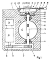
- Fig. 1 ein Schnitt eines Drosselklappenstellers,
- Fig. 2 einen vergrößerten Längsschnitt einer elektromagnetischen Kupplung im Drosselklappensteller in Fig. 1,
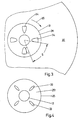
- Fig. 3 und 4 jeweils eine Draufsicht einander gegenüberliegender Kupplungsscheiben der Kupplung in Fig. 2,
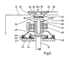
- Fig. 5 eine Seitenansicht von Sollwertgeber und Istwertgeber eines ausschnittweise dargestellten Drosselklappenstellers gemäß einem weiteren Ausführungsbeispiel.
- 1 shows a section of a throttle valve actuator,
- 2 shows an enlarged longitudinal section of an electromagnetic clutch in the throttle valve actuator in FIG. 1,
- 3 and 4 are each a plan view of opposing clutch plates of the clutch in Fig. 2,
- 5 shows a side view of the setpoint generator and actual value generator of a throttle valve actuator shown in detail according to a further exemplary embodiment.
Der in Fig. 1 schematisch im Schnitt dargestellte Drosselklappensteller dient zur Leistungsregelung einer Brennkraftmaschine eines Fahrzeugs, der entsprechend der Stellung des Fahrhebels oder Fahrpedals (nicht dargestellt) eine Drosselklappe 10 im Ansaugkanal 11 der Brennkraftmaschine so verschwenkt, daß sie einen gewissen Öffnungsquerschnitt freigibt und damit die Menge des der Brennkraftmaschine zugeführten Gemisches und letztlich die Leistung der Brennkraftmaschine bestimmt. Die Drosselklappe 10 sitzt drehfest auf einer Drosselklappenwelle 12, die in Lagern 13,14 in einem Gehäuse l5 des Drosselklappenstellers gehalten ist. Auf der Drosselklappenwelle 12 sitzt ein Zahnrad 16, das über einen Zahnriemen 17 von einem Zahnrad 18 angetrieben wird, das auf der Abtriebswelle 19 eines drehrichtungsumkehrbaren elektronisch kommutierten Antriebsmotor, im folgenden Stellmotor 20 genannt, sitzt. Der Stellmotor 20 wird von einer Steuerelektronik 21 gesteuert, welche das elektrische Ausgangssignal eines noch zu beschreibenden Sollwertgebers 22 unter Berücksichtigung weiterer Stellgrößen, wie Schlupf der Antriebsräder, in eine Stellspannung für den Stellmotor 20 umsetzt. Das elektrische Ausgangssignal des Sollwertgebers 22 ist ein direktes Maß für die Stellung des Fahrpedals oder Fahrhebels. Soll durch Niederdrücken des Fahrhebels die Brennkraftmaschine beschleunigt werden, so wird über den Fahrhebel der Sollwertgeber 22 verstellt. Aus dem elektrischen Ausgangssignal des Sollwertgebers 22 erzeugt die Steuerelektronik 21 eine Stellspannung für den Stellmotor 20, und dieser dreht die Drosselklappenwelle 12 um einen bestimmten Drehwinkel. Die Steuerelektronik 21 ist so konzipiert, daß bei Auftreten eines gravierenden Fehlers der Stellmotor 20 abgeschaltet wird und mit die Drosselklappe 10 durch eine nicht dargestellte Rückstellfeder in ihre Schließstellung (Fig. 1) zurückkehrt. Bei fehlender Gemischzufuhr kommt die Brennkraftmaschine zum Stillstand. Um eine gewisse Manövrierfähigkeit des Fahrzeugs sicherzustellen, ist eine Notfahreinrichtung 23 vorgesehen, welche in einem solchen Fall den Fahrhebel direkt mit der Drosselklappenwelle 12 mechanisch verbindet und damit die Verschwenkung des Fahrhebels direkt auf die Drosselklappe 10 überträgt.The throttle valve actuator shown schematically in FIG. 1 is used to control the power of an internal combustion engine of a vehicle which, according to the position of the drive lever or accelerator pedal (not shown), pivots a
Im einzelnen weist die Notfahreinrichtung 23 eine elektromagnetische Kupplung 24 auf, deren erster Kupplungsteil 241 fest mit der Drosselklappenwelle 12 und deren zweiter Kupplungsteil 242 permanent mit dem Fahrhebel verbunden ist. Die Kupplung 24 ist dabei derart ausgebildet, daß die beiden Kupplungsteile 241,242 bei ungestörtem Betrieb der elektrischen Regelung außer Eingriff sind und bei Störung und der damit verbundenen Abschaltung des Stellmotors 20 selbsttätig in Eingriff miteinander gelangen.In detail, the
Wie im einzelnen in Fig. 2 dargestellt ist, wird der erste Kupplungsteil 241 von einem am Ende der Drosselklappenwelle 12 sitzenden Stirnflansch 25 gebildet. Der zweite Kupplungsteil 242, der im Abstand vom Stirnflansch 25 angeordnet ist und konzentrisch die Drosselklappenwelle 12 umgibt, ist im Gehäuse 15 des Drosselklappenstellers schwenkbar gelagert, jedoch gegen axiale Verschiebung im Gehäuse 15 gesichert (vergl. Fig. 1). Der zweite Kupplungsteil 242 enthält den Elektromagneten 26 mit topfförmigem Rückschlußjoch 27, zylinderförmiger Erregerwicklung 28 und die Topföffnung abdeckendem Anker 29. Der Anker 29 ist als Seilscheibe 30 ausgebildet, die drehfest auf einer im Querschnitt T-förmigen Hülse 31 befestigt ist. Die Hülse 31 sitzt frei drehend und axial verschieblich auf der Drosselklappenwelle 12. Im Innern des topfförmigen Rückschlußjoches 27 ist eine als Druckfeder ausgebildete Kupplungsfeder 32 angeordnet, die sich einerseits an der Seilscheibe 30 und andererseits am Rückschlußjoch 27 abstützt und die Hülse 31 über die Seilscheibe 30 gegen die Magnetkraft des Elektromagneten 26 zu verschieben sucht. Bei abgeschaltetem Elektromagneten 26 wird dabei die Hülse 31 mit Seilscheibe 30 auf der Drosselklappenwelle 12 so weit verschoben, daß die einander gegenüberliegenden Stirnflächen 311 der Hülse 31 und 251 des Stirnflansches 25 aneinanderliegen. Sowohl an der Stirnfläche 251 als auch an der Stirnfläche 311 sind axial vorspringende Klauen 33 bzw. 34 angeordnet, die gleichmäßig über den Umfang der Stirnflächen 251 bzw. 311 verteilt angeordnet sind. Wie in Fig. 3 und 4 zu sehen sind, sind auf jeder Stirnfläche 251 bzw. 311 jeweils vier Klauen 33 bzw. 34 vorgesehen, die um jeweils 90° in Umfangsrichtung gegeneinander versetzt sind. Die Abmessungen der Klauen 33,34 in Umfangsrichtung sind relativ klein bemessen, so daß bei in Eingriff miteinander stehenden Klauen 33,34 Stirnflansch 25 und Hülse 31 sich um einen Drehweg s drehen können, ohne daß eine Drehmitnahme des jeweils anderen Teils erfolgt (Fig. 3). Dieses mit s bezeichnete Spiel in der Kupplung 24 dient zur Leistungsreduzierung der Brennkraftmaschine im Notfahrbetrieb.As shown in detail in FIG. 2, the
Wie in Fig. 1 zu sehen ist, greift an der Seilscheibe 30 ein Bowdenzug 36 mit tangentialer Angriffsrichtung an. Dabei ist die Litze 37 des Bowdenzugs 36 an der Seilscheibe 30 befestigt, während sich die Hülle 38 des Bowdenzugs 36 an einem Anschlagwinkel 39 am Gehäuse 15 stirnseitig abstützt. Der Bowdenzug 36 verbindet die Seilscheibe 30 unmittelbar mit dem Fahrhebel, so daß jede Verschwenkung des Fahrhebels in eine entsprechende Verdrehung der Seilscheibe 30 umgesetzt wird. Die in Fig. 2 schematisch dargestellten Anschlußleitungen der Erregerwicklung 28 sind den Anschlüssen des Stellmotors 20 parallel geschaltet.As can be seen in FIG. 1, a Bowden
Der in Fig. 1 schematisch dargestellte Sollwertgeber 22 ist als Drehwinkelpotentiometer ausgebildet, bei welchem ein Schleifer 40 eine ringförmige Schleifbahn 41 kontaktiert und je nach Drehstellung des Schleifers 40 eine entsprechende Ausgangsspannung an der Schleifbahn 41 und/oder am Schleifer 40 abgenommen werden kann. Die Schleifbahn 41 ist als äußere Kreisbahn auf einer Isolierplatte 42 angeordnet, die die Drosselklappenwelle 12 konzentrisch umgibt und im Gehäuse 15 befestigt ist. Der Schleifer 40, hier als Doppelschleifer ausgebildet, ist an dem Rückschlußjoch 27 befestigt und verstellt sich entsprechend dessen Drehbewegung auf der Schleifbahn 41. Mit der Drosselklappe 10 ist noch ein die Drehstellung der Drosselklappe 10 erfassender elektrischer Istwertgeber 43 verbunden, dessen elektrisches Ausgangssignal ein Maß für die Schwenkstellung der Drosselklappe 10 ist und ebenfalls der Steuerelektronik 21 zugeführt wird. Der Istwertgeber 43 ist ebenso wie der Sollwertgeber 22 als Drehwinkelpotentiometer ausgebildet, dessen Schleifbahn 44 konzentrisch zur Schleifbahn 41 auf der Isolierplatte 42 angeordnet ist. Der Schleifer 45 des Istwertgebers 43 ist drehfest mit der Drosselklappenwelle 12 verbunden.The
Die Wirkungsweise des vorstehend beschriebenen Drosselklappenstellers zur Regelung der Leistung einer Brennkraftmaschine ist wie folgt:The operation of the throttle valve actuator described above for regulating the performance of an internal combustion engine is as follows:
In Leerlaufstellung der Brennkraftmaschine, also bei unbetätigtem Fahrhebel, wird von der Steuerelektronik 21 ein bestimmtes Stellsignal an den Stellmotor 20 geliefert, der die Drosselklappe 10 so weit öffnet, daß die Brennkraftmaschine im Leerlauf läuft. Mit der Bestromung des Stellmotors 20 wird auch die Erregerwicklung 28 der elektromagnetischen Kupplung 24 bestromt. Durch die Magnetkraft wird die Seilscheibe 30 gegen die Kraft der Kupplungsfeder 32 axial bis zur Anlage auf der Stirnringfläche des Rückschlußjoches 27 verschoben. Durch die Verschiebung der Seilscheibe 30 kommen die Klauen 33,34 außer Eingriff. Die Kupplung 24 ist ausgerückt, Seilscheibe 30 und Drosselklappenwelle 12 können sich voneinander unbeeinflußt drehen.In the idle position of the internal combustion engine, that is to say when the drive lever is not actuated, the
Soll das Fahrzeug beschleunigt werden, so wird der Fahrer den Fahrhebel niederdrücken. Die Schwenkbewegung des Fahrhebels wird über den Bowdenzug 36 in eine Schwenkbewegung der Seilscheibe 30, und da diese an dem Rückschlußjoch 27 anliegt, in eine Schwenkbewegung des gesamten Kupplungsteils 242 umgesetzt. Durch diese Schwenkbewegung wird der Schleifer 40 des Sollwertgebers 22 auf der Schleifbahn 41 gedreht, wodurch das elektrische Ausgangssignal des Sollwertgebers 22 sich vergrößert. Das der Steuerelektronik 21 zugeführte vergrößerte Ausgangssignal des Sollwertgebers 22 löst die Zufuhr eines entsprechenden Stellsignals an den Stellmotor 20 aus, der über den Zahnriementrieb 16 - 18 die Drosselklappenwelle 12 schwenkt, so daß die von der Drosselklappe 10 freigegebene Durchtrittsöffnung im Ansaugkanal 11 sich vergrößert.If the vehicle is to be accelerated, the driver will depress the driving lever. The pivoting movement of the driving lever is converted via the
Bei Auftreten eines gravierenden Fehlers in der elektrischen Steuerung wird von der Steuerelektronik 21 der Stellmotor 20 stillgesetzt und die Drosselklappe 10 dreht durch die Rückstellfeder in ihre Schließstellung (Fig. 1) zurück. Damit ist die Durchtrittsöffnung im Ansaugkanal 11 völlig geschlossen und die Brennkraftmaschine kommt wegen fehlendem Brennstoffgemisch zum Stillstand. Mit Abschalten des Stellmotors 20 fällt auch die Bestromung der Erregerwicklung 28 des Elektromagneten 26 weg, und die Kupplungsfeder 32 schiebt die Seilscheibe 30 mit Hülse 31 axial nach außen, bis die Klauen 33,34 von Stirnflansch 25 und Hülse 31 axial an den jeweiligen Stirnflächen 311 bzw. 251 anliegen und miteinander in Eingriff kommen. Wird nunmehr der Fahrhebel betätigt, so wird über den Bowdenzug 36 nach wie vor die Seilscheibe 30 in Pfeilrichtung 35 in Fig. 3 geschwenkt. Nach Durchlaufen des Schwenkweges oder des Spiels s kommen die Nocken 34 an der Stirnfläche 11 der Hülse 31 an den Nocken 33 auf der Stirnfläche 251 des Stirnflansches 25 zur Anlage und nehmen diesen in Drehrichtung mit. Damit wird die Drosselklappenwelle 12 gedreht und die Drosselklappe 10 in eine Schwenkstellung überführt, in welcher sie wiederum eine bestimmte Öffnung im Ansaugkanal 11 freigibt. Die Brennkraftmaschine erhält wieder Brennstoffgemisch zugeführt und kann das Fahrzeug in einer Art Notfahrbetrieb antreiben. Durch das Spiel s zwischen den Klauen 33 und 34 ist bei voll niedergedrücktem Fahrhebel die Leistung der Brennkraftmaschine verringert.If a serious error occurs in the electrical control, the
Bei dem in Fig. 5 ausschnittweise dargestellten Drosselklappensteller sind die elektromagnetische Kupplung 24 und der Sollwertgeber 22 in ihrer konstruktiven Ausgestaltung etwas modifiziert, wobei allerdings eine etwas größere axiale Baulänge in Kauf zu nehmen ist. Der zweite Kupplungsteil 242 umschließt nicht mehr die Drosselklappenwelle 12, sondern ist in Verlängerung der Drosselklappenwelle 12 in einem mit 50 schematisch angedeuteten Lager drehbar im Gehäuse 15 gehalten. Von dem zweiten Kupplungsteil 242 ist lediglich die Seilscheibe 30 dargestellt, die drehfest mit einem Stirnflansch 46 verbunden ist, der dem Stirnflansch 25 gegenüberliegt und in gleicher Weise wie die Hülse 31 in Fig. 2 axial vorspringende Klauen 34 trägt, die mit den Klauen 33 am Stirnflansch 25 in Eingriff bringbar sind. Auf die Darstellung des Elektromagneten 26 ist hier verzichtet. Sollwertgeber 22 und Istwertgeber 43 sind wiederum als Drehwinkelpotentiometer ausgebildet und in gleicher Weise angeordnet wie in Fig. 1. Die beiden Schleifbahnen 41 und 44 befinden sich in konzentrischer Anordnung auf der zur Drosselklappenwelle 12 koaxialen Isolierplatte 42 und der Schleifer 45 des Istwertgebers 43 ist wiederum in Ausführung als Doppelschleifer an der Drosselklappenwelle 12 befestigt. Der Schleifer 40 des Sollwertgebers 22 ist als Doppelschleifer an einer Hülse 47 befestigt, die koaxial zur Drosselklappenwelle 12 angeordnet ist, diese umschließt und in einem Lager 48 im Gehäuse 15 drehbar gehalten ist. Die Hülse 47 ist über einen Mitnehmer 49 drehfest mit dem Stirnflansch 46 des zweiten Kupplungsteils 242 verbunden. Die Wirkungsweise des insoweit modifizierten Drosselklappenstellers ist identisch wie vorstehend beschrieben. Da der Drehwinkel der Drehwinkelpotentiometer kleiner als 180° ist, können auch die Schleifbahnen von Sollwertgeber 22 und Istwertgeber 43 als Ringsegmente auf der gleichen Kreisbahn angeordnet werden, die koaxial zur Drosselklappenwelle 12 verläuft. Die Schleifer bleiben nach wie vor an der Drosselklappenwelle 12 bzw. an der Hülse 47 befestigt, sind jedoch als Einfachschleifer ausgebildet.In the throttle valve actuator shown in detail in FIG. 5, the
Zur gemeinsamen Bestromung von Erregerwicklung 28 der Kupplung 24 und des Stellmotors 20 ist erstere entweder in Reihe mit dem Stellmotor 20 geschaltet oder unmittelbar an dessen Anschlußklemmen in Parallelschaltung angeschlossen, so daß eine dem Stellmotor 20 nachgeschaltete elektrische Sicherheitsabschaltung in der Steuerelektronik 21 im Störfall auch die Bestromung der Erregerwicklung 28 beendet.To energize the excitation winding 28 of the clutch 24 and the
Claims (14)
Applications Claiming Priority (2)
| Application Number | Priority Date | Filing Date | Title |
|---|---|---|---|
| DE3811892 | 1988-04-09 | ||
| DE3811892A DE3811892A1 (en) | 1988-04-09 | 1988-04-09 | DEVICE FOR CONTROLLING AN INTERNAL COMBUSTION ENGINE IN VEHICLES |
Publications (2)
| Publication Number | Publication Date |
|---|---|
| EP0337099A2 true EP0337099A2 (en) | 1989-10-18 |
| EP0337099A3 EP0337099A3 (en) | 1989-12-27 |
Family
ID=6351671
Family Applications (1)
| Application Number | Title | Priority Date | Filing Date |
|---|---|---|---|
| EP89103735A Withdrawn EP0337099A3 (en) | 1988-04-09 | 1989-03-03 | Control device for an internal combustion engine in vehicles |
Country Status (4)
| Country | Link |
|---|---|
| US (1) | US5002032A (en) |
| EP (1) | EP0337099A3 (en) |
| JP (1) | JPH01301934A (en) |
| DE (1) | DE3811892A1 (en) |
Cited By (9)
| Publication number | Priority date | Publication date | Assignee | Title |
|---|---|---|---|---|
| EP0402521A1 (en) * | 1989-06-10 | 1990-12-19 | VDO Adolf Schindling AG | Load control apparatus |
| EP0444239A2 (en) * | 1990-02-26 | 1991-09-04 | VDO Adolf Schindling AG | Throttle valve assembly |
| WO1991018194A1 (en) * | 1990-05-18 | 1991-11-28 | Audi Ag | Electrically influenced throttle butterfly adjuster |
| EP0638716A1 (en) * | 1993-08-13 | 1995-02-15 | Pierburg Gmbh | Throttle device for internal combustion engines |
| WO2000008320A1 (en) * | 1998-08-01 | 2000-02-17 | Filterwerk Mann+Hummel Gmbh | Port system, especially an induction manifold for an internal combustion engine |
| EP0982483A2 (en) | 1998-08-25 | 2000-03-01 | Mannesmann VDO Aktiengesellschaft | Driving device |
| EP1126146A2 (en) | 2000-02-18 | 2001-08-22 | Mannesmann VDO Aktiengesellschaft | Throttle body |
| EP1357453A3 (en) * | 2002-04-24 | 2007-06-20 | BorgWarner Inc. | Electric positional actuator |
| WO2008034656A1 (en) * | 2006-09-22 | 2008-03-27 | SIEMENS AKTIENGESELLSCHAFT öSTERREICH | Apparatus for detecting the angle of rotation for a throttle valve operated by means of an electric motor |
Families Citing this family (26)
| Publication number | Priority date | Publication date | Assignee | Title |
|---|---|---|---|---|
| DE4022825A1 (en) * | 1989-08-22 | 1991-02-28 | Bosch Gmbh Robert | DEVICE WITH A THROTTLE ORGAN DETERMINING THE PERFORMANCE OF A DRIVE MACHINE |
| DE3936875A1 (en) * | 1989-11-06 | 1991-05-08 | Hella Kg Hueck & Co | THROTTLE VALVE FOR AN INTERNAL COMBUSTION ENGINE |
| DE3940178A1 (en) * | 1989-12-05 | 1991-06-06 | Teves Gmbh Alfred | Position control system for throttle in vehicle - makes use of two pulley wheels positioned adjacent each other |
| DE4005905A1 (en) * | 1990-02-24 | 1991-08-29 | Bayerische Motoren Werke Ag | Electric motor-driven throttle control for combustion engine - is backed up by emergency traction cable allowing low-speed operation in absence of electric power |
| DE4021691C2 (en) * | 1990-07-07 | 2001-06-28 | Mannesmann Vdo Ag | Potentiometer |
| DE4028702A1 (en) * | 1990-09-10 | 1992-03-12 | Bosch Gmbh Robert | ACTUATOR |
| JPH04224241A (en) * | 1990-12-26 | 1992-08-13 | Aisin Seiki Co Ltd | Throttle control device |
| JPH04231631A (en) * | 1990-12-27 | 1992-08-20 | Aisin Seiki Co Ltd | Throttle control device |
| JP3205002B2 (en) * | 1991-05-20 | 2001-09-04 | 株式会社日立製作所 | Throttle actuator |
| DE4129960C2 (en) * | 1991-09-10 | 2000-11-16 | Hella Kg Hueck & Co | Device for adjusting the driving speed of a motor vehicle |
| JP2921234B2 (en) * | 1992-02-05 | 1999-07-19 | 日産自動車株式会社 | Electronic throttle drive |
| JPH0650201A (en) * | 1992-04-30 | 1994-02-22 | Nippondenso Co Ltd | Driving device for throttle valve |
| JP2758535B2 (en) * | 1992-07-16 | 1998-05-28 | 株式会社日立製作所 | Electronic throttle control |
| JPH07139376A (en) * | 1993-11-19 | 1995-05-30 | Aisin Seiki Co Ltd | Throttle control device |
| JPH10315798A (en) * | 1997-03-17 | 1998-12-02 | Aisin Seiki Co Ltd | Actuator for controlling throttle opening |
| DE19721239A1 (en) * | 1997-05-21 | 1998-12-03 | Hella Kg Hueck & Co | Choke flap actuating arrangement for internal combustion engines |
| JP4509406B2 (en) * | 2000-03-17 | 2010-07-21 | ヤマハ発動機株式会社 | Engine output control device for water jet propulsion boat |
| NL1014911C2 (en) | 2000-04-11 | 2001-10-12 | Skf Eng & Res Centre Bv | Electric screw actuator system. |
| NL1014912C2 (en) * | 2000-04-11 | 2001-10-12 | Skf Eng & Res Centre Bv | Hand control means. |
| DE10319882A1 (en) * | 2003-05-03 | 2004-11-18 | Daimlerchrysler Ag | Power controller with fail-safe device |
| US7086379B2 (en) * | 2004-07-07 | 2006-08-08 | Buell Motorcycle Company | Power control device and method for a motorcycle |
| DE102005042347A1 (en) * | 2005-09-07 | 2007-03-15 | Zf Friedrichshafen Ag | Automatic or automated motor vehicle transmission and method for controlling the same, with an emergency driving operation and a normal driving operation |
| DE102006008051B3 (en) * | 2006-02-21 | 2007-11-29 | Siemens Ag | Adaptive positioning method of an actuator |
| US20090007884A1 (en) * | 2007-07-02 | 2009-01-08 | Bunne Jonathan M | Dual throttle assembly with electronic override |
| CN107152539A (en) * | 2016-03-06 | 2017-09-12 | 张大伟 | Valve control device |
| EP3800716B1 (en) * | 2019-10-03 | 2022-05-04 | Marelli Europe S.p.A. | Throttle valve for adjusting the feeding of a gas to a fuel cell and electric drive vehicle including the throttle valve |
Citations (4)
| Publication number | Priority date | Publication date | Assignee | Title |
|---|---|---|---|---|
| FR2368080A2 (en) * | 1976-10-16 | 1978-05-12 | Bosch Gmbh Robert | VARIABLE STROKE ADJUSTMENT POSITION CONTROL DEVICE |
| GB2068456A (en) * | 1980-01-30 | 1981-08-12 | Lucas Industries Ltd | Internal combustion engine throttle valve control linkage |
| JPS60240835A (en) * | 1984-05-12 | 1985-11-29 | Nissan Motor Co Ltd | Control device of intake air quantity in internal-combustion engine |
| FR2585409A1 (en) * | 1985-07-26 | 1987-01-30 | Marchal Equip Auto | Device for electrically actuating a member, especially a carburettor butterfly flap |
Family Cites Families (8)
| Publication number | Priority date | Publication date | Assignee | Title |
|---|---|---|---|---|
| JPS59122742A (en) * | 1982-12-28 | 1984-07-16 | Mazda Motor Corp | Throttle valve control device in engine |
| JPS59153945A (en) * | 1983-02-21 | 1984-09-01 | Nissan Motor Co Ltd | Apparatus for controlling throttle valve |
| DE3307968A1 (en) * | 1983-03-07 | 1984-09-13 | Vdo Adolf Schindling Ag, 6000 Frankfurt | DEVICE FOR TRANSMITTING THE POSITION OF A SETPOINT VALUE |
| DE3609849C1 (en) * | 1986-03-22 | 1987-07-30 | Daimler Benz Ag | Device for regulating an internal combustion engine in a motor vehicle |
| JPS643239A (en) * | 1987-06-25 | 1989-01-09 | Mitsubishi Motors Corp | Drive by-wire type throttle valve control device with fail-safe mechanism |
| JPH0737770B2 (en) * | 1987-07-24 | 1995-04-26 | 日産自動車株式会社 | Vehicle throttle opening control device |
| DE3730239A1 (en) * | 1987-09-09 | 1989-03-30 | Pierburg Gmbh | ELECTRICALLY CONTROLLABLE ACTUATING DEVICE FOR ADJUSTING THE THROTTLE VALVE OF A COMBUSTION MIXING THROTTLE DEVICE OF INTERNAL COMBUSTION ENGINES |
| JPS6487836A (en) * | 1987-09-30 | 1989-03-31 | Mitsubishi Motors Corp | Safety device for throttle actuator |
-
1988
- 1988-04-09 DE DE3811892A patent/DE3811892A1/en not_active Ceased
-
1989
- 1989-03-03 EP EP89103735A patent/EP0337099A3/en not_active Withdrawn
- 1989-04-07 US US07/334,427 patent/US5002032A/en not_active Expired - Fee Related
- 1989-04-10 JP JP1088204A patent/JPH01301934A/en active Pending
Patent Citations (4)
| Publication number | Priority date | Publication date | Assignee | Title |
|---|---|---|---|---|
| FR2368080A2 (en) * | 1976-10-16 | 1978-05-12 | Bosch Gmbh Robert | VARIABLE STROKE ADJUSTMENT POSITION CONTROL DEVICE |
| GB2068456A (en) * | 1980-01-30 | 1981-08-12 | Lucas Industries Ltd | Internal combustion engine throttle valve control linkage |
| JPS60240835A (en) * | 1984-05-12 | 1985-11-29 | Nissan Motor Co Ltd | Control device of intake air quantity in internal-combustion engine |
| FR2585409A1 (en) * | 1985-07-26 | 1987-01-30 | Marchal Equip Auto | Device for electrically actuating a member, especially a carburettor butterfly flap |
Non-Patent Citations (1)
| Title |
|---|
| PATENT ABSTRACTS OF JAPAN, Band 10, Nr. 109 (M-472)[2166], 23. April 1986; & JP-A-60 240 835 (NISSAN JIDOSHA K.K.) 29-11-1985 * |
Cited By (13)
| Publication number | Priority date | Publication date | Assignee | Title |
|---|---|---|---|---|
| EP0402521A1 (en) * | 1989-06-10 | 1990-12-19 | VDO Adolf Schindling AG | Load control apparatus |
| US5027766A (en) * | 1989-06-10 | 1991-07-02 | Vdo Adolf Schindling Ag | Load adjustment device |
| EP0444239A2 (en) * | 1990-02-26 | 1991-09-04 | VDO Adolf Schindling AG | Throttle valve assembly |
| EP0444239A3 (en) * | 1990-02-26 | 1992-07-08 | Vdo Adolf Schindling Ag | Throttle valve assembly |
| WO1991018194A1 (en) * | 1990-05-18 | 1991-11-28 | Audi Ag | Electrically influenced throttle butterfly adjuster |
| EP0638716A1 (en) * | 1993-08-13 | 1995-02-15 | Pierburg Gmbh | Throttle device for internal combustion engines |
| WO2000008320A1 (en) * | 1998-08-01 | 2000-02-17 | Filterwerk Mann+Hummel Gmbh | Port system, especially an induction manifold for an internal combustion engine |
| EP0982483A2 (en) | 1998-08-25 | 2000-03-01 | Mannesmann VDO Aktiengesellschaft | Driving device |
| EP1126146A2 (en) | 2000-02-18 | 2001-08-22 | Mannesmann VDO Aktiengesellschaft | Throttle body |
| US6646395B2 (en) | 2000-02-18 | 2003-11-11 | Mannesmann Vdo Ag | Throttle body |
| EP1357453A3 (en) * | 2002-04-24 | 2007-06-20 | BorgWarner Inc. | Electric positional actuator |
| WO2008034656A1 (en) * | 2006-09-22 | 2008-03-27 | SIEMENS AKTIENGESELLSCHAFT öSTERREICH | Apparatus for detecting the angle of rotation for a throttle valve operated by means of an electric motor |
| US7798121B2 (en) | 2006-09-22 | 2010-09-21 | Melecs Ews Gmbh & Co Kg | Apparatus for detecting the angle of rotation for a throttle valve operated by means of an electric motor |
Also Published As
| Publication number | Publication date |
|---|---|
| US5002032A (en) | 1991-03-26 |
| DE3811892A1 (en) | 1989-10-19 |
| EP0337099A3 (en) | 1989-12-27 |
| JPH01301934A (en) | 1989-12-06 |
Similar Documents
| Publication | Publication Date | Title |
|---|---|---|
| EP0337099A2 (en) | Control device for an internal combustion engine in vehicles | |
| EP0326553B2 (en) | System for regulated dosing of combustion air into an internal combustion engine | |
| DE3814702A1 (en) | DEVICE FOR ACTUATING THE THROTTLE VALVE OF AN INTERNAL COMBUSTION ENGINE, IN PARTICULAR A MOTOR VEHICLE | |
| DE2724828C2 (en) | Electrically controllable adjusting device | |
| DE3343342C2 (en) | Starter protection device | |
| DE4143079A1 (en) | THROTTLE VALVE CONTROL DEVICE | |
| DE4142809C2 (en) | Throttle valve control device | |
| DE4142810C2 (en) | Throttle valve control device | |
| EP0208222A2 (en) | Idle speed control device for a spark ignition engine, especially for a motor vehicle | |
| DE2637122A1 (en) | CONTROL UNIT FOR INFLUENCING A REGULATED SYSTEM | |
| EP0123731A1 (en) | Device for transmitting the position of a control element | |
| EP0269780A1 (en) | Transmission system for the position of a control element operable by the driver of a vehicle | |
| DE2852211A1 (en) | DEVICE FOR CONTROLLING THE SPEED OF A MOTOR VEHICLE | |
| DE3809910C2 (en) | Device for influencing the performance of internal combustion engines | |
| DE19532590B4 (en) | Motor and hand operated actuator | |
| DE3800876A1 (en) | Power output control device for an internal combustion engine | |
| DE944835C (en) | Control device for an electromagnetic clutch, in particular for the main clutch of motor vehicles | |
| EP0080026A1 (en) | Setting device for a controlled adjustment of a stop connected to an actuator | |
| EP0421047B1 (en) | Load control apparatus | |
| DE2935321C2 (en) | Control device for the injection quantity of a fuel injection pump in a diesel engine | |
| DE102015115654B4 (en) | Encoder for the mixture adjustment of an internal combustion engine | |
| DE19709748A1 (en) | Throttle device for an internal combustion engine | |
| DE1475294C3 (en) | Automatic adjustment device for an electromagnetically operated disc friction clutch or brake | |
| DE19721239A1 (en) | Choke flap actuating arrangement for internal combustion engines | |
| DE3641629A1 (en) | ELEMENTS FOR AUTOMATIC CONTROL AND FUEL SAVING FOR COMBUSTION ENGINES |
Legal Events
| Date | Code | Title | Description |
|---|---|---|---|
| PUAI | Public reference made under article 153(3) epc to a published international application that has entered the european phase |
Free format text: ORIGINAL CODE: 0009012 |
|
| AK | Designated contracting states |
Kind code of ref document: A2 Designated state(s): DE FR GB IT SE |
|
| PUAL | Search report despatched |
Free format text: ORIGINAL CODE: 0009013 |
|
| AK | Designated contracting states |
Kind code of ref document: A3 Designated state(s): DE FR GB IT SE |
|
| 17P | Request for examination filed |
Effective date: 19900515 |
|
| 17Q | First examination report despatched |
Effective date: 19910529 |
|
| RAP3 | Party data changed (applicant data changed or rights of an application transferred) |
Owner name: ROBERT BOSCH GMBH |
|
| STAA | Information on the status of an ep patent application or granted ep patent |
Free format text: STATUS: THE APPLICATION IS DEEMED TO BE WITHDRAWN |
|
| 18D | Application deemed to be withdrawn |
Effective date: 19920527 |