EP0326553B2 - System for regulated dosing of combustion air into an internal combustion engine - Google Patents
System for regulated dosing of combustion air into an internal combustion engine Download PDFInfo
- Publication number
- EP0326553B2 EP0326553B2 EP87905601A EP87905601A EP0326553B2 EP 0326553 B2 EP0326553 B2 EP 0326553B2 EP 87905601 A EP87905601 A EP 87905601A EP 87905601 A EP87905601 A EP 87905601A EP 0326553 B2 EP0326553 B2 EP 0326553B2
- Authority
- EP
- European Patent Office
- Prior art keywords
- actuating shaft
- throttle flap
- return spring
- counterspring
- torque
- Prior art date
- Legal status (The legal status is an assumption and is not a legal conclusion. Google has not performed a legal analysis and makes no representation as to the accuracy of the status listed.)
- Expired - Lifetime
Links
- 238000002485 combustion reaction Methods 0.000 title claims description 23
- 230000001105 regulatory effect Effects 0.000 title 1
- 230000000903 blocking effect Effects 0.000 abstract 1
- 230000008014 freezing Effects 0.000 description 5
- 238000007710 freezing Methods 0.000 description 5
- 238000010586 diagram Methods 0.000 description 2
- 230000006870 function Effects 0.000 description 2
- 230000008878 coupling Effects 0.000 description 1
- 238000010168 coupling process Methods 0.000 description 1
- 238000005859 coupling reaction Methods 0.000 description 1
- 238000011161 development Methods 0.000 description 1
- 230000018109 developmental process Effects 0.000 description 1
- XDDAORKBJWWYJS-UHFFFAOYSA-N glyphosate Chemical compound OC(=O)CNCP(O)(O)=O XDDAORKBJWWYJS-UHFFFAOYSA-N 0.000 description 1
- 239000000203 mixture Substances 0.000 description 1
- 239000007858 starting material Substances 0.000 description 1
- 238000004804 winding Methods 0.000 description 1
Images

Classifications
-
- F—MECHANICAL ENGINEERING; LIGHTING; HEATING; WEAPONS; BLASTING
- F02—COMBUSTION ENGINES; HOT-GAS OR COMBUSTION-PRODUCT ENGINE PLANTS
- F02M—SUPPLYING COMBUSTION ENGINES IN GENERAL WITH COMBUSTIBLE MIXTURES OR CONSTITUENTS THEREOF
- F02M19/00—Details, component parts, or accessories of carburettors, not provided for in, or of interest apart from, the apparatus of groups F02M1/00 - F02M17/00
- F02M19/12—External control gear, e.g. having dash-pots
-
- F—MECHANICAL ENGINEERING; LIGHTING; HEATING; WEAPONS; BLASTING
- F02—COMBUSTION ENGINES; HOT-GAS OR COMBUSTION-PRODUCT ENGINE PLANTS
- F02D—CONTROLLING COMBUSTION ENGINES
- F02D11/00—Arrangements for, or adaptations to, non-automatic engine control initiation means, e.g. operator initiated
- F02D11/06—Arrangements for, or adaptations to, non-automatic engine control initiation means, e.g. operator initiated characterised by non-mechanical control linkages, e.g. fluid control linkages or by control linkages with power drive or assistance
- F02D11/10—Arrangements for, or adaptations to, non-automatic engine control initiation means, e.g. operator initiated characterised by non-mechanical control linkages, e.g. fluid control linkages or by control linkages with power drive or assistance of the electric type
- F02D11/107—Safety-related aspects
Definitions
- the invention is based on a device according to claim 1.
- a desirably low drive power of such a rotary actuator may not be sufficient to "tear" the throttle valve, if it is frozen in its rest position, when the internal combustion engine is started.
- Such a turntable is e.g. known from EP-A-154 036, which is completely closed by the restoring force of a spring in the de-energized state. Furthermore, from JP-A-60 230 520 a variant is known in which the throttle valve is pressed in the closing direction by means of a spring against a fixedly adjustable stop.
- electronic systems for adjusting the throttle valve on an internal combustion engine provide almost any translation between the accelerator pedal position and the throttle valve position, for example using a characteristic curve or a map stored in a digital memory.
- a first advantage of the invention is that the problem of freezing of the throttle valve is overcome by the freezing of the throttle valve no longer being able to occur when the vehicle is parked because the throttle valve does not assume a rest position in this state in such a way that it could freeze flat. In this way, the provision of appropriate peak drive power to tear away a flat frozen throttle valve is completely eliminated, which leads to a cost-effective design of the required control output stage in an electronic control unit.
- Another advantage of the invention is that in the event of failure of the electronic control unit, or its power supply, or the control output stage for the throttle valve contained in this control unit, the latter assumes such a rest position due to recirculation by a spring that sufficient combustion air is still available to maintain emergency operation in the internal combustion engine can get.
- Another advantage of the invention is that when the vehicle electrical system voltage drops during start-up attempts at a low ambient temperature, no additional electrical energy has to be provided, only to allow sufficient combustion air to get into the internal combustion engine. This improves the voltage level of the vehicle electrical system, particularly when the starter battery is under high stress.
- FIG. 1 shows a schematic functional diagram of the device according to the invention for the electrically controlled metering of combustion air into an internal combustion engine
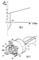
- FIG. 2 shows a diagram of the basic course of the torque of a throttle valve rotary actuator over the position angle ⁇ of the throttle valve
- FIG. 3 shows a schematic illustration of a practical implementation of the device according to the invention .
- the device according to the invention for the electrically controlled metering of combustion air into an internal combustion engine comprises a channel 10 for guiding combustion air 28, through which a rotatably mounted actuating shaft 12 projects, which in turn carries a throttle valve 11 which is fastened to it and thereby pivotable.
- the adjusting shaft 12 is driven or positioned by an electromotive actuator 13; the necessary control signals are fed to the turntable via connecting lines 14.
- the adjusting shaft 12 carries a driver 18, which serves as a movable abutment for a first end 17 of a return spring 15.
- the second end 16 of this return spring 15 is suitably fixed in space.
- the return spring 15 generates a certain restoring torque, which the throttle valve 11 seeks to return to the closed position.
- the lines 26a and 26b represent that surface line of the combustion air duct 10 against which the throttle valve 11 rests in the completely closed state, ie along which the throttle valve could freeze "flat" along its entire circumference.
- the setting shaft 12 also carries a further driver 19.
- a second counter-spring 21 is clamped in a spatially fixed manner at one end 22; the second end 23 rests on an abutment 25 which is adjustable tangentially to the actuating shaft 12, so that the spring is under a certain rest tension.
- the throttle valve 11 does not close completely and that the electromotive actuator 13 has to generate a changing torque in order to adjust the throttle valve from the maximum opening into the fully closed position, so that its edges on the aforementioned surface lines 26a and 26b.
- the throttle valve 11 In the torque-free state, that is to say when the actuator 13 is de-energized, the throttle valve 11 thus has a certain rest opening angle ⁇ r , which can be precisely adjusted by adjusting the adjustable stop element 25.
- FIG. 2 illustrates the course of the normalized torque Mc to be applied by the electromotive actuator 13 over the position angle a of the throttle valve 11; at the rest angle ⁇ r of the throttle valve, the directional reversal of the actuating torque occurs, so that the electromotive actuator 13, in order to bring the throttle valve 11 into the completely closed position, must generate an actuating torque with the opposite sign.
- the slope of the torque line in the range 0 ⁇ ⁇ r is obtained by superimposing the characteristic torque curve for the spring 15 and for the counter spring 21.
- the scope of the invention is not left by a different design of the springs 15 and 21, for example in the form of spiral springs or curved strip springs; the elements described can also be arranged either distributed on one side or on both sides of the throttle valve.
- the driver 18 can also be designed as an abutment for the return spring 15 and the driver 19 with the abutment 20 for the counter spring 21 as a single body, in that both springs act on a single, rotationally fixedly connected to the actuating shaft 12 driver element, as this is illustrated in Figure 3 for completeness.
Landscapes
- Engineering & Computer Science (AREA)
- Chemical & Material Sciences (AREA)
- Combustion & Propulsion (AREA)
- Mechanical Engineering (AREA)
- General Engineering & Computer Science (AREA)
- Control Of Throttle Valves Provided In The Intake System Or In The Exhaust System (AREA)
Abstract
Description
Die Erfindung geht aus von einer Einrichtung nach des dem ersten Teil Anspruchs 1.The invention is based on a device according to
Aus der deutschen Patentschrift 10 23 268 ist eine Vorrichtung zum Verstellen der Drosselklappe einer Brennkraftmaschine in einem Kraftfahrzeug bekannt. Diese Vorrichtung umfaßt ein Schlitzhebelgetriebe, mit dessen Hilfe zum einen die Geradführung eines Gaspedalgestänges durch eine besser schmierbare Schwingenführung ersetzt wird. Zum anderen wird dort mit Hilfe einer zwischen zwei festen Anschlägen vorgespannten Feder und eines Schwinghebelanschlags eine verstärkte Rückstellkraft erzeugt, sobald der Betätigungshebel in eine Stellung zwischen einer bestimmten Grenzlage I und der Maximalstellung II gebracht wird. Es wird also ein Druckpunkt vorgesehen, der dem Fahrzeugführer das Erreichen einer bestimmten Öffnung der Drosselklappe anzeigt (Kick-Down-Schwelle). Durch geeignete Gestaltung der Kontur des Getriebsschlitzes im Schlitzhebel läßt jene Vorrichtung im übrigen auf rein mechanische Weise eine nicht winkeltreue, sondern beispielsweise fahrzeug- oder motorspezifisch angepaßte Übersetzung der Fahrpedalstellung auf die Drosselklappenstellung zu, so daß auch eine nicht proportionale Abhängigkeit der Drosselklappenstellung von der Fahrpedalstellung leicht zu realisieren ist. Diese bekannte Lösung sieht jedoch keinerlei Maßnahmen sowohl zur Bereitstellung einer Notfahrfunktion noch zum Vermeiden des Festfrierens der Drosselklappe vor.From the German patent 10 23 268 a device for adjusting the throttle valve of an internal combustion engine in a motor vehicle is known. This device comprises a slotted lever gear, with the help of which the straight guidance of an accelerator pedal linkage is replaced by a more lubricatable rocker guide. On the other hand, with the help of a spring preloaded between two fixed stops and a rocking lever stop, an increased restoring force is generated as soon as the actuating lever is brought into a position between a certain limit position I and the maximum position II. A pressure point is therefore provided which indicates to the vehicle driver that a certain opening of the throttle valve has been reached (kick-down threshold). By suitably designing the contour of the gear slot in the slotted lever, that device allows in a purely mechanical way a translation of the accelerator pedal position to the throttle valve position that is not adapted to the angle, but rather, for example, adapted to the vehicle or engine, so that a non-proportional dependence of the throttle valve position on the accelerator pedal position is also easy is to be realized. However, this known solution does not provide any measures either to provide an emergency drive function or to prevent the throttle valve from freezing up.
Bei neueren, elektronisch arbeitenden Systemen zur Gemischzumessung entfällt in der Regel eine mechanische Kopplung zwischen Fahrpedal und Drosselklappe. Vielmehr wird bei solchen Sysemen die Drosselklappe von einem elektromotorischen Steller angetrieben oder eingestellt, welcher Stellbefehle unmittelbar von einem elektronischen Steuergerät über eine elektrische Leitung empfängt; dasselbe elektronische Steuergerät empfängt hierzu von einem Fahrpedalstellungsgeber den Fahrerwunsch ebenfalls über eine elektrische Leitung. Als elektromotorische Steller kommen dabei untersetzte Gleichstrommotoren (meist in permanenterregter Ausführung) oder sogenannte Drehsteller in Betracht, die im Prinzip ähnlich wie ein Drehspulmeßwerk funktionieren und jedenfalls in Abhängigkeit von der mittleren Stromstärke bzw. des Tastverhältnisses des Betriebsstromes in wenigstens einer Stellwicklung eine bestimmte Lage einnehmen. Um solche Drehsteller mit einer geringstmöglichen elektrischen Leistung betreiben zu können, kann die Federkonstante der Rückstellfeder der Drosselklappe nicht beliebig groß gemacht werden. Andererseits reicht eine wünschenswert geringe Antriebsleistung eines solchen Drehstellers unter Umständen nicht aus, um die Drosselklappe, falls sie in ihrer Ruhelage festgefroren ist, bei Inbetriebnahme der Brennkraftmaschine "Ioszureißen".In newer, electronically operating systems for metering the mixture, there is usually no mechanical coupling between the accelerator pedal and the throttle valve. Rather, in such systems the throttle valve is driven or set by an electromotive actuator which receives control commands directly from an electronic control unit via an electrical line; the same electronic control unit also receives the driver's request from an accelerator pedal position transmitter via an electrical line. Reduced-current DC motors (usually in a permanently excited version) or so-called rotary actuators come into consideration as electromotive actuators, which in principle function similarly to a moving coil measuring mechanism and in any case assume a certain position in at least one actuating winding depending on the average current strength or the duty cycle of the operating current. In order to be able to operate such rotary actuators with the lowest possible electrical power, the spring constant of the return spring of the throttle valve cannot be made arbitrarily large. On the other hand, a desirably low drive power of such a rotary actuator may not be sufficient to "tear" the throttle valve, if it is frozen in its rest position, when the internal combustion engine is started.
Ein solcher Drehsteller ist z.B. aus der EP-A-154 036 bekannt, der durch die rückstellende Kraft einer Feder im stromlosen Zustand vollständig geschlossen wird. Weiterhin ist aus der JP-A-60 230 520 eine Variante bekannt, bei der die Drosselklappe in Schließrichtung mittels einer Feder gegen einen fest justierbaren Anschlag gedrückt wird.Such a turntable is e.g. known from EP-A-154 036, which is completely closed by the restoring force of a spring in the de-energized state. Furthermore, from JP-A-60 230 520 a variant is known in which the throttle valve is pressed in the closing direction by means of a spring against a fixedly adjustable stop.
Demgegenüber leisten elektronische Systeme zur Einstellung der Drosselklappe an einer Brennkraftmaschine die Realisierung nahezu beliebiger Übersetzungen zwischen der Fahrpedalstellung und der Drosselklappenstellung, beispielsweise unter Benutzung einer in einem Digitalspeicher abgelegten Kennlinie oder eines Kennfeldes.In contrast, electronic systems for adjusting the throttle valve on an internal combustion engine provide almost any translation between the accelerator pedal position and the throttle valve position, for example using a characteristic curve or a map stored in a digital memory.
Es ist daher Aufgabe der Erfindung in Verbindung mit zeitgemäßen elektronischen Zumeßsystemen eine einfache Einrichtung zu schaffen, welche einen zuverlässigen Antrieb einer luftzumessenden Drosselklappe einer Brennkraftmaschine mit geringer Antriebsleistung erlaubt, und die zudem das Problem einer festfrierenden Drosselklappe ausräumt. Weiter ist es Aufgabe der Erfindung, diese Einrichtung so zu gestalten, daß im Falle eines Ausfalles der Stromversorgung, des elektronischen Steuergerätes für die Drosselklappenstellung oder des die Drosselklappe einstellenden Stellers dennoch ein sicherer Notfahrbetrieb möglich ist, so daß jedenfalls der Fahrzeugführer das Fahrzeug noch zur nächsten Werkstatt fahren kann.It is therefore an object of the invention in connection with contemporary electronic metering systems to provide a simple device which allows a reliable drive of an air-measuring throttle valve of an internal combustion engine with low drive power, and which also eliminates the problem of a freezing throttle valve. Furthermore, it is an object of the invention to design this device so that in the event of a failure of the power supply, the electronic control unit for the throttle valve position or the actuator adjusting the throttle valve, safe emergency operation is nevertheless possible, so that the driver of the vehicle can drive the vehicle to the next Workshop can drive.
Dies wird erreicht mit einer Einrichtung gemäß Anspruch 1.This is achieved with a device according to
Ein erster Vorteil der Erfindung besteht darin, daß das Problem des Festfrierens der Drosselklappe überwunden wird, indem das Festfrieren der Drosselklappe bei abgestelltem Fahrzeug gar nicht mehr eintreten kann, weil die Drosselklappe in diesem Zustand keine Ruhelage derart einnimmt, daß sie flächig festfrieren könnte. Auf diese Weise entfällt die Bereitstellung entsprechender Spitzenantriebsleistung zum Losreißen einer flächig festgefrorenen Drosselklappe völlig, was zu einer kostengünstigen Auslegung der erforderlichen Ansteuerendstufe in einem elektronischen Steuergerät führt. Ein weiterer Vorteil der Erfindung besteht darin, daß bei Ausfall des elektronischen Steuergerätes, oder seiner Stromversorgung, oder der in diesem Steuergerät enthaltenen Ansteuerendstufe für die Drosselklappe diese aufgrund Rückführung durch eine Feder jedenfalls eine solche Ruhelage einnimmt, daß noch ausreichend Verbrennungsluft zur Aufrechterhaltung eines Notfahrbetriebs in die Brennkraftmaschine gelangen kann. Ein weiterer Vorteil der Erfindung besteht darin, daß bei Absinken der Bordnetzspannung bei Startversuchen bei niedriger Umgebungstemperatur keine zusätzliche elektrische Energie bereitgestellt werden muß, nur um ausreichend Verbrennungsluft in die Brennkraftkraftmaschine gelangen zu lassen. Dadurch wird die Spannungslage des Bordnetzes insbesondere bei hoher Beanspruchung der Starterbatterie verbessert.A first advantage of the invention is that the problem of freezing of the throttle valve is overcome by the freezing of the throttle valve no longer being able to occur when the vehicle is parked because the throttle valve does not assume a rest position in this state in such a way that it could freeze flat. In this way, the provision of appropriate peak drive power to tear away a flat frozen throttle valve is completely eliminated, which leads to a cost-effective design of the required control output stage in an electronic control unit. Another advantage of the invention is that in the event of failure of the electronic control unit, or its power supply, or the control output stage for the throttle valve contained in this control unit, the latter assumes such a rest position due to recirculation by a spring that sufficient combustion air is still available to maintain emergency operation in the internal combustion engine can get. Another advantage of the invention is that when the vehicle electrical system voltage drops during start-up attempts at a low ambient temperature, no additional electrical energy has to be provided, only to allow sufficient combustion air to get into the internal combustion engine. This improves the voltage level of the vehicle electrical system, particularly when the starter battery is under high stress.
Durch die in den Unteransprüchen aufgeführten Maßnahmen sind vorteilhafte Weiterbildungen der erfindungsgemäßen Einrichtung zur elektrisch gesteuerten Zumessung von Verbrennungsluft in einer Brennkraftmaschine gegeben.By those listed in the subclaims Measures are advantageous developments of the device according to the invention for the electrically controlled metering of combustion air in an internal combustion engine.
Ein Ausführungsbeipiel der Erfindung ist in der Zeichnung dargestellt und in der nachfolgenden Beschreibung näher erläutert. Es zeigen: Figur 1 ein schematisches Funktionsbild der erfindungsgemäßen Einrichtung zur elektrisch gesteuerten Zumessung von Verbrennungsluft in eine Brennkraftmaschine, Figur 2 ein Daigramm des prinzipiellen Verlaufs des Drehmoments eines Drosselklappendrehstellers über dem Stellungswinkel a der Drosselklappe und Figur 3 eine schematische Darstellung einer praktischen Realiserung der erfindungsgemäßen Einrichtung.An exemplary embodiment of the invention is shown in the drawing and explained in more detail in the following description. FIG. 1 shows a schematic functional diagram of the device according to the invention for the electrically controlled metering of combustion air into an internal combustion engine, FIG. 2 shows a diagram of the basic course of the torque of a throttle valve rotary actuator over the position angle α of the throttle valve, and FIG. 3 shows a schematic illustration of a practical implementation of the device according to the invention .
Gemäß Figur 1 umfaßt die erfindungsgemäße Einrichtung zur elektrisch gesteuerten Zumessung von Verbrennungsluft in eine Brennkraftmaschine einen Kanal 10 zur Führung von Verbrennungsluft 28, durch den eine drehbar gelagerte Stellwelle 12 ragt, die ihrerseits eine daran befestigte und dadurch schwenkbare Drosselklappe 11 trägt. Die Stellwelle 12 wird von einem elektromotorischen Steller 13 angetrieben bzw. positioniert; die dazu notwendigen Stellsignale werden dem Drehsteller über Anschlußleitungen 14 zugeführt. Die Stellwelle 12 trägt einen Mitnehmer 18, der als bewegliches Widerlager für ein erstes Ende 17 einer Rückführfeder 15 dient. Das zweite Ende 16 dieser Rückführfeder 15 ist in geeigneter Weise raumfestbefestigt. Die Rückführfeder 15 erzeugt ein gewisses Rückstelldrehmoment, welches die Drosselklappe 11 in die geschlossene Stellung zurückzuführen sucht. Die Linien 26a und 26b repräsentieren diejenige Mantellinie des Verbrennungsluftkanals 10, an denen die Drosselklappe 11 in völlig geschlossenem Zustand anliegt, d.h. entlang denen die Drosselklappe längs ihres gesamten Umfanges "flächig" festfrieren könnte. Die Stellwelle 12 trägt ferner einen weiteren Mitnehmer 19. Eine zweite Gegenstellfeder 21 ist mit ihrem einen Ende 22 raumfest eingespannt; das zweite Ende 23 liegt an einem tangential zur Stellwelle 12 justierbaren Widerlager 25 an, so daß die Feder unter einer gewissen Ruhespannung steht. Der mit der Stellwelle 12 drehfest verbundene Mitnehmer 19 weist ein Wiederlager 20 auf, das durch die Rückstellfeder 15 und durch das über den Mitnehmer 18 auf die Stellwelle 12 übertragene Rückstelldrehmoment gegen das ruhende Ende 23 der Gegenfeder 21 als Ruhelager geführt wird. Auf diese Weise wird erreicht, daß die Drosselklappe 11 nicht vollständig schließt und daß der elektromotorische Steller 13 ein im Vorzeichen wechselndes Drehmoment erzeugen muß, um die Drosselklappe von der maximalen Öffnung in die völlig geschlossene Lage zu verstellen, so daß deren Berandung an der erwähnten Mantellinien 26a und 26b anliegt. Im drehmomentlosen Zustand, also bei stromlosem Steller 13, weist die Drosselklappe 11 also einen gewissen Ruheöffnungswinkel αr auf, der durch Justierung des verstellbaren Anschlagselements 25 genau einstellbar ist. Es ist ersichtlich, daß somit bei abgestelltem Fahrzeug die Drosselklappe 11 nicht entlang ihres Umfanges im Bereich der Umfangslinien 26a und 26b im völlig geschlossenen Zustand anfrieren kann; eine Verbindung besteht in diesem Falle mit dem Verbrennungsluftkanal 10 nur über die hier nicht gezeigte Lagerung der Stellwelle 12, die jedoch auf einfache Weise gegen Festfrieren gesichert werden kann.According to FIG. 1, the device according to the invention for the electrically controlled metering of combustion air into an internal combustion engine comprises a channel 10 for guiding
Figur 2 veranschaulicht den Verlauf des vom elektromotorischen Steller 13 aufzubringenden normierten Drehmomentes Mc über dem Stellungswinkel a der Drosselklappe 11; beim Ruhewinkel αr der Drosselklappe erfolgt die erwähnte Richtungsumkehr des Stelldrehmomentes, so daß also der elektromotorische Steller 13, um die Drosselklappe 11 in die völlig geschlossene Lage zu bringen, ein Stelldrehmoment mit umgekehrtem Vorzeichen erzeugen muß. Die Steigung der Momentenlinie im Bereich 0<α<αr ergibt sich durch Überlagerung der Momentenkennlinie für die Feder 15 und für die Gegenfeder 21.FIG. 2 illustrates the course of the normalized torque Mc to be applied by the
Der Rahmen der Erfindung wird durch andersartige Ausgestaltung der Federn 15 und 21, beispielsweise in Form von Spiralfedern oder gekrümmten Streifenfedern, nicht verlassen; auch können die beschriebenen Elemente beliebigerweise entweder einseitig oder beidseitig verteilt der Drosselklappe angeordnet sein. Insbesondere können auch der Mitnehmer 18 als Widerlager für die Rückstellfeder 15 und der Mitnehmer 19 mit dem Widerlager 20 für die Gegenfeder 21 als ein einkörperliches Ganzes ausgeführt sein, indem dann beide Federn auf ein einziges, drehfest mit der Stellwelle 12 verbundenes Mitnehmerelement einwirken, wie dies in Figur 3 der Vollständigkeit halber veranschaulicht ist.The scope of the invention is not left by a different design of the
Claims (7)
- Device for the controlled proportioning of combustion air into an internal-combustion engine, with a combustion-air channel (10), with a throttle flap (11) arranged in the combustion-air channel (10) and fastened to a rotatable actuating shaft (12), with a first return spring (15) which is fastened fixedly in space at one end and which, in continuous engagement with the actuating shaft, introduces into the actuating shaft a torque directed with the effect of a closing of the throttle flap, and with an electromotive torque generator connected fixedly in terms of rotation to the actuating shaft and in the form of an actuator, the throttle flap (11) being guidable into a position of rest against a stop by the return spring (15), characterized in that the stop is sprung by means of a counterspring (21) which is under a particular tension at rest and which assumes such a position of rest that sufficient combustion air for maintaining an emergency running mode can still enter the internal-combustion engine, and in that for the complete closing of the throttle flap the electromotive actuator can be controlled in such a way that it generates a torque which is opposed to the torque for the maximum opening of the throttle flap.
- Device according to Claim 1, characterized in that the spring constant of the counterspring (21) is greater than that of the return spring (15).
- Device according to one of the preceding claims, characterized in that the counterspring (21) is fastened fixedly in space at one end, and in that, with the throttle flap opened, the other end of the counter spring can be prestressed by means of an abutment adjustable in the circumferential direction of the actuating shaft.
- Device according to Claim 3, characterized in that the adjustable abutment (25) is designed so that, as a result of its adjustment, it makes it possible to fix the smallest opening angle (αr) of the throttle flap (11) when the actuator (13) is currentless.
- Device according to one of the preceding claims, characterized in that the return spring (15) and the counterspring (21) are arranged so as to engage on the actuating shaft (12) on different sides of the throttle flap (11).
- Device according to one of the preceding claims, characterized in that the return torque is introduced from the return spring (15) into the actuating shaft (12) by means of a driver (18 and 19) which is essentially identical to the driver butting against the counterspring (21).
- Device according to one of the preceding claims, characterized in that both the return spring (15) and the counterspring (21) are arranged so as to engage on the actuating shaft (12) on the same side of the throttle flap.
Applications Claiming Priority (3)
| Application Number | Priority Date | Filing Date | Title |
|---|---|---|---|
| DE3631283 | 1986-09-13 | ||
| DE3631283A DE3631283C2 (en) | 1986-09-13 | 1986-09-13 | Device for the controlled metering of combustion air in an internal combustion engine |
| PCT/DE1987/000404 WO1988002064A1 (en) | 1986-09-13 | 1987-09-04 | System for regulated dosing of combustion air into an internal combustion engine |
Publications (3)
| Publication Number | Publication Date |
|---|---|
| EP0326553A1 EP0326553A1 (en) | 1989-08-09 |
| EP0326553B1 EP0326553B1 (en) | 1990-12-27 |
| EP0326553B2 true EP0326553B2 (en) | 1995-11-08 |
Family
ID=6309579
Family Applications (1)
| Application Number | Title | Priority Date | Filing Date |
|---|---|---|---|
| EP87905601A Expired - Lifetime EP0326553B2 (en) | 1986-09-13 | 1987-09-04 | System for regulated dosing of combustion air into an internal combustion engine |
Country Status (5)
| Country | Link |
|---|---|
| US (1) | US4947815A (en) |
| EP (1) | EP0326553B2 (en) |
| JP (1) | JP2865667B2 (en) |
| DE (2) | DE3631283C2 (en) |
| WO (1) | WO1988002064A1 (en) |
Families Citing this family (75)
| Publication number | Priority date | Publication date | Assignee | Title |
|---|---|---|---|---|
| EP0420303B1 (en) * | 1987-09-22 | 1995-05-17 | Mitsubishi Denki Kabushiki Kaisha | Throttle valve actuator including separate valve driving devices |
| FR2639679B1 (en) * | 1988-11-25 | 1994-02-11 | Solex | THREAD BODY CONTROL DEVICE FOR FUEL SUPPLY SYSTEM OF INTERNAL COMBUSTION ENGINE |
| DE3900437C1 (en) * | 1989-01-10 | 1989-11-16 | Vdo Adolf Schindling Ag, 6000 Frankfurt, De | |
| DE3908596C2 (en) * | 1989-03-16 | 1999-11-11 | Bosch Gmbh Robert | Device for transmitting a set position of a setpoint device |
| DE3918852A1 (en) * | 1989-06-09 | 1990-12-13 | Pierburg Gmbh | ELECTRICALLY CONTROLLED THROTTLE OPERATING DEVICE FOR INTERNAL COMBUSTION ENGINES |
| DE3918853A1 (en) * | 1989-06-09 | 1990-12-13 | Pierburg Gmbh | ELECTRICALLY CONTROLLED THROTTLE OPERATING DEVICE FOR INTERNAL COMBUSTION ENGINES |
| DE4015293A1 (en) * | 1989-12-12 | 1991-06-13 | Bosch Gmbh Robert | SYSTEM FOR CONTROLLING AN OPERATING PARAMETER OF AN INTERNAL COMBUSTION ENGINE OF A MOTOR VEHICLE |
| US5163400A (en) * | 1990-01-16 | 1992-11-17 | Sawafuji Electric Co. Ltd. | Engine unit |
| US5146887A (en) * | 1990-07-12 | 1992-09-15 | General Motors Corporation | Valve assembly |
| DE4027269A1 (en) * | 1990-08-29 | 1992-03-05 | Vdo Schindling | THROTTLE VALVE CONNECTOR |
| DE4027578A1 (en) * | 1990-08-31 | 1992-03-05 | Bosch Gmbh Robert | LOAD ADJUSTMENT DEVICE, IN PARTICULAR FOR A VEHICLE |
| DE4029537A1 (en) * | 1990-09-18 | 1992-03-19 | Bosch Gmbh Robert | METHOD AND DEVICE FOR CONTROLLING AND / OR REGULATING AN OPERATING SIZE OF AN INTERNAL COMBUSTION ENGINE |
| DE9013980U1 (en) * | 1990-10-08 | 1992-02-06 | Hella KG Hueck & Co., 59557 Lippstadt | Throttle body for an internal combustion engine, in particular for motor vehicles |
| DE4037502A1 (en) * | 1990-11-26 | 1992-05-27 | Hella Kg Hueck & Co | DEVICE FOR CONTROLLING THE POWER OUTPUT OF AN INTERNAL COMBUSTION ENGINE, IN PARTICULAR FOR MOTOR VEHICLES |
| IT1241015B (en) * | 1990-12-07 | 1993-12-27 | Weber Srl | SYSTEM FOR THE ADJUSTMENT OF THE AIR FLOW ALONG A THROTTLE BODY OF A SUPPLY DEVICE OF AN ENDOTHERMIC MOTOR OF A VEHICLE. |
| DE4214179C1 (en) * | 1992-04-30 | 1993-05-06 | Mercedes-Benz Aktiengesellschaft, 7000 Stuttgart, De | |
| US5311849A (en) * | 1992-07-14 | 1994-05-17 | Gas Research Institute | Carburetor assembly for an internal combustion gas engine |
| US5423344A (en) * | 1994-01-28 | 1995-06-13 | Miller; Robert S. | Gas blanketed liquid storage system, gas pressure regulation device, counterspring regulator and process for gas blanketing a liquid storage vessel |
| US5429090A (en) | 1994-02-28 | 1995-07-04 | Coltec Industries Inc. | Fail safe throttle positioning system |
| WO1995035440A2 (en) * | 1994-06-18 | 1995-12-28 | Ab Elektronik Gmbh | Throttle valve device |
| DE19604133B4 (en) * | 1996-02-06 | 2008-12-24 | Robert Bosch Gmbh | Method and device for controlling a power control element of a drive unit |
| DE19610210B4 (en) * | 1996-03-15 | 2011-12-08 | Robert Bosch Gmbh | Method for position control of an actuating element of an internal combustion engine |
| DE19612869A1 (en) * | 1996-03-30 | 1997-10-02 | Bosch Gmbh Robert | Control device for controlling a power of an engine |
| JPH102236A (en) * | 1996-06-17 | 1998-01-06 | Aisan Ind Co Ltd | Controller for throttle valve |
| EP1512857A3 (en) * | 1996-09-03 | 2011-04-20 | Hitachi Automotive Systems, Ltd. | A throttle valve control device for an internal combustion engine |
| JPH1076841A (en) * | 1996-09-06 | 1998-03-24 | Calsonic Corp | Heat pump type air conditioner for automobile |
| JP3161978B2 (en) * | 1996-09-12 | 2001-04-25 | 株式会社日立製作所 | Engine throttle device |
| DE19740204B4 (en) * | 1996-09-12 | 2005-07-14 | Hitachi, Ltd. | Throttle device for internal combustion engines |
| JPH10100662A (en) * | 1996-09-25 | 1998-04-21 | Calsonic Corp | Air conditioner for automobile |
| EP0842799A3 (en) | 1996-11-15 | 2003-03-05 | Calsonic Kansei Corporation | Heat pump type air conditioning system for automotive vehicle |
| DE69734308T2 (en) | 1996-11-15 | 2006-06-14 | Calsonic Kansei Corp | Vehicle air conditioning |
| JP3331135B2 (en) * | 1997-01-09 | 2002-10-07 | 株式会社ユニシアジェックス | Intake throttle valve device for internal combustion engine |
| JP3397613B2 (en) * | 1997-01-09 | 2003-04-21 | 株式会社日立ユニシアオートモティブ | Position return or holding device for reciprocating mechanism |
| JP3404254B2 (en) | 1997-05-07 | 2003-05-06 | 株式会社日立製作所 | Engine throttle device |
| JP3847905B2 (en) * | 1997-06-30 | 2006-11-22 | カルソニックカンセイ株式会社 | Heat pump type automotive air conditioner |
| DE19740347B4 (en) * | 1997-09-13 | 2009-06-04 | Daimler Ag | Method and device for controlling the throttle valve of an internal combustion engine |
| US6105666A (en) * | 1997-10-30 | 2000-08-22 | Calsonic Corporation | Vehicular air conditioning apparatus |
| US6039027A (en) * | 1997-12-04 | 2000-03-21 | Unisia Jecs Corporation | Throttle valve device |
| DE19801187B4 (en) * | 1998-01-15 | 2007-07-12 | Robert Bosch Gmbh | Method and device for operating an internal combustion engine |
| DE19840677A1 (en) | 1998-09-07 | 2000-03-09 | Bosch Gmbh Robert | Control device for controlling the power of a drive machine, esp. for motor vehicle, displaces drive element so that drive stops disengage if drive resistance threshold is exceeded |
| JP3511577B2 (en) | 1998-10-06 | 2004-03-29 | 株式会社日立製作所 | Throttle device for internal combustion engine |
| US6095488A (en) * | 1999-01-29 | 2000-08-01 | Ford Global Technologies, Inc. | Electronic throttle control with adjustable default mechanism |
| US6244565B1 (en) | 1999-01-29 | 2001-06-12 | Ford Global Technologies, Inc. | Throttle body shaft axial play control |
| US6155533C1 (en) * | 1999-01-29 | 2002-07-30 | Visteon Global Tech Inc | Default mechanism for electronic throttle control system |
| US6070852A (en) * | 1999-01-29 | 2000-06-06 | Ford Motor Company | Electronic throttle control system |
| US6299545B1 (en) | 1999-05-03 | 2001-10-09 | Visteon Global Tech., Inc. | Rotating shaft assembly |
| JP3992928B2 (en) | 1999-05-10 | 2007-10-17 | 株式会社日立製作所 | Throttle device for internal combustion engine |
| US6488010B2 (en) | 2000-01-18 | 2002-12-03 | Hitachi, Ltd. | Throttle device for internal-combustion engine |
| KR20010103146A (en) * | 1999-05-10 | 2001-11-23 | 가나이 쓰토무 | Throttle device for internal-combustion engine |
| DE19928632A1 (en) * | 1999-06-23 | 2000-12-28 | Mannesmann Vdo Ag | Load adjustment device |
| DE10031835A1 (en) | 1999-06-30 | 2001-01-11 | Hitachi Ltd | Electric choke controller has drive motor with even and odd numbers of lamella appearing alternately in equivalent electrical circuit for wiring between lamella, including brushes |
| JP2001082181A (en) * | 1999-09-20 | 2001-03-27 | Mikuni Corp | Throttle valve control device |
| US6173939B1 (en) | 1999-11-10 | 2001-01-16 | Ford Global Technologies, Inc. | Electronic throttle control system with two-spring failsafe mechanism |
| US6253732B1 (en) | 1999-11-11 | 2001-07-03 | Ford Global Technologies, Inc. | Electronic throttle return mechanism with a two-spring and two-lever default mechanism |
| US6267352B1 (en) | 1999-11-11 | 2001-07-31 | Ford Global Technologies, Inc. | Electronic throttle return mechanism with default and gear backlash control |
| US6286481B1 (en) | 1999-11-11 | 2001-09-11 | Ford Global Technologies, Inc. | Electronic throttle return mechanism with a two-spring and one lever default mechanism |
| US6345604B1 (en) | 2000-05-17 | 2002-02-12 | Visteon Global Technologies, Inc. | Electronically controlled throttle valve with commanded default position for the throttle valve of an internal combustion engine |
| US6734582B2 (en) * | 2001-04-10 | 2004-05-11 | International Business Machines Corporation | Linear actuator using a rotating motor |
| KR20030050446A (en) * | 2001-12-18 | 2003-06-25 | 현대자동차주식회사 | Electronic throttle valve control system for vehicles |
| DE10202096A1 (en) * | 2002-01-21 | 2003-07-24 | Siemens Ag | Throttle valve support and drive system for internal combustion engine has stirrup connected to accelerator pedal and moving between minimum and maximum opening stops |
| DE10203042A1 (en) * | 2002-01-26 | 2003-07-31 | Bayerische Motoren Werke Ag | Actuator for a throttle valve |
| JP3872743B2 (en) * | 2002-03-28 | 2007-01-24 | 株式会社日立製作所 | Throttle valve opening / closing device |
| DE10235049A1 (en) | 2002-07-31 | 2004-02-19 | Ab Elektronik Gmbh | Air flap system with magnetic spring |
| ITBO20030021A1 (en) * | 2003-01-17 | 2004-07-18 | Cefla Soc Coop A R L Ora Cefla Societa Cooperat | POLYMERIZING LAMP FOR THE POLYMERIZATION OF COMPOUNDS |
| ITBO20030033A1 (en) * | 2003-01-24 | 2004-07-25 | Magneti Marelli Powertrain Spa | POWER-ASSISTED BUTTERFLY VALVE FOR ONE MOTOR A |
| DE102004016912A1 (en) * | 2003-08-07 | 2005-11-03 | Robert Bosch Gmbh | Actuator for the control of internal combustion engines |
| JP4575049B2 (en) | 2004-07-02 | 2010-11-04 | 三菱電機株式会社 | Engine intake air amount control device |
| JP4600923B2 (en) * | 2005-01-14 | 2010-12-22 | 三菱電機株式会社 | Engine control device |
| JP2007023933A (en) * | 2005-07-19 | 2007-02-01 | Mitsubishi Electric Corp | Control device for internal combustion engine |
| DE102005063021B4 (en) * | 2005-12-30 | 2017-03-30 | Robert Bosch Gmbh | Actuator for an actuator |
| JP4766328B2 (en) * | 2006-08-03 | 2011-09-07 | アイシン精機株式会社 | Valve actuation mechanism |
| JP4760763B2 (en) * | 2007-04-23 | 2011-08-31 | スズキ株式会社 | Electronically controlled throttle valve device |
| DE102007025441B4 (en) * | 2007-05-31 | 2020-06-18 | Continental Automotive Gmbh | Load adjustment device |
| DE102007037359A1 (en) | 2007-08-08 | 2009-02-12 | Deutsches Zentrum für Luft- und Raumfahrt e.V. | Throttle device for flowing medium i.e. combustion air, supplied to internal combustion engine of motor vehicle, has molded body spreading itself on surface in one position and taking maximum distance from surface in another position |
| US10138820B2 (en) | 2015-11-25 | 2018-11-27 | Continental Automotive Systems, Inc. | Electronic throttle control assembly with default airflow adjustment pin |
Family Cites Families (18)
| Publication number | Priority date | Publication date | Assignee | Title |
|---|---|---|---|---|
| US2766004A (en) * | 1950-08-15 | 1956-10-09 | Joseph A Lindow | Carburetor valve with adjustable stop |
| DE1023268B (en) * | 1953-03-26 | 1958-01-23 | Walter Hartung Dipl Ing | Device for adjusting the throttle valve of an internal combustion engine for vehicles |
| US3730153A (en) | 1971-07-06 | 1973-05-01 | Ford Motor Co | Carburetor throttle valve positioner |
| DE2358283A1 (en) * | 1973-11-22 | 1975-05-28 | Hollins J R | Spark ignition motor vehicle IC engine - has manual control to prevent compression ignition after electric ignition is switched off |
| US4060063A (en) * | 1975-06-02 | 1977-11-29 | Toyota Jidosha Kogyo Kabushiki Kaisha | Throttle positioner |
| JPS6056897B2 (en) | 1977-03-23 | 1985-12-12 | トヨタ自動車株式会社 | Carburetor throttle valve closing control device |
| DE2949884C2 (en) * | 1979-12-12 | 1985-05-30 | Vdo Adolf Schindling Ag, 6000 Frankfurt | Valve arrangement for regulating the idle speed of Otto engines |
| JPS56126634A (en) * | 1980-03-07 | 1981-10-03 | Fuji Heavy Ind Ltd | Automatic speed governor for idling |
| JPS60190626A (en) * | 1984-03-09 | 1985-09-28 | Hitachi Ltd | Throttle valve controlling device |
| JPS60230520A (en) | 1984-05-01 | 1985-11-16 | Aisan Ind Co Ltd | Electrically controlling device of throttle valve in internal-combustion engine |
| JPH0639922B2 (en) * | 1985-03-26 | 1994-05-25 | 日産自動車株式会社 | Vehicle throttle control device |
| JPH0663460B2 (en) * | 1986-06-02 | 1994-08-22 | 株式会社日立製作所 | Throttle valve assembly for electric motor driven throttle valve |
| JPH0762450B2 (en) * | 1986-06-26 | 1995-07-05 | トヨタ自動車株式会社 | Slot valve control device for internal combustion engine |
| JP2512918B2 (en) * | 1986-12-05 | 1996-07-03 | 日本電装株式会社 | Stepping motor and engine intake air amount control device |
| US4831985A (en) * | 1988-02-17 | 1989-05-23 | Mabee Brian D | Throttle control system |
| US4850319A (en) * | 1988-02-18 | 1989-07-25 | Siemens-Bendix Automotive Electronics L.P. | Electronic throttle actuator |
| JPH03520A (en) * | 1989-05-26 | 1991-01-07 | Kinugawa Rubber Ind Co Ltd | Fitting portion structure for automobile window glass |
| JPH096936A (en) * | 1995-06-21 | 1997-01-10 | Matsushita Electric Ind Co Ltd | Magnetic card reader-writer |
-
1986
- 1986-09-13 DE DE3631283A patent/DE3631283C2/en not_active Expired - Lifetime
-
1987
- 1987-09-04 WO PCT/DE1987/000404 patent/WO1988002064A1/en active IP Right Grant
- 1987-09-04 US US07/347,801 patent/US4947815A/en not_active Expired - Lifetime
- 1987-09-04 DE DE8787905601T patent/DE3767163D1/en not_active Expired - Lifetime
- 1987-09-04 JP JP62505129A patent/JP2865667B2/en not_active Expired - Lifetime
- 1987-09-04 EP EP87905601A patent/EP0326553B2/en not_active Expired - Lifetime
Also Published As
| Publication number | Publication date |
|---|---|
| JPH02500677A (en) | 1990-03-08 |
| DE3631283C2 (en) | 1999-11-25 |
| JP2865667B2 (en) | 1999-03-08 |
| DE3767163D1 (en) | 1991-02-07 |
| US4947815A (en) | 1990-08-14 |
| DE3631283A1 (en) | 1988-03-24 |
| EP0326553A1 (en) | 1989-08-09 |
| EP0326553B1 (en) | 1990-12-27 |
| WO1988002064A1 (en) | 1988-03-24 |
Similar Documents
| Publication | Publication Date | Title |
|---|---|---|
| EP0326553B2 (en) | System for regulated dosing of combustion air into an internal combustion engine | |
| DE69732202T2 (en) | Throttle actuator for an internal combustion engine | |
| DE69502338T2 (en) | Flow control system for controlling a flow path in an internal combustion engine and method for producing a flow valve | |
| DE2523283A1 (en) | CONTROL SYSTEM FOR THE IDLE SPEED WHEN A COMBUSTION ENGINE IS WARMING UP | |
| DE4142809C2 (en) | Throttle valve control device | |
| DE19725583B4 (en) | Control device for preventing a throttle valve from blocking in its fully closed position | |
| EP0377875A2 (en) | Load control apparatus | |
| DE4142810C2 (en) | Throttle valve control device | |
| EP1477649B1 (en) | Actuating device for an internal combustion engine | |
| DE3307968A1 (en) | DEVICE FOR TRANSMITTING THE POSITION OF A SETPOINT VALUE | |
| EP0269780B1 (en) | Transmission system for the position of a control element operable by the driver of a vehicle | |
| WO1988001334A1 (en) | Adjusting device, in particular for locking motor vehicle doors | |
| DE68908539T2 (en) | Device with actuator, its method of use in the device and device for controlling a gas or liquid flow, provided with the device. | |
| DE3151214A1 (en) | ARRANGEMENT FOR REGULATING THE MOTOR SPEED FOR A VEHICLE | |
| DE3813047A1 (en) | ADJUSTING DEVICE FOR THE THROTTLE VALVE OF A MIXING FORMING DEVICE FOR INTERNAL COMBUSTION ENGINES | |
| DE3122975C2 (en) | Device for the selective setting of a speed control for internal combustion engines | |
| DE3809910C2 (en) | Device for influencing the performance of internal combustion engines | |
| DE3151134C2 (en) | Arrangement for regulating the idling speed of an internal combustion engine of a vehicle | |
| DE3004199C2 (en) | Device for shutting off the fuel supply in overrun mode of an internal combustion engine | |
| DE2935321C2 (en) | Control device for the injection quantity of a fuel injection pump in a diesel engine | |
| DE3436245C2 (en) | Speed limiters for a motor vehicle | |
| EP0374354A2 (en) | Positioning device for an admission device of an internal-combustion engine | |
| EP0638716B1 (en) | Throttle device for internal combustion engines | |
| DE69314199T2 (en) | Throttle valve control device | |
| DE19721239A1 (en) | Choke flap actuating arrangement for internal combustion engines |
Legal Events
| Date | Code | Title | Description |
|---|---|---|---|
| PUAI | Public reference made under article 153(3) epc to a published international application that has entered the european phase |
Free format text: ORIGINAL CODE: 0009012 |
|
| 17P | Request for examination filed |
Effective date: 19890209 |
|
| AK | Designated contracting states |
Kind code of ref document: A1 Designated state(s): DE FR GB IT |
|
| 17Q | First examination report despatched |
Effective date: 19900222 |
|
| GRAA | (expected) grant |
Free format text: ORIGINAL CODE: 0009210 |
|
| AK | Designated contracting states |
Kind code of ref document: B1 Designated state(s): DE FR GB IT |
|
| ET | Fr: translation filed | ||
| GBT | Gb: translation of ep patent filed (gb section 77(6)(a)/1977) | ||
| REF | Corresponds to: |
Ref document number: 3767163 Country of ref document: DE Date of ref document: 19910207 |
|
| ITF | It: translation for a ep patent filed | ||
| PLBI | Opposition filed |
Free format text: ORIGINAL CODE: 0009260 |
|
| 26 | Opposition filed |
Opponent name: VDO ADOLF SCHINDLING AG, FRANKFURT - VERWALTUNGS- Effective date: 19910701 |
|
| ITTA | It: last paid annual fee | ||
| RAP4 | Party data changed (patent owner data changed or rights of a patent transferred) |
Owner name: ROBERT BOSCH GMBH |
|
| PUAH | Patent maintained in amended form |
Free format text: ORIGINAL CODE: 0009272 |
|
| STAA | Information on the status of an ep patent application or granted ep patent |
Free format text: STATUS: PATENT MAINTAINED AS AMENDED |
|
| 27A | Patent maintained in amended form |
Effective date: 19951108 |
|
| AK | Designated contracting states |
Kind code of ref document: B2 Designated state(s): DE FR GB IT |
|
| ET3 | Fr: translation filed ** decision concerning opposition | ||
| ITF | It: translation for a ep patent filed | ||
| GBTA | Gb: translation of amended ep patent filed (gb section 77(6)(b)/1977) |
Effective date: 19960322 |
|
| APAC | Appeal dossier modified |
Free format text: ORIGINAL CODE: EPIDOS NOAPO |
|
| APAC | Appeal dossier modified |
Free format text: ORIGINAL CODE: EPIDOS NOAPO |
|
| REG | Reference to a national code |
Ref country code: GB Ref legal event code: IF02 |
|
| APAH | Appeal reference modified |
Free format text: ORIGINAL CODE: EPIDOSCREFNO |
|
| PGFP | Annual fee paid to national office [announced via postgrant information from national office to epo] |
Ref country code: GB Payment date: 20060922 Year of fee payment: 20 Ref country code: FR Payment date: 20060922 Year of fee payment: 20 |
|
| PGFP | Annual fee paid to national office [announced via postgrant information from national office to epo] |
Ref country code: IT Payment date: 20060930 Year of fee payment: 20 |
|
| PGFP | Annual fee paid to national office [announced via postgrant information from national office to epo] |
Ref country code: DE Payment date: 20061110 Year of fee payment: 20 |
|
| REG | Reference to a national code |
Ref country code: GB Ref legal event code: PE20 |
|
| PG25 | Lapsed in a contracting state [announced via postgrant information from national office to epo] |
Ref country code: GB Free format text: LAPSE BECAUSE OF EXPIRATION OF PROTECTION Effective date: 20070903 |