EP0336872A2 - Bandkassette mit einem Raum für Schleifenspeicherung - Google Patents
Bandkassette mit einem Raum für Schleifenspeicherung Download PDFInfo
- Publication number
- EP0336872A2 EP0336872A2 EP89480036A EP89480036A EP0336872A2 EP 0336872 A2 EP0336872 A2 EP 0336872A2 EP 89480036 A EP89480036 A EP 89480036A EP 89480036 A EP89480036 A EP 89480036A EP 0336872 A2 EP0336872 A2 EP 0336872A2
- Authority
- EP
- European Patent Office
- Prior art keywords
- ribbon
- cartridge
- chamber
- roller
- wall
- Prior art date
- Legal status (The legal status is an assumption and is not a legal conclusion. Google has not performed a legal analysis and makes no representation as to the accuracy of the status listed.)
- Granted
Links
Images
Classifications
-
- B—PERFORMING OPERATIONS; TRANSPORTING
- B41—PRINTING; LINING MACHINES; TYPEWRITERS; STAMPS
- B41J—TYPEWRITERS; SELECTIVE PRINTING MECHANISMS, i.e. MECHANISMS PRINTING OTHERWISE THAN FROM A FORME; CORRECTION OF TYPOGRAPHICAL ERRORS
- B41J32/00—Ink-ribbon cartridges
- B41J32/02—Ink-ribbon cartridges for endless ribbons
Definitions
- This invention relates to printer ribbon cartridges of the kind in which ribbon is stored in a tightly filled chamber with used ribbon forced into the chamber by pinch rollers while ribbon to be used is pulled from another location in the chamber.
- the ribbon typically forms a zigzag configuration within the chamber.
- This invention employs nip or pinch rollers to force or stuff ribbon into a chamber, the rollers having stripper members on the side toward the chamber to assure that the ribbon enters the chamber rather than winding around the rollers.
- Such configurations are conventional.
- the following prior art is illustrative of pinch rollers in such stuffer cartridges, all typically having associated stripper members: U.S. Patent Nos. 4,538,931 (particularly Fig.
- This invention employs a dam constricting ribbon movement for metering ribbon.
- dams are generally conventional.
- the following prior art is illustrative of such dams: two patents listed above as follows: 4,232,976 and 3,989,132 and also U.S. Patent No. 3,814,231 to Cappotto.
- U.S. Patent Nos. 4,616,942 to Nagasawa et al and 4,388,006 to Waibel show exit chambers defined by a single dam. Ribbon leaves these exit chambers in single strands through an exit slot.
- This invention has such an exit chamber in close proximity to a wall member situated in the line of force of the drive rollers. In the foregoing 4,388,006 the direction of force appears to be toward the dam, rather than toward a wall member.
- the foregoing 4,616,942 has three rollers in the cartridge and a direction of force from the pinch rollers which is toward a wall near the dam.
- This invention has such a configuration.
- the exit slot is on the side of the exit chamber away from the wall and the dam is perpendicular to the wall, configurations basically opposite from those of this invention.
- the drive roller in this patent borders on the chamber stuffed with ribbon, while in this invention the drive roller is away from the stuffed chamber.
- This invention provides a ribbon stuffer cartridge which operates in the same mechanism of a printer as a spool-to-spool feed cartridge carrying ribbon to be used only once.
- Patent No. 4,131,372, listed above is of general interest in this respect for its showing of a fabric ribbon cartridge which is driven by a printer with mechanism which also drives a cartridge with another kind of ribbon.
- the cartridge of this invention is the same size and general shape as an existing spool-to-spool ribbon cartridge, for example, the cartridge of U.S. Patent No. 4,523,868 to Shadwick.
- the drive roller of this cartridge is positioned to be located where the drive roller of such existing cartridge is located, and this cartridge is otherwise compatible with the ribbon feed mechanism of the existing cartridge.
- This cartridge is therefore interchangeable with such existing cartridge for use on a printer, which was an essential design objective of this cartridge.
- the cartridge has spaced guide arms, and the pinch rollers and drive roller are on the side of the cartridge opposite the guide arms.
- the drive roller permits the pinch rollers to be spaced away from the machine drive point.
- an important advantage of this cartridge is that it is interchangeable with a spool-to-spool cartridge for use on same printer.
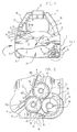
- Fig. 1 shows the ribbon cartridge 1 of this invention having a top wall or cover 3 (largely not shown) and a bottom wall or cover 5 as well as parallel side walls 7 which form a largely closed cartridge 1 with top wall 3 parallel to bottom wall 5.
- An internal wall 9 extends between top wall 3 and bottom wall 5 to form a chamber 11 in which conventional woven fabric printer ribbon 13 is tightly forced or stuffed.
- Cartridge 1 has ribbon guide arm 15 from which ribbon 13 exits chamber 11 and opposing ribbon guide arm 17 through which ribbon again enters cartridge 1 and contacts a guide post 19 in guide arm 17 and then contacts guide post 21 outside of chamber 11.
- a flat spring 23 of the approximate width of ribbon 13 is held in guide arm 15 by being positioned in notches in a hollow, rectangular post 25 so that the flat surface of spring 23 presses ribbon 13 against a flat surface 27 in arm 15, to frictionally meter exit of ribbon 13 as is essentially conventional.
- Arm 15 and arm 17 are connected by a bracket 28 to provide added physical stability.
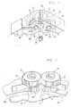
- Drive roller 29 (Fig.2) having a top flange 31 is mounted across from entrance arm 15 at the corner of cartridge 1 opposite arm 17.
- Drive roller 29 (Fig. 2) has top flange 31 (shown partially in phantom in Fig. 2) for manual feeding of ribbon 13.
- Roller 29 has teeth 33 which drive a pinch roller 35 by meshing with the teeth 37 of roller 35.
- a pinch roller 39 has teeth 41 which engage and mesh with teeth 37.
- Pinch rollers 35 and 39 are identical.
- the teeth 33, 37 and 41 all have the same standard involute gear profile in cross section. Involute teeth do not have pointed ends, which tend to fold the ribbon.
- the involute profile provides constant speed and force between meshed teeth, as is well established.
- Ribbon 13 is pinched or nipped between roller 35 and roller 39 where teeth 37 and 41 come together. Teeth 37 of roller 35 engage with and mesh with teeth 33 of drive roller 29, while roller 39 and roller 29 are separated, permitting ribbon 13 to be guided by the surface of teeth 41 to where ribbon 13 is pinched between roller 35 and roller 39.
- drive roller 29 has a cylindrical extension 41 which extends out of the bottom wall 5 of cartridge 1.
- Extension 41 has internal, closely spaced ridges 43 extending longitudinally along the internal axis of extension 41 from the lower edge, suited to receive a drive member 45 of a printer to which cartridge 1 is installed for use.
- Extension 43 and its cooperation with drive member 45 is identical to existing subject matter for which it was a design objective that this cartridge be compatible.
- rollers 35 and 39 have central regions 40a, 40b respectively having no teeth 37, 41, and wall 9 forms spaced abutments 47 and 49 occupying those central regions 40a, 40b respectively.
- Abutments 47 and 49 are strippers which prevent ribbon 13 from wrapping around either of the rollers 35, 39. Such stripper members are entirely conventional.
- abutment 49 is flexed into chamber 11 to provide space during assembly to position roller 39 after rollers 29 and 35 have been positioned as shown in Fig. 2. Openings 50a and 50b in bottom wall 5 under abutments 47 and 49 respectively permit mold access to fabricate abutments 47 and 49 and are not significant in the operation of the cartridge 1.
- a flat spring 51 of about the width of ribbon 13 is held in an L-shaped extension 53 on the inside of wall 7 and an L-shaped extension 55 on the inside of wall 7 at its other end.
- An extension 57 of spring 51 fits in the central region 40a (having no teeth) of roller 35, and is flexed to firmly bias roller 35 toward roller 39.
- bottom wall 5 is formed in an oblong extension 59 which just fits and receives a bottom shaft 61 (Fig. 3) of roller 35.
- extension 59 The long axis of extension 59 is directed to allow roller 35 to move generally tangentially to roller 29, so that teeth 33 remain engaged with teeth 37 as roller 35 moves because of enlargements of ribbon 13, such as those resulting from bends. When the ribbon returns to normal thickness, roller 35 is restored in position by spring member 57. (To provide a physical support against tipping of roller 35 as it moves along extension 59, top cover 3 has a depending straight ridge (not shown) parallel to extension 59 which engages the top shaft of roller 35 opposite roller 29.)
- a round extension 62 of bottom wall 5 loosely receives bottom shaft 63 of roller 39 and also a vertical shaft 64 from bottom cover 5 just fits within roller 39. These permit roller 39 to rotate, but not move bodily.
- rollers 35 and 39 are identical and each is symmetrical. No top or bottom need be found for insertion as they are identical.
- Chamber 11 is defined by walls 9 to be generally oval. Top wall 3 and bottom wall 5 are flat where they face chamber 11 except for a ridge on each of them to form a dam as discussed below.
- the height of chamber 11 is 8.6 mm, while the height of ribbon 13 is 7.94 mm, leaving a nominal 0.66 mm clearance within chamber 11.
- a wall portion 69 which is generally perpendicular to wall portion 9a and which leads to one side of a narrow slot 71 of width to permit only single strands of ribbon 13 to exit.
- the other side of slot 71 is defined by a wall 73 extending from the edge of cartridge 1.
- Walls 69 and 73 extend between top wall 3 and bottom wall 5.
- Walls 7a, 69, 73 (the cartridge wall opposite wall 69) and the dam with ridge 67 form a small chamber 74 which contains loosely packed ribbon 13 which has entered from chamber 11.
- Slot 71 is therefore immediately contiguous to wall portion 69 and is on the side of chamber 74 near wall portion 9a.
- Single strands of ribbon 13 in chamber 74 are pulled out through slot 71. Ribbon 13 extends unimpeded from slot 71 to the surface 27 and is held against surface 27 by spring 23.
- cartridge 1 is installed on a printer which turns drive roller 29 clockwise (as viewed from above) to feed ribbon 13. Ribbon 13 is held between pinch rollers 35 and 39, and roller 35 is driven by roller 29. Ribbon 13 is thereby forced or stuffed into chamber 11. Chamber 11 is tightly filled with ribbon 13, which takes a generally random, folded configuration.
- the dam formed by ridge 67 being positioned near obstructive wall 9a, is effective to meter ribbon 13 to chamber 74, where ribbon 13 then smoothly exits slot 71. Ribbon 13 passes out of arm 15 to be used for printing in the region between arms 15 and 17. Ribbon 13 is normally connected end-to-end to be continuous and is used repeatedly until ink in ribbon 13 is depleted.
- This configuration permits both the drive roller 29 and the pinch roller 39 around which ribbon 13 is guided to be fixed in position within cartridge 1. Roller 35 is free to translate to accommodate bends and other high areas in ribbon 13.
Landscapes
- Impression-Transfer Materials And Handling Thereof (AREA)
Applications Claiming Priority (2)
| Application Number | Priority Date | Filing Date | Title |
|---|---|---|---|
| US07/175,893 US4840503A (en) | 1988-03-31 | 1988-03-31 | Stuffed chamber ribbon cartridge |
| US175893 | 1988-03-31 |
Publications (3)
| Publication Number | Publication Date |
|---|---|
| EP0336872A2 true EP0336872A2 (de) | 1989-10-11 |
| EP0336872A3 EP0336872A3 (en) | 1989-11-23 |
| EP0336872B1 EP0336872B1 (de) | 1993-04-28 |
Family
ID=22642098
Family Applications (1)
| Application Number | Title | Priority Date | Filing Date |
|---|---|---|---|
| EP89480036A Expired - Lifetime EP0336872B1 (de) | 1988-03-31 | 1989-02-28 | Bandkassette mit einem Raum für Schleifenspeicherung |
Country Status (5)
| Country | Link |
|---|---|
| US (1) | US4840503A (de) |
| EP (1) | EP0336872B1 (de) |
| JP (1) | JPH01257084A (de) |
| CA (1) | CA1312774C (de) |
| DE (1) | DE68906190T2 (de) |
Cited By (2)
| Publication number | Priority date | Publication date | Assignee | Title |
|---|---|---|---|---|
| DE4008008A1 (de) * | 1989-03-13 | 1990-09-27 | Seikosha Kk | Farbbandkassette |
| EP0554490A1 (de) * | 1992-02-06 | 1993-08-11 | Caribonum Limited | Farbbandkassette |
Families Citing this family (2)
| Publication number | Priority date | Publication date | Assignee | Title |
|---|---|---|---|---|
| JP4440943B2 (ja) * | 2007-03-19 | 2010-03-24 | 株式会社沖データ | インクリボンカセット及び印刷装置 |
| DE202011100668U1 (de) * | 2011-05-11 | 2012-08-14 | Herma Gmbh | Motorischer Vorroller mit Schlaufenbildner |
Family Cites Families (27)
| Publication number | Priority date | Publication date | Assignee | Title |
|---|---|---|---|---|
| BE786567A (fr) * | 1971-07-22 | 1973-01-22 | Siemens Ag | Dispositif de fixation d'un magasin pour ruban encre sur un dispositif d'impression |
| US3974906A (en) * | 1972-02-25 | 1976-08-17 | Xerox Corporation | Endless loop ribbon cartridge with random storage |
| US3814231A (en) * | 1973-04-24 | 1974-06-04 | Scm Corp | Stuffed ribbon cartridge |
| US3989132A (en) * | 1974-08-26 | 1976-11-02 | General Electric Company | Ribbon storage and transport mechanism |
| IT1024841B (it) * | 1974-11-18 | 1978-07-20 | Olivetti Ing C S P A | Cartuccia per un nastro inchiostra to senza fine di macchine per ufficio soriventi |
| US4053042A (en) * | 1974-12-06 | 1977-10-11 | Qume Corporation | Endless ribbon cartridge |
| US3994383A (en) * | 1975-02-05 | 1976-11-30 | Ncr Corporation | Stuffed ribbon cartridge |
| DE2618379B2 (de) * | 1976-04-27 | 1980-04-30 | Triumph Werke Nuernberg Ag, 8500 Nuernberg | Endlosfarbbandkassette für Schreibund ähnliche Maschinen |
| IT1093436B (it) * | 1976-12-29 | 1985-07-19 | Olivetti C Ing E C Spa | Cartuccia per un nastro inchiostrato di macchine scriventi e maccanismo per l avanz amento di detto nastro |
| US4405247A (en) * | 1978-06-05 | 1983-09-20 | Centronics Data Computer Corp. | Fully self-contained disposable cartridge for inked ribbons and the like |
| US4229112A (en) * | 1978-12-22 | 1980-10-21 | International Business Machines Corporation | Random stuffer ribbon cartridge with improved ribbon exit control |
| JPS6012948B2 (ja) * | 1979-01-24 | 1985-04-04 | アルプス電気株式会社 | インクリボンカ−トリツジ |
| DE2965495D1 (en) * | 1979-06-01 | 1983-07-07 | Kienzle Apparate Gmbh | Ink-ribbon mechanism and cartridge |
| JPS56290A (en) * | 1979-06-11 | 1981-01-06 | Sumitomo Alum Smelt Co Ltd | Electrolytic furnace for production of aluminum |
| US4408910A (en) * | 1980-11-25 | 1983-10-11 | Oki Electric Industry Co., Ltd. | Ink ribbon protecting mechanism in ink ribbon cartridge |
| US4388006A (en) * | 1981-03-03 | 1983-06-14 | Durango Systems, Inc. | Printing ribbon cartridge |
| JPS5836161U (ja) * | 1981-09-02 | 1983-03-09 | 株式会社ブリヂストン | インクリボンカセツト |
| JPS58122887A (ja) * | 1982-01-18 | 1983-07-21 | Silver Seiko Ltd | タイプライタ−のモ−タ駆動装置 |
| US4449838A (en) * | 1982-07-28 | 1984-05-22 | Matsushita Electric Industrial Co., Ltd. | Ink ribbon cassette for printer |
| DE3382488D1 (de) * | 1982-10-13 | 1992-02-13 | Turbon International Ag | Antriebsmechanismen fuer farbbandkassetten. |
| SE442183B (sv) * | 1983-03-07 | 1985-12-09 | Ericsson Telefon Ab L M | Brytorgan for fergband vid skrivmaskiner och dylikt |
| US4523868A (en) * | 1983-07-18 | 1985-06-18 | International Business Machines Corporation | Ribbon feed cartridge |
| JPS6044384A (ja) * | 1983-08-22 | 1985-03-09 | エヌ・シー・アール・コーポレーション | インキ供給機構付リボン・カ−トリツジ |
| JPS60171357U (ja) * | 1984-04-23 | 1985-11-13 | 沖電気工業株式会社 | リボンカ−トリツジ |
| GB8527594D0 (en) * | 1985-11-08 | 1985-12-11 | Data Recording Instr Co | Ribbon cassette for printers |
| GB2184998B (en) * | 1986-01-08 | 1990-03-28 | Canon Kk | Ink ribbon cassette |
| IT1187942B (it) * | 1986-02-28 | 1987-12-23 | Olivetti & Co Spa | Cartucce per nastro inchiostrato con dispositivo di reinchiostrazione |
-
1988
- 1988-03-31 US US07/175,893 patent/US4840503A/en not_active Expired - Lifetime
-
1989
- 1989-01-20 CA CA000588784A patent/CA1312774C/en not_active Expired - Fee Related
- 1989-02-06 JP JP1025968A patent/JPH01257084A/ja active Granted
- 1989-02-28 DE DE89480036T patent/DE68906190T2/de not_active Expired - Fee Related
- 1989-02-28 EP EP89480036A patent/EP0336872B1/de not_active Expired - Lifetime
Cited By (2)
| Publication number | Priority date | Publication date | Assignee | Title |
|---|---|---|---|---|
| DE4008008A1 (de) * | 1989-03-13 | 1990-09-27 | Seikosha Kk | Farbbandkassette |
| EP0554490A1 (de) * | 1992-02-06 | 1993-08-11 | Caribonum Limited | Farbbandkassette |
Also Published As
| Publication number | Publication date |
|---|---|
| EP0336872A3 (en) | 1989-11-23 |
| JPH01257084A (ja) | 1989-10-13 |
| EP0336872B1 (de) | 1993-04-28 |
| US4840503A (en) | 1989-06-20 |
| JPH0464516B2 (de) | 1992-10-15 |
| DE68906190D1 (de) | 1993-06-03 |
| DE68906190T2 (de) | 1993-10-07 |
| CA1312774C (en) | 1993-01-19 |
Similar Documents
| Publication | Publication Date | Title |
|---|---|---|
| FI61428B (fi) | Bandkassett | |
| US4383775A (en) | Ribbon shield | |
| EP0240112B1 (de) | Farbbandkassette mit Nachtränkvorrichtung | |
| EP0336872B1 (de) | Bandkassette mit einem Raum für Schleifenspeicherung | |
| KR970706129A (ko) | 잉크제트 프린터의 카트리지 및 잉크제트 프린터(Cartridge of ink-jet printer and ink-jet printer) | |
| JPH06328821A (ja) | テープカセット | |
| US4388006A (en) | Printing ribbon cartridge | |
| EP0043719B1 (de) | Bandpatrone | |
| US4227820A (en) | Endless ink-ribbon cartridge | |
| US4074800A (en) | Endless printer ribbon cartridge apparatus | |
| ITMI980065A1 (it) | Dispositivo erogatore di asciugamani di carta ricavati per taglio manuale da un nastro continuo | |
| EP0004047B1 (de) | Farbbandkassette | |
| JPH043824Y2 (de) | ||
| US4026492A (en) | Ribbon tension control means | |
| EP0034212B1 (de) | Farbbandführung für eine Farbbandkassette in einer Schreibmaschine | |
| EP0092291B1 (de) | Drucker mit schalldämpfender Papiertransportrolle | |
| EP0053685A2 (de) | Einwegfarbbandkassette mit einem zerbrechlichen Widerstandselement zum Verlangsamen der Seitenauslenkung der Aufnahmespule | |
| US4749293A (en) | Ribbon cassette for printers | |
| US4229112A (en) | Random stuffer ribbon cartridge with improved ribbon exit control | |
| US4212420A (en) | Ribbon storage device | |
| US4286887A (en) | Endless ribbon cassette | |
| EP0041579B1 (de) | Anordnung zum zusammenpacken eines farbbandes für einen drucker | |
| EP0396819A2 (de) | Passive Papieraufnahme für Papierrollen | |
| EP0231645A2 (de) | Bandkassette | |
| CA1208152A (en) | Inked ribbon cartridge |
Legal Events
| Date | Code | Title | Description |
|---|---|---|---|
| PUAI | Public reference made under article 153(3) epc to a published international application that has entered the european phase |
Free format text: ORIGINAL CODE: 0009012 |
|
| PUAL | Search report despatched |
Free format text: ORIGINAL CODE: 0009013 |
|
| AK | Designated contracting states |
Kind code of ref document: A2 Designated state(s): BE CH DE ES FR GB IT LI NL SE |
|
| AK | Designated contracting states |
Kind code of ref document: A3 Designated state(s): BE CH DE ES FR GB IT LI NL SE |
|
| 17P | Request for examination filed |
Effective date: 19900120 |
|
| 17Q | First examination report despatched |
Effective date: 19910704 |
|
| RAP1 | Party data changed (applicant data changed or rights of an application transferred) |
Owner name: LEXMARK INTERNATIONAL, INC. |
|
| 111Z | Information provided on other rights and legal means of execution |
Free format text: BE CH DE ES FR GB IT LI NL SE |
|
| GRAA | (expected) grant |
Free format text: ORIGINAL CODE: 0009210 |
|
| AK | Designated contracting states |
Kind code of ref document: B1 Designated state(s): BE CH DE ES FR GB IT LI NL SE |
|
| PG25 | Lapsed in a contracting state [announced via postgrant information from national office to epo] |
Ref country code: IT Free format text: LAPSE BECAUSE OF FAILURE TO SUBMIT A TRANSLATION OF THE DESCRIPTION OR TO PAY THE FEE WITHIN THE PRE;WARNING: LAPSES OF ITALIAN PATENTS WITH EFFECTIVE DATE BEFORE 2007 MAY HAVE OCCURRED AT ANY TIME BEFORE 2007. THE CORRECT EFFECTIVE DATE MAY BE DIFFERENT FROM THE ONE RECORDED.SCRIBED TIME-LIMIT Effective date: 19930428 Ref country code: ES Free format text: THE PATENT HAS BEEN ANNULLED BY A DECISION OF A NATIONAL AUTHORITY Effective date: 19930428 Ref country code: SE Effective date: 19930428 Ref country code: NL Effective date: 19930428 Ref country code: BE Effective date: 19930428 |
|
| REF | Corresponds to: |
Ref document number: 68906190 Country of ref document: DE Date of ref document: 19930603 |
|
| ET | Fr: translation filed | ||
| NLV1 | Nl: lapsed or annulled due to failure to fulfill the requirements of art. 29p and 29m of the patents act | ||
| PLBE | No opposition filed within time limit |
Free format text: ORIGINAL CODE: 0009261 |
|
| STAA | Information on the status of an ep patent application or granted ep patent |
Free format text: STATUS: NO OPPOSITION FILED WITHIN TIME LIMIT |
|
| 26N | No opposition filed | ||
| REG | Reference to a national code |
Ref country code: GB Ref legal event code: IF02 |
|
| PGFP | Annual fee paid to national office [announced via postgrant information from national office to epo] |
Ref country code: FR Payment date: 20040219 Year of fee payment: 16 |
|
| PGFP | Annual fee paid to national office [announced via postgrant information from national office to epo] |
Ref country code: CH Payment date: 20040223 Year of fee payment: 16 |
|
| PGFP | Annual fee paid to national office [announced via postgrant information from national office to epo] |
Ref country code: GB Payment date: 20040225 Year of fee payment: 16 |
|
| PGFP | Annual fee paid to national office [announced via postgrant information from national office to epo] |
Ref country code: DE Payment date: 20040331 Year of fee payment: 16 |
|
| PG25 | Lapsed in a contracting state [announced via postgrant information from national office to epo] |
Ref country code: LI Free format text: LAPSE BECAUSE OF NON-PAYMENT OF DUE FEES Effective date: 20050228 Ref country code: GB Free format text: LAPSE BECAUSE OF NON-PAYMENT OF DUE FEES Effective date: 20050228 Ref country code: CH Free format text: LAPSE BECAUSE OF NON-PAYMENT OF DUE FEES Effective date: 20050228 |
|
| PG25 | Lapsed in a contracting state [announced via postgrant information from national office to epo] |
Ref country code: DE Free format text: LAPSE BECAUSE OF NON-PAYMENT OF DUE FEES Effective date: 20050901 |
|
| REG | Reference to a national code |
Ref country code: CH Ref legal event code: PL |
|
| GBPC | Gb: european patent ceased through non-payment of renewal fee |
Effective date: 20050228 |
|
| PG25 | Lapsed in a contracting state [announced via postgrant information from national office to epo] |
Ref country code: FR Free format text: LAPSE BECAUSE OF NON-PAYMENT OF DUE FEES Effective date: 20051031 |
|
| REG | Reference to a national code |
Ref country code: FR Ref legal event code: ST Effective date: 20051031 |