EP0336870A2 - Drucker mit Vorrichtung zum Einstellen der Schlagweite eines Druckkopfes - Google Patents
Drucker mit Vorrichtung zum Einstellen der Schlagweite eines Druckkopfes Download PDFInfo
- Publication number
- EP0336870A2 EP0336870A2 EP89480034A EP89480034A EP0336870A2 EP 0336870 A2 EP0336870 A2 EP 0336870A2 EP 89480034 A EP89480034 A EP 89480034A EP 89480034 A EP89480034 A EP 89480034A EP 0336870 A2 EP0336870 A2 EP 0336870A2
- Authority
- EP
- European Patent Office
- Prior art keywords
- printhead
- platen
- see
- support means
- gear
- Prior art date
- Legal status (The legal status is an assumption and is not a legal conclusion. Google has not performed a legal analysis and makes no representation as to the accuracy of the status listed.)
- Granted
Links
Images

Classifications
-
- B—PERFORMING OPERATIONS; TRANSPORTING
- B41—PRINTING; LINING MACHINES; TYPEWRITERS; STAMPS
- B41J—TYPEWRITERS; SELECTIVE PRINTING MECHANISMS, i.e. MECHANISMS PRINTING OTHERWISE THAN FROM A FORME; CORRECTION OF TYPOGRAPHICAL ERRORS
- B41J25/00—Actions or mechanisms not otherwise provided for
- B41J25/304—Bodily-movable mechanisms for print heads or carriages movable towards or from paper surface
- B41J25/308—Bodily-movable mechanisms for print heads or carriages movable towards or from paper surface with print gap adjustment mechanisms
- B41J25/3086—Bodily-movable mechanisms for print heads or carriages movable towards or from paper surface with print gap adjustment mechanisms with print gap adjustment means between the print head and its carriage
-
- B—PERFORMING OPERATIONS; TRANSPORTING
- B41—PRINTING; LINING MACHINES; TYPEWRITERS; STAMPS
- B41J—TYPEWRITERS; SELECTIVE PRINTING MECHANISMS, i.e. MECHANISMS PRINTING OTHERWISE THAN FROM A FORME; CORRECTION OF TYPOGRAPHICAL ERRORS
- B41J25/00—Actions or mechanisms not otherwise provided for
- B41J25/304—Bodily-movable mechanisms for print heads or carriages movable towards or from paper surface
- B41J25/308—Bodily-movable mechanisms for print heads or carriages movable towards or from paper surface with print gap adjustment mechanisms
Definitions
- This invention relates to a printer having its printhead spaced from its platen in accordance with the thickness of the recording medium on which printing is to occur and, more particularly, to a printer in which the spacing between the printhead and the platen may be adjusted either automatically or manually in accordance with the thickness of the recording medium on which printing is to occur.
- the spacing or gap between a platen and a printhead is very small and critical.
- the spacing may be between 0.406 mm and 0.812 mm depending upon the thickness of the recording medium on which printing is to occur.
- a thicker recording medium such as an envelope, for example, would require a greater gap than a single sheet of paper.
- a remote control signal from the PC is required to change the gap or spacing between the printhead and the platen when the thickness of the recording medium changes with respect to the prior recording medium on which printing has occurred. This is necessary to insure the desired print quality.
- the printer it is desired for the printer to be capable of having the gap or spacing between the printhead and the platen to be manually adjusted by a user when the printer is not under control the PC. This enables a user to have a plurality of selections as to the size of the gap or spacing.
- the mechanism of the aforesaid Veale and Kikuchi et al patents are not capable of having either manual or automatic adjustment of the gap as is required when seeking to remotely control the size of the gap while still enabling a user to manually control the gap size when desired.
- the printer of the present invention satisfactorily solves the foregoing problem through having a mechanism capable of enabling the gap or space between a printhead and a platen to be either automatically or manually adjusted.
- the printer automatically moves to its maximum gap or space when printing is to be on an envelope or a multi-part form in response to a control signal from a host data processor (PC) and to its minimum gap or spacing when printing is to be on a single sheet of paper in response to a control signal from the PC.
- PC host data processor
- the printer of the present invention accomplishes this through utilizing its ribbon drive motor to rotate a gear train to cause movement of a portion of the carrier having the printhead thereon to move the printhead closer or further from the platen.
- the printer of the present invention also is capable of having the portion of the carrier having the printhead thereon moved through a separate gearing arrangement being manually moved by a handle to activate a portion of the gear train.
- An object of this invention is to provide a printer having a mechanism for changing the gap or spacing between a printhead and a platen.
- Another object of this invention is to provide a printer in which the gap or spacing between a printhead and a platen may be controlled either automatically or manually.
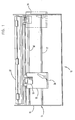
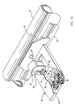
- a printer 10 including a frame 11 supporting a platen 12.
- the frame 11 includes a right side plate 14 and a left side plate 15 substantially parallel to each other.
- a front guide rail 16 extends between the sides plates 14 and 15, and a rear guide rail 17 extends between the side plates 14 and 15.
- the carrier 18 includes a first portion 20 (see FIG. 5), which supports the printhead 19 and is slidably supported on the front guide rail 16 for movement parallel to the longitudinal axis of the platen 12.
- a shoe 21 (see FIG. 6), which constitutes a second portion of the carrier 18, is slidably supported on the rear guide rail 17.
- a screw 22 holds the shoe 21 on the rear guide rail 17 so that the shoe 21 can only move axially along the rear guide rail 17 and parallel to the longitudinal axis of the platen 12 (see FIG. 1).
- the shoe 21 (see FIG. 6) rotatably supports a jacking gear 23, which has twenty-six teeth, having a threaded shaft 24, which is threaded into an adjustment sleeve 25, integral therewith.
- the adjustment sleeve 25 is attached to the first portion 20 of the carrier 18 by a locking tab 26, which is secured to the first portion 20 of the carrier 18 by a locking screw 27, bearing against a flange 28 on the adjustment sleeve 25. Accordingly, the threaded shaft 24 and the adjustment sleeve 25 cooperate to connect the first portion 20 of the carrier 18 and the shoe 21 of the carrier 18 to each other while permitting slight relative movement therebetween to enable changing or adjusting of the spacing of the printhead 19 (see FIG. 5) from the platen 12.
- Rotation of the jacking gear 23 causes pivoting of the first portion 20 of the carrier 18 about the front guide rail 16 to change or adjust the gap or spacing between the printhead 19 (see FIG. 5) and the platen 12.
- a printer microprocessor 30 checks the options port to determine if the dual bin automatic sheet feeder with the optional envelope bin is installed. If it is, the printer microprocessor 30 causes the gap between the printhead 19 (see FIG. 5) and the platen 12 to be set to the default position for a sheet of paper, specified by a user by settings of switches, during the initialization process.
- a recording medium of an increased thickness such as an envelope, for example, is to be positioned on the platen 12 for printing from the printhead 19 after a thinner recording medium such as a sheet of paper, for example, has been positioned on the platen 12
- the jacking gear 23 (see FIG. 6) is automatically rotated to shift the first portion 20 of the carrier 18 relative to the shoe 21 to increase the gap or space between the platen 12 (see FIG. 5) and the printhead 19.
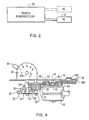
- a control signal is supplied from the PC 31 (see FIG. 2), which comprises a host data processor, to the microprocessor 30 of the printer 10 (see FIG. 1).
- the printer 10 may be utilized with additional PCs besides the PC 31 (see FIG. 2) and one additional PC is shown in phantom in FIG. 2.
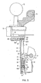
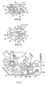
- the printer microprocessor 30 When the microprocessor 30 receives the control signal from the PC 31, the printer microprocessor 30 causes the carrier 18 (see FIG. 1) to move along the guide rails 16 and 17 towards the right side plate 14 of the frame 11 by activation of the transport motor for the carrier 18. This motion of the carrier 18 causes a finger 32 (see FIG. 5) of a first portion 33 of a rotatably mounted shift arm 34 (see FIG. 3) to engage the right side plate 14. This also is shown in phantom in FIG. 1.
- the first portion 33 (see FIG. 5) of the shift arm 34 includes a flat portion 35, which is substantially parallel to a flat portion 36 of a second portion 37 of the shift arm 34.
- a rivet 38 connects the flat portions 35 and 36 to each other.
- a support stud 39 for a gear 40 which has forty-one teeth, also connects the flat portions 35 and 36 to each other.
- the shift arm 34 (see FIG. 3) rotates about the axis of a shaft 41 of a motor 42 (see FIG. 4), which drives a ribbon in a ribbon cartridge (not shown) supported by the first portion 20 of the carrier 18.
- the flat portion 36 (see FIG. 5) of the second portion 37 of the shift arm 34 is rotatably supported on the outer surface of a bushing 42A on the housing of the motor 42 for the shaft 41.
- the flat portion 35 of the first portion 33 of the shift arm 34 is rotatably supported on a bushing 42B extending downwardly from the first portion 20 of the carrier 18.
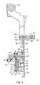
- the motor 42 (see FIG. 4), which is supported on the first portion 20 of the carrier 18, has a pinion gear 43, which has twelve teeth, fixed to the shaft 41.
- the pinion gear 43 is always in engagement with the gear 40 (see FIG. 3) on the shift arm 34.
- the gear 40 is in engagement with an output pinion gear 44, which has twenty and is rotatably supported on a stud 45 extending downwardly from the first portion 20 of the carrier 18.
- the output pinion gear 44 meshes with a ribbon drive gear 46.
- the ribbon drive gear 46 includes a second ribbon drive gear 47 meshing with a third ribbon drive gear 48, which is supported from the first portion 20 of the carrier 18 by a stud 48A having a gear 48B (see FIG. 4) above the upper surface of the first portion 20 of the carrier 18.
- the gear 48B advances the ribbon past the print position through driving a gear attached to a spool of the ribbon cartridge, which is supported on the upper surface of the first portion 20 of the carrier 18.
- the jacking gear 23 (see FIG. 3) is driven from the output pinion gear 49 through a gear train, which includes a compound idler gear 51 and a compound gear 52.
- the compound idler gear 51 is supported on the first portion 20 of the carrier 18 by a stud 53 (see FIG. 4) extending downwardly therefrom, and the compound gear 52 is supported on the first portion 20 of the carrier 18 by a stud 54 extending downwardly therefrom.
- the compound idler gear 51 includes an upper idler gear 55, which has fifty teeth, meshing with the output pinion gear 49.
- the compound idler gear 51 has a lower idler gear 56, which has thirty-two teeth, meshing with an intermediate gear 57, which has forty-five teeth, of the compound gear 52.
- the compound gear 52 has its lower gear 58 (see FIG. 6) meshing with the jacking gear 23.
- the compound gear 52 also has an upper bevel gear 59, which has twenty-seven teeth, meshing with a bevel gear 60, which has eighteen teeth, on one end of a shaft 61.
- the shaft 61 has a spur gear 62, which has seventeen teeth, on its opposite end.
- the shaft 61 is supported on the first portion 20 of the carrier 18 by journals 62A (see FIG. 6) and 62B adjacent the gears 60 and 62, respectively.
- the gear 62 meshes with a sector gear 63, which has fifty-three teeth, on an inner end of a handle 64.
- the handle 64 cooperates with indicia on an upstanding plate 65, which is integral with the first portion 20 of the carrier 18 and has the handle 64 rotatably mounted thereon by a stud 65A, to indicate the position of the printhead 19 (see FIG. 5) with respect to the platen 12.
- position 1 on the plate 65 indicates the minimum gap or spacing between the platen 12 (see FIG. 5) and the printhead 19
- position 5 (see FIG. 4) on the plate 65 identifies the maximum spacing between the platen 12 (see FIG. 5) and the printhead 19.
- Positins 2,3, and 4 on the plate 65 indicate gaps intermediate the minimum and maximum gaps.
- the handle 64 (see FIG. 6), which is held against the plate 65 by a flange 65B on the end of the shaft 61 bearing against the gear 63 on the inner end of the handle 64, may be grasped by the user to rotate the jacking gear 23 through the gears 63 and 62, the shaft 61, the bevel gears 60 and 59, and the gear 58.
- the spacing or gap between the printhead 19 (see FIG. 5) and the platen 12 may be manually adjusted.
- the finger 32 of the first portion 33 (see FIG. 3) of the shift arm 34 engages the right side plate 14 during advancement of the carrier 18 to the right by its transport motor, the finger 32 (see FIG. 5) deflects because the first portion 33 of the shift arm 34 is formed of a resilient metal so that the finger 32 functions as a cantilever spring.
- the second portion 37 of the shift arm 34 is formed of a substantially rigid metal so that the maximum deflection of the finger 32 is limited by a stop 65C on the second portion 37 of the shift arm 34.
- the torsion spring 66 acts against one end of a tab 67 of the flat portion 35 of the first portion 33 of the shift arm 34.
- the torsion spring 66 has its other end acting against a curved surface 68 of the first poriton 20 of the carrier 18.
- the torsion spring 66 has plurality of coils wrapped around a stud 69 extending downwardly from the first portion 20 of the carrier 18.
- the shift arm 34 continues to rotate counterclockwise until a point is reached at which this counterclockwise moment, which is produced by the finger 32 (see FIG. 5) of the shift arm 34 engaging the right side plate 14, is greater then the moment produced by the torsion spring 66 (see FIG. 3).
- the shift arm 34 is rotated counterclockwise until a stop 70 on the shift arm 34 engages the stud 50, which rotatably supports the output pinion gear 49.
- the gear 40 is meshing with the output pinion gear 49 to cause rotation of the jacking gear 23 through the gear train of the compound idler gear 51 and the compound gear 52 when the motor 42 (see FIG. 4) is energized.
- the stop 70 (see FIG. 3) and the stud 50 insure proper meshing center distance between the gears 40 and 49 to avoid a hard engagement between the teeth of the gears 40 and 49 when the shift arm 34 rotates counterclockwise.
- the spring rates of the finger 32 (see FIG. 5) and the torsion spring 66 (see FIG. 3) are selected to prevent impact of the stop 70 on the stud 50 when there is counterclockwise rotation of the shift arm 34.
- the transport motor of the carrier 18 is the source of force to mitigate against the restoring moment of the torsion spring 66, the transport motor for the carrier 18 can have a very low holding current at this time because the restoring moment is relatively low when the shift arm 34 is in its activated position. While the transport back-drive friction, which is the friction that must be overcome to push the carrier 18 away from the right side plate 14, is almost sufficient to hold the carrier 18 against the right side plate 14, the holding of the carrier 18 against the right side plate 14 should not depend solely upon this friction. Accordingly, the transport motor for the carrier 18 should draw a little current to insure that the carrier 18 remains in the position in which the shift arm 34 is in its activated position.
- the motor 42 (see FIG. 4) is energized for a sufficient period of time to insure that the compound gear 52 can be rotated from the position in which one end of the arcuate slot 73 (see FIG. 9) engages the tab 71 until the other end of the arcuate slot 73 engages the tab 71.
- the motor 42 (see FIG. 4) is energized after the shift arm 34 is in its activated position of FIG. 3 and the shaft 41 of the motor 42 (see FIG. 4) has rotated clockwise (as viewed in FIG. 3) to increase the gap between the printhead 19 (see FIG. 5) and the platen 12 to its maximum, there is a reaction torque on the shift arm 34 (see FIG.
- the motor 42 (see FIG. 4) is turned under control of the printer microprocessor 30 (see FIG. 2) when the carrier 18 (see FIG. 3) ceases to move because of the shift arm 34 engaging the right side plate 14.
- the shift arm 34 (see FIG. 7) is in its inactivated position so that the gear 40 is in mesh with the output pinion gear 44 to drive the ribbon.
- the holding moment from the toggle spring 66 on the shift arm 34 is a maximum.
- the shaft 41 of the motor 42 (see FIG. 4) rotates clockwise (as viewed in FIG. 7) when the ribbon is driven.
- the reaction torque on the shift arm 34 (see FIG. 7) from the rotation of the motor 42 (see FIG. 4) aids in maintaining meshing between the gears 40 (see FIG. 7) and 44.
- the printhead 19 (see FIG. 3) is held in any of the positions to which it is moved automatically or manually by a detent mechanism.
- the detent mechanism includes an upstanding spherical dimple 76 (see FIG. 9) on the end of the flat detent spring 72 remote from its free end fitting on the stud 53.
- the compound gear 52 has five detent grooves 77, 78, 79, 80, and 81 in its bottom surface for cooperation with the spherical dimple 76 on the flat detent spring 72.
- the detent groove 77 is adjacent one end of the arcuate slot 73 in the bottom of the compound gear 52
- the detent groove 81 is adjacent the other end of the arcuate slot 73.
- the groove 77 corresponds to position 1 of the printhead 19 (see FIG. 3)
- the groove 78 corresponds to position 2 on the plate 65 (see FIG. 4)
- the groove 79 corresponds to position 3 on the plate 65 (see FIG. 4)
- the groove 80 corresponds to position 4 on the plate 65 (see FIG. 4)
- the groove 81 corresponds to position 5 on the plate 65 (see FIG. 4).
- the handle 64 (see FIG. 4) preferably is moved to positions halfway between each adjacent pair of positions 1, 2, 3, 4, and 5 on the plate 65. This would necessitate four additional detent grooves (not shown) being in the bottom surface of the compound gear 52 (see FIG. 9) in addition to the detent grooves 77-81.
- the radial distance from the center of the stud 54 (see FIG. 9) to the point of application of the detent force by the spherical dimple 76 on the flat detent spring 72 engaging one of the grooves 77-81 is as large as practical to provide a maximum detent torque.
- the radius of the spherical dimple 76 is larger than the radius of any of the grooves 77-81 to provide a sharp detent feel when the spherical dimple 76 enters one of the grooves 77-81.
- a user can feel the entrance of the spherical dimple 76 (see FIG. 9) into each of the grooves 77-81 whereby the user will stop movement of the handle 64 (see FIG. 4) when the spherical dimple 76 (see FIG. 9) enters the one of the grooves 77-81 corresponding to the position at which the handle 64 (see FIG. 4) is to be disposed.
- the initial minimum space or gap between the platen 12 (see FIG. 5) and the printhead 19 is set through loosening the locking screw 27 (see FIG. 6) and turning the adjustment sleeve 25 with a screw driver extending into a slot 82 in the end of the adjustment sleeve 25. Since the threaded shaft 24 is rotationally stationary during this adjustment, the threaded connection of the threaded shaft 24 with the adjustment sleeve 25 draws the threaded shaft 24 up or down into the adjustment sleeve 25 depending on the direction in which the adjustment sleeve 25 is turned. This changes the distance between the shoe 21 and the first portion 20 of the carrier 18 to change the space or gap between the printhead 19 (see FIG. 5) and the platen 12. Then, the locking tab 26 (see FIG. 6) is tightened against the flange 28 of the adjustment sleeves 25 by the locking screw 27.
- the PC 31 sends a control signal to the printer microprocessor 31 that a recording medium with a greater thickness such as an envelope, for example, is to be utilized rather than a single sheet of paper or vice versa. If the gap between the platen 12 (see FIG. 5) and the printhead 19 is a minimum, then the control signal would be for a recording medium with a greater thickness whereby the gap between the platen 12 and the printhead 19 will be increased to its maximum.
- This control signal to the printer microprocessor 30 causes the transport motor of the carrier 18 (see FIG. 3) to move the carrier 18 to the right until the finger 32 (see FIG. 5) of the shift arm 34 engages the right side plate 14. This produces counterclockwise (as view in FIG. 3) rotation of the shift arm 34 (see FIG. 3) to move the gear 40 into engagement with the output pinion gear 49.
- the motor 42 (see FIG. 4) is energized in one direction to cause rotation of the jacking gear 23 (see FIG. 6) to move the first portion 20 of the carrier 18 toward the shoe 21 by pivoting the first portion 20 of the carrier 18 clockwise about the front guide rail 16.
- the number of pulses to the motor 42 (see FIG. 4), which is a stepping motor, is sufficient to drive the compound gear 52 counterclockwise (as viewed in FIG. 9) until the end of the arcuate slot 73 (see FIG. 9) adjacent the detent groove 81 engages the tab 71.
- the printer microprocessor 30 causes the transport motor for the carrier 18 (see FIG. 3) to move the carrier 18 to the left to its position at which an envelope is loaded. This returns the shift arm 34 to its deactivated position of FIG. 7 so taht is no meshing engagement of the gear 40 with the output pinion gear 49.
- the PC 31 sends a control signal to the printer microprocessor 30.
- the shift arm 34 rotates counterclockwise (as viewed in FIG. 3) to engage the gear 40 with the output pinion gear 49.
- the motor 42 (see FIG. 4) is energized for rotation in the opposite direction to rotate the compound gear 52 (see FIG. 9) clockwise (the opposite direction from that for producing a maximum gap) until the end of the arcuate slot 73 adjacent the detent groove 77 engages the tab 71 on the flat detent spring 72 as shown in FIG. 9.
- the printer microprocessor 30 After completion of clockwise rotation of the compound gear 52 to the position in which the gap between the platen 12 (see FIG. 5) and the printhead 19 is a minimum, the printer microprocessor 30 (see FIG. 2) causes energization of the transport motor for the carrier 18 (see FIG. 3) to move the carrier 18 to the left away from the right side plate 14. The carrier 18 is returned to the position at which a sheet of paper is loaded.
- a user may change the gap between the platen 12 (see FIG. 5) and the printhead 19 through manually rotating the handle 64 (see FIG. 4) to any of its other four positions.
- the spherical dimple 76 (see FIG. 9) on the flat detent spring 72 will be disposed in one of the others of the detent grooves 78-81 when the spherical dimple 76 is in the detent groove 77.
- the first portion 20 (see FIG. 10) of the carrier 18 has a card holder 83 mounted thereon adjacent the platen 12 to position the recording medium wrapped around the platen 12.
- the card holder 83 has an opening 84 for the wires of the printhead 19 to pass through and engage the recording medium to print thereon.
- the number of pulses to the motor 42 (see FIG. 4) for rotating the jacking gear 23 (see FIG. 6) could be other that the number for rotating the jacking gear 23 to pivot the first portion 20 of the carrier 18 between the positions producing the minimum and maximum gaps between the platen 12 (see FIG. 5) and the printhead 19. This would enable automatic positioning of the gap or spacing between the platen 12 (see FIG. 5) and the printhead 19 to intermediate positions such as those indentified as positions 2, 3, and 4 on the plate 65 (see FIG. 4). This would be controlled by the control signal from the PC 31 (see FIG. 2).
- the carrier 18 (see FIG. 5) has been shown and described as being moved relative to the platen 12 in directions parallel to the longitudinal axis of the platen 12, it should be understood that the platen 12 could be movable along its longitudinal axis and the carrier 18 would be stationary. It is only necessary that there be a relative motion between the platen 12 and the printhead 19 to produce printing along each line of a recording medium supported by the platen 12.
- An advantage of this invention is that the gap between a printhead and a platen may be automatically changed when the thickness of the recording medium changes. Another advantage of this invention is that it enables a printer which is used with at least one PC to have its gap between the platen and the printhead automatically set in response to a control signal from the PC. A further advantage of this invention is that the gap or spacing between a platen and a printhead of a printer may be set either automatically or manually.
Landscapes
- Common Mechanisms (AREA)
Applications Claiming Priority (2)
| Application Number | Priority Date | Filing Date | Title |
|---|---|---|---|
| US17909688A | 1988-04-08 | 1988-04-08 | |
| US179096 | 1988-04-08 |
Publications (3)
| Publication Number | Publication Date |
|---|---|
| EP0336870A2 true EP0336870A2 (de) | 1989-10-11 |
| EP0336870A3 EP0336870A3 (en) | 1990-03-28 |
| EP0336870B1 EP0336870B1 (de) | 1993-06-16 |
Family
ID=22655227
Family Applications (1)
| Application Number | Title | Priority Date | Filing Date |
|---|---|---|---|
| EP89480034A Expired - Lifetime EP0336870B1 (de) | 1988-04-08 | 1989-02-28 | Drucker mit Vorrichtung zum Einstellen der Schlagweite eines Druckkopfes |
Country Status (5)
| Country | Link |
|---|---|
| US (1) | US5131765A (de) |
| EP (1) | EP0336870B1 (de) |
| JP (1) | JP3025778B2 (de) |
| DE (1) | DE68907111T2 (de) |
| ES (1) | ES2043080T3 (de) |
Cited By (9)
| Publication number | Priority date | Publication date | Assignee | Title |
|---|---|---|---|---|
| EP0440464A1 (de) * | 1990-01-31 | 1991-08-07 | Brother Kogyo Kabushiki Kaisha | Mosaikdrucker mit Druckknopfeinstellung in Abhängigkeit von der Exzentrizität der Walze |
| EP0970816A3 (de) * | 1998-06-30 | 2000-06-07 | Canon Kabushiki Kaisha | Tintenstrahlaufzeichnungsgerät |
| WO2001089837A1 (en) * | 2000-05-23 | 2001-11-29 | Silverbrook Research Pty. Ltd. | Paper thickness sensor in a printer |
| US6488422B1 (en) | 2000-05-23 | 2002-12-03 | Silverbrook Research Pty Ltd | Paper thickness sensor in a printer |
| US6786658B2 (en) | 2000-05-23 | 2004-09-07 | Silverbrook Research Pty. Ltd. | Printer for accommodating varying page thicknesses |
| US6988840B2 (en) | 2000-05-23 | 2006-01-24 | Silverbrook Research Pty Ltd | Printhead chassis assembly |
| US7004652B2 (en) | 2000-05-23 | 2006-02-28 | Silverbrook Research Pty Ltd | Printer for accommodating varying page thickness |
| US7824021B2 (en) | 2000-05-23 | 2010-11-02 | Silverbrook Research Pty Ltd | Printhead assembly with printheads within a laminated stack which, in turn is within an ink distribution structure |
| US8702205B2 (en) | 2000-05-23 | 2014-04-22 | Zamtec Ltd | Printhead assembly incorporating ink distribution assembly |
Families Citing this family (7)
| Publication number | Priority date | Publication date | Assignee | Title |
|---|---|---|---|---|
| JP3488540B2 (ja) * | 1995-04-28 | 2004-01-19 | ブラザー工業株式会社 | ヘッドギャップ調整機構付印字装置 |
| US6231249B1 (en) * | 1999-09-15 | 2001-05-15 | International Business Machines Corporation | Duplex printer using a ribbon shifting mechanism |
| US6406110B1 (en) | 2000-09-01 | 2002-06-18 | Lexmark International, Inc | Mechanism to automate adjustment of printhead-to-print medium gap spacing on an imaging apparatus |
| US6487926B2 (en) * | 2001-05-02 | 2002-12-03 | Hewlett-Packard Company | Lock plate transmission |
| KR100437152B1 (ko) * | 2002-07-10 | 2004-06-25 | 삼성전자주식회사 | 잉크젯 프린터의 헤드갭 조절 장치 |
| DE602005022564D1 (de) | 2005-05-09 | 2010-09-09 | Agfa Graphics Nv | Transportvorrichtung für ein Aufzeichnungsmedium eines digitalen Druckers |
| US8757746B2 (en) | 2012-03-22 | 2014-06-24 | Xerox Corporation | Printhead positioning for web gap adjustment |
Family Cites Families (20)
| Publication number | Priority date | Publication date | Assignee | Title |
|---|---|---|---|---|
| US4023662A (en) * | 1974-12-19 | 1977-05-17 | Ing. C. Olivetti & C., S.P.A. | Arrangement for adjusting the spacing between a print head and a platen |
| JPS52152318A (en) * | 1976-06-14 | 1977-12-17 | Ricoh Kk | Printer |
| DE2752061C3 (de) * | 1977-11-22 | 1981-02-12 | Philips Patentverwaltung Gmbh, 2000 Hamburg | Einrichtung zur Einstellung des Abstandes eines Druckkopfes senkrecht zum Druckwiderlager |
| GB2029327B (en) * | 1978-09-02 | 1982-08-25 | Ibm | Printing apparatus |
| US4268177A (en) * | 1978-11-01 | 1981-05-19 | Plessey Peripheral Systems | Paper thickness adjusting mechanism for impact printer |
| US4261039A (en) * | 1979-10-19 | 1981-04-07 | International Business Machines Corporation | Microprocessor controlled positioning system |
| US4278020A (en) * | 1979-10-19 | 1981-07-14 | International Business Machines Corporation | Print wire actuator block assembly for printers |
| DE3014823C2 (de) * | 1980-04-15 | 1986-10-09 | Mannesmann AG, 4000 Düsseldorf | Matrixdrucker mit einem zur Druckspalteinstellung anstellbaren Druckkopf |
| JPS5796868A (en) * | 1980-12-08 | 1982-06-16 | Fujitsu Ltd | Dot printer |
| US4390292A (en) * | 1981-11-03 | 1983-06-28 | Zenith Radio Corporation | Means and method for compensating for print medium thickness in line printers |
| JPS59164174A (ja) * | 1983-03-09 | 1984-09-17 | Hitachi Ltd | プリンタ装置 |
| JPS6018377A (ja) * | 1983-07-11 | 1985-01-30 | Oki Electric Ind Co Ltd | ギヤツプ調整方式 |
| GB8405455D0 (en) * | 1984-03-01 | 1984-04-04 | Data Recording Instr Co | Printing apparatus |
| US4676675A (en) * | 1984-05-09 | 1987-06-30 | Brother Kogyo Kabushiki Kaisha | Media thickness compensating device for a printer |
| JPS612945U (ja) * | 1984-06-12 | 1986-01-09 | 沖電気工業株式会社 | プラテンギヤツプ調整機構 |
| US4652153A (en) * | 1984-07-25 | 1987-03-24 | Oki Electric Industry Co., Ltd. | Wire dot-matrix printer |
| US4738552A (en) * | 1985-03-11 | 1988-04-19 | Oki Electric Industry Co., Ltd. | Platen gap adjusting mechanism of printer |
| JPH0529885Y2 (de) * | 1986-09-11 | 1993-07-30 | ||
| JPS63112182A (ja) * | 1986-10-31 | 1988-05-17 | Toshiba Corp | プリンタ装置 |
| JPS648056A (en) * | 1987-06-30 | 1989-01-12 | Konishiroku Photo Ind | Printing head compression device |
-
1989
- 1989-01-30 JP JP01017843A patent/JP3025778B2/ja not_active Expired - Lifetime
- 1989-02-28 EP EP89480034A patent/EP0336870B1/de not_active Expired - Lifetime
- 1989-02-28 DE DE89480034T patent/DE68907111T2/de not_active Expired - Fee Related
- 1989-02-28 ES ES89480034T patent/ES2043080T3/es not_active Expired - Lifetime
- 1989-05-04 US US07/348,118 patent/US5131765A/en not_active Expired - Lifetime
Cited By (36)
| Publication number | Priority date | Publication date | Assignee | Title |
|---|---|---|---|---|
| EP0440464A1 (de) * | 1990-01-31 | 1991-08-07 | Brother Kogyo Kabushiki Kaisha | Mosaikdrucker mit Druckknopfeinstellung in Abhängigkeit von der Exzentrizität der Walze |
| US5088842A (en) * | 1990-01-31 | 1992-02-18 | Brother Kogyo Kabushiki Kaisha | Dot matrix printer having a print head position adjusting feature dependent on an eccentricity of a platen |
| EP0970816A3 (de) * | 1998-06-30 | 2000-06-07 | Canon Kabushiki Kaisha | Tintenstrahlaufzeichnungsgerät |
| US6273536B1 (en) | 1998-06-30 | 2001-08-14 | Canon Kabushiki Kaisha | Ink jet recording apparatus |
| US7210866B2 (en) | 2000-05-23 | 2007-05-01 | Silverbrook Research Pty Ltd | Printer having adjustable media support |
| US7325986B2 (en) | 2000-05-23 | 2008-02-05 | Silverbrook Research Pty Ltd | Printhead assembly with stacked ink distribution sheets |
| US6786658B2 (en) | 2000-05-23 | 2004-09-07 | Silverbrook Research Pty. Ltd. | Printer for accommodating varying page thicknesses |
| US6796731B2 (en) | 2000-05-23 | 2004-09-28 | Silverbrook Research Pty Ltd | Laminated ink distribution assembly for a printer |
| US8702205B2 (en) | 2000-05-23 | 2014-04-22 | Zamtec Ltd | Printhead assembly incorporating ink distribution assembly |
| US6984080B2 (en) | 2000-05-23 | 2006-01-10 | Silverbrook Research Pty Ltd | Laminated distribution structure |
| US6988840B2 (en) | 2000-05-23 | 2006-01-24 | Silverbrook Research Pty Ltd | Printhead chassis assembly |
| US6994419B2 (en) | 2000-05-23 | 2006-02-07 | Silverbrook Research Pty Ltd | Multi-function printhead platen |
| US6997626B2 (en) | 2000-05-23 | 2006-02-14 | Silverbrook Research Pty Ltd | Ink and air distribution within a printer assembly |
| US6997625B2 (en) | 2000-05-23 | 2006-02-14 | Silverbrook Research Pty Ltd | Ink distribution assembly |
| US7004652B2 (en) | 2000-05-23 | 2006-02-28 | Silverbrook Research Pty Ltd | Printer for accommodating varying page thickness |
| US7021742B2 (en) | 2000-05-23 | 2006-04-04 | Silverbrook Research Pty Ltd | Ink jet printhead assembly with a multi-purpose rotary platen assembly |
| US7083258B2 (en) | 2000-05-23 | 2006-08-01 | Silverbrook Research Pty Ltd | Printhead assembly |
| US7114868B2 (en) | 2000-05-23 | 2006-10-03 | Silverbrook Research Pty Ltd | Inkjet printing assembly with multi-purpose platen assembly |
| WO2001089837A1 (en) * | 2000-05-23 | 2001-11-29 | Silverbrook Research Pty. Ltd. | Paper thickness sensor in a printer |
| US6488422B1 (en) | 2000-05-23 | 2002-12-03 | Silverbrook Research Pty Ltd | Paper thickness sensor in a printer |
| US7328994B2 (en) | 2000-05-23 | 2008-02-12 | Silverbrook Research Pty Ltd | Print engine assembly with slotted chassis |
| US8696096B2 (en) | 2000-05-23 | 2014-04-15 | Zamtec Ltd | Laminated ink supply structure mounted in ink distribution arrangement of an inkjet printer |
| US7357583B2 (en) | 2000-05-23 | 2008-04-15 | Silverbrook Research Pty Ltd | Print engine assembly with overlapping ink printing IC's |
| US7364377B2 (en) | 2000-05-23 | 2008-04-29 | Silverbrook Research Pty Ltd | Print engine assembly with an elongate converging ink distribution assembly |
| US7425053B2 (en) | 2000-05-23 | 2008-09-16 | Silverbrook Research Pty Ltd | Printhead assembly with a laminated ink distribution assembly |
| US8282185B2 (en) | 2000-05-23 | 2012-10-09 | Zamtec Limited | Print engine assembly with rotatable platen defining cavity for holding blotting material |
| US7658467B2 (en) | 2000-05-23 | 2010-02-09 | Silverbrook Research Pty Ltd | Printhead assembly laminated ink distribution stack |
| US7740338B2 (en) | 2000-05-23 | 2010-06-22 | Silverbrook Research Pty Ltd | Printhead assembly having a pressurised air supply |
| US7748833B2 (en) | 2000-05-23 | 2010-07-06 | Silverbrook Research Pty Ltd | Ink distribution structure with a laminated ink supply stack for an inkjet printer |
| US7824021B2 (en) | 2000-05-23 | 2010-11-02 | Silverbrook Research Pty Ltd | Printhead assembly with printheads within a laminated stack which, in turn is within an ink distribution structure |
| US7841710B2 (en) | 2000-05-23 | 2010-11-30 | Silverbrook Research Pty Ltd | Printhead assembly with a pressurized air supply for an inkjet printer |
| US7980658B2 (en) | 2000-05-23 | 2011-07-19 | Silverbrook Research Pty Ltd | Rotatable platen |
| US7954928B2 (en) | 2000-05-24 | 2011-06-07 | Silverbrook Research Pty Ltd | Printhead assembly having angled nested structure |
| US7517053B2 (en) | 2000-05-24 | 2009-04-14 | Silverbrook Research Pty Ltd | Printhead assembly with nested structure |
| US7354208B2 (en) | 2000-05-24 | 2008-04-08 | Silverbrook Research Pty Ltd | Paper thickness compensation in a printer |
| AU2004203239B2 (en) * | 2000-05-24 | 2005-07-28 | Memjet Technology Limited | Laminated ink distribution assembly for a printer |
Also Published As
| Publication number | Publication date |
|---|---|
| US5131765A (en) | 1992-07-21 |
| JPH029671A (ja) | 1990-01-12 |
| DE68907111D1 (de) | 1993-07-22 |
| JP3025778B2 (ja) | 2000-03-27 |
| EP0336870B1 (de) | 1993-06-16 |
| ES2043080T3 (es) | 1993-12-16 |
| DE68907111T2 (de) | 1993-11-25 |
| EP0336870A3 (en) | 1990-03-28 |
Similar Documents
| Publication | Publication Date | Title |
|---|---|---|
| EP0336870B1 (de) | Drucker mit Vorrichtung zum Einstellen der Schlagweite eines Druckkopfes | |
| EP0216394B1 (de) | Papierzuführmechanismus für einen Drucker | |
| US4420269A (en) | Device for lifting the printing head off the platen | |
| US4544293A (en) | Printer apparatus and cutting mechanism | |
| US4752786A (en) | Single motor multi-function drive control recorder | |
| EP0422794B1 (de) | Drucker mit von Druckwagen betätigbarer Kupplung und Papiervorschubmechanismus | |
| EP0063590B1 (de) | Selektiv arbeitende papierzuführ- und -fördereinrichtung für einzelblattdrucker | |
| GB2133348A (en) | Electronic typewriter | |
| EP0150100A2 (de) | Bandhubvorrichtung für einen Drucker | |
| JPH0126877B2 (de) | ||
| US4609297A (en) | Print and correction ribbon drive system | |
| US4359287A (en) | Impression control mechanism for a typewriter | |
| US5106213A (en) | Thermal print head control mechanism | |
| US4746235A (en) | Printing element homing device | |
| US5244289A (en) | Printer having device for adjusting print hammer stroke | |
| US5482388A (en) | Detent mechanism and gear changeover apparatus in a recording apparatus | |
| EP0314598A2 (de) | Betätigungsmechanismus für Thermo-Druckkopf | |
| JPH0529885Y2 (de) | ||
| JPH11138942A (ja) | シリアルプリンタのヘッドギャップ調整機構 | |
| JP2670198B2 (ja) | プリンタのヘッドギャップ調整機構 | |
| EP0042949B1 (de) | Zwangsläufig schaltende Einrichtung für Schreibmaschinenwalzen mit verbesserter Sperre | |
| JP3030745B2 (ja) | プリンタ | |
| JP2905653B2 (ja) | 熱転写プリンタ | |
| US4401395A (en) | Typewriter | |
| US5154519A (en) | Paper bail device including a reversible motor to drive the paper bail and a ribbon |
Legal Events
| Date | Code | Title | Description |
|---|---|---|---|
| PUAI | Public reference made under article 153(3) epc to a published international application that has entered the european phase |
Free format text: ORIGINAL CODE: 0009012 |
|
| AK | Designated contracting states |
Kind code of ref document: A2 Designated state(s): DE ES FR GB |
|
| PUAL | Search report despatched |
Free format text: ORIGINAL CODE: 0009013 |
|
| AK | Designated contracting states |
Kind code of ref document: A3 Designated state(s): DE ES FR GB |
|
| 17P | Request for examination filed |
Effective date: 19900224 |
|
| RAP1 | Party data changed (applicant data changed or rights of an application transferred) |
Owner name: LEXMARK INTERNATIONAL, INC. |
|
| 17Q | First examination report despatched |
Effective date: 19911213 |
|
| 111Z | Information provided on other rights and legal means of execution |
Free format text: DE ES FR GB |
|
| GRAA | (expected) grant |
Free format text: ORIGINAL CODE: 0009210 |
|
| AK | Designated contracting states |
Kind code of ref document: B1 Designated state(s): DE ES FR GB |
|
| REF | Corresponds to: |
Ref document number: 68907111 Country of ref document: DE Date of ref document: 19930722 |
|
| ET | Fr: translation filed | ||
| REG | Reference to a national code |
Ref country code: ES Ref legal event code: FG2A Ref document number: 2043080 Country of ref document: ES Kind code of ref document: T3 |
|
| PLBE | No opposition filed within time limit |
Free format text: ORIGINAL CODE: 0009261 |
|
| STAA | Information on the status of an ep patent application or granted ep patent |
Free format text: STATUS: NO OPPOSITION FILED WITHIN TIME LIMIT |
|
| 26N | No opposition filed | ||
| REG | Reference to a national code |
Ref country code: GB Ref legal event code: IF02 |
|
| PGFP | Annual fee paid to national office [announced via postgrant information from national office to epo] |
Ref country code: FR Payment date: 20020130 Year of fee payment: 14 |
|
| PGFP | Annual fee paid to national office [announced via postgrant information from national office to epo] |
Ref country code: DE Payment date: 20020131 Year of fee payment: 14 |
|
| PGFP | Annual fee paid to national office [announced via postgrant information from national office to epo] |
Ref country code: GB Payment date: 20020201 Year of fee payment: 14 |
|
| PGFP | Annual fee paid to national office [announced via postgrant information from national office to epo] |
Ref country code: ES Payment date: 20020311 Year of fee payment: 14 |
|
| PG25 | Lapsed in a contracting state [announced via postgrant information from national office to epo] |
Ref country code: GB Free format text: LAPSE BECAUSE OF NON-PAYMENT OF DUE FEES Effective date: 20030228 |
|
| PG25 | Lapsed in a contracting state [announced via postgrant information from national office to epo] |
Ref country code: ES Free format text: LAPSE BECAUSE OF NON-PAYMENT OF DUE FEES Effective date: 20030301 |
|
| PG25 | Lapsed in a contracting state [announced via postgrant information from national office to epo] |
Ref country code: DE Free format text: LAPSE BECAUSE OF NON-PAYMENT OF DUE FEES Effective date: 20030902 |
|
| GBPC | Gb: european patent ceased through non-payment of renewal fee | ||
| PG25 | Lapsed in a contracting state [announced via postgrant information from national office to epo] |
Ref country code: FR Free format text: LAPSE BECAUSE OF NON-PAYMENT OF DUE FEES Effective date: 20031031 |
|
| REG | Reference to a national code |
Ref country code: FR Ref legal event code: ST |
|
| REG | Reference to a national code |
Ref country code: ES Ref legal event code: FD2A Effective date: 20030301 |