EP0336866A1 - Trennbare Rohrkupplung - Google Patents
Trennbare Rohrkupplung Download PDFInfo
- Publication number
- EP0336866A1 EP0336866A1 EP89440020A EP89440020A EP0336866A1 EP 0336866 A1 EP0336866 A1 EP 0336866A1 EP 89440020 A EP89440020 A EP 89440020A EP 89440020 A EP89440020 A EP 89440020A EP 0336866 A1 EP0336866 A1 EP 0336866A1
- Authority
- EP
- European Patent Office
- Prior art keywords
- bore
- connection device
- ring
- quick connection
- tube
- Prior art date
- Legal status (The legal status is an assumption and is not a legal conclusion. Google has not performed a legal analysis and makes no representation as to the accuracy of the status listed.)
- Withdrawn
Links
Images
Classifications
-
- F—MECHANICAL ENGINEERING; LIGHTING; HEATING; WEAPONS; BLASTING
- F16—ENGINEERING ELEMENTS AND UNITS; GENERAL MEASURES FOR PRODUCING AND MAINTAINING EFFECTIVE FUNCTIONING OF MACHINES OR INSTALLATIONS; THERMAL INSULATION IN GENERAL
- F16L—PIPES; JOINTS OR FITTINGS FOR PIPES; SUPPORTS FOR PIPES, CABLES OR PROTECTIVE TUBING; MEANS FOR THERMAL INSULATION IN GENERAL
- F16L37/00—Couplings of the quick-acting type
- F16L37/08—Couplings of the quick-acting type in which the connection between abutting or axially overlapping ends is maintained by locking members
- F16L37/084—Couplings of the quick-acting type in which the connection between abutting or axially overlapping ends is maintained by locking members combined with automatic locking
- F16L37/091—Couplings of the quick-acting type in which the connection between abutting or axially overlapping ends is maintained by locking members combined with automatic locking by means of a ring provided with teeth or fingers
Definitions
- the invention relates to a quick connection device for metal tube or plastic pipe comprising, on the one hand, a body provided with a threaded end and having a bore in which are arranged, respectively, anchoring means, dilator means, sealing means and an upper retaining ring and, on the other hand, an inner sleeve force-fitted into the bore of this body.
- This invention will find its application, more particularly, in the manufacturers and users of fittings involved in hydraulic circuits at low, high or very high pressure.
- This quick connection device for metal tubes or pipes made of synthetic material conveying a fluid under pressure.
- This quick connection device comprises, on the one hand, a body having a bore in which are arranged dilator means serving as a stop for means for anchoring the tube or pipe and cooperating with sealing means, the whole being maintained by an upper retaining ring.
- this device is provided with an inner sleeve fitted into the bore of the aforementioned body by force and provided with a cylindrical end-piece on which is threaded the end of the tube or pipe which should be connected. .
- connection device comprising, as described above, a body provided with a threaded end piece and having a bore in which are inserted anchoring means.
- anchoring means consist of a retaining washer provided with elastic strips capable of becoming embedded in the end of the tube to be connected.
- anchoring means are held in the bore of the body of this quick connection device by means of an elastic ring or the like.
- a cylindrical end-piece the central bore of which has a diameter adjusted to that of said tube to be connected, is partially engaged in the bore of the body and has a tapered end capable of cooperating with the elastic lamellae of the means of anchor mentioned above. Also, by exerting a pressure on the external part of this cylindrical tip, its tapered end causes the erasure said elastic strips of the periphery of the tube to be connected and thus assimilates the effect of the anchoring means.
- the object of the present invention is to remedy the aforementioned drawbacks.
- the invention as characterized in the claims solves the problem of creating a quick connection device for metal tube or plastic pipe comprising, on the one hand, a body provided with a threaded end and having a bore in which are respectively arranged anchoring means, dilator means, sealing means and an upper retaining ring and, on the other hand, an inner sleeve force fitted into the bore of said body, this quick connection device further comprising means for eliminating the effects of the anchoring means by exerting pressure on the upper retaining ring, these means being associated with dilator means interposed between the means of anchoring and sealing means.
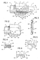
- the quick connection device 1 according to the invention and shown in Figures 1 and 2 is intended to be applied either on a rigid tube, for example steel, copper or aluminum, without prior preparation of the ends, or on a tube flexible or semi-rigid in synthetic material, in particular in polyamide.
- this quick connection device 1 comprises a body 2 provided, at one end 3, with a threaded end 4 and at the other end 5 with a hexagon 6.
- the latter serves, essentially, to screw the end piece threaded 4 into a threaded hole of a female connector not shown in the figures.
- Said body 2 further comprises a bore 7 opening, on the side of the threaded end piece 4, into an orifice 8, of diameter substantially equal to the internal diameter 9 of the pipe formed by the tube or pipe 10 at the end 11 from which the quick connection device 1 should be brought back.
- anchoring means 13 In this bore 7 of diameter greater than the diameter 12 of said tube or pipe 10 take place anchoring means 13, dilator means 14, cooperating with sealing means 15 and an upper retaining ring 16 ensuring the maintenance of these different elements.
- the quick connection device 1 comprises an inner bushing 17 comprising, on the one hand, a cylindrical end piece 18 on which the end 11 of the tube is threaded or pipe 10 and, on the other hand, a cylindrical seat 19 force fitted into the bore 7 of the body 2. More specifically, the end 20, oriented towards the threaded end 4 of this inner bush 17 abuts against the 'shoulder 21 located in the bore 7 and obtained due to the difference in the diameter of the latter and that of the orifice 8. As for the other end 22 of this inner sleeve 17, it is preferably , chamfered so as to facilitate the engagement of the cylindrical end piece 18 in the internal part 23 of the tube or pipe 10.
- the bore 7 has a recess 24 making it possible to define a shoulder 25 against which the anchoring means 13 mentioned above and shown in FIG. 3 bear.
- these are formed by a retaining washer 26 formed by an outer ring 27 of diameter adjusted to that of the bore 7, at the level of the recess 24, and the edge 28 of which cooperates with the shoulder 25.
- This outer ring 27 further comprises a plurality of elastic strips 29 substantially inclined towards the threaded end piece 4.
- the bore 7 has, at the step 24 and at a distance from the shoulder 25 slightly greater than the thickness of the retaining washer 26, a circular groove 30.
- an elastic ring 31, also called circlips cooperating with the edge 32 of this retaining washer 26 and keeping it in position in the bore 7 in the event of a force exerted on the tube or pipe 10 tending to extract the latter from the quick connection device 1.
- the internal diameter of this ring elastic or circlip 31 is substantially greater than the external diameter 12 of the tube or pipe 10 so as to define with the latter an annular space 33.
- the cylindrical surface 19 of the inner sleeve 17 has on its face 36 a recess circular 35 disposed in the extension of the cylindrical end piece 18. In this circular recess 35 is inserted the end of the tube or pipe 10 so as to remedy the aforementioned problem.
- dilator means 14 formed by a ring 37 adjusted to the diameter of the bore 7 at the recess 24.
- This ring 37 has a wedge shape at its edge 38 oriented towards the sealing means 15 and having the function of causing the radial expansion of the latter.
- the sealing means 15 are constituted, as shown in FIGS. 1 and 4, by a seal 39 provided on one side 40 with two circular lips 41, 42, cooperating, respectively, with the external periphery 43 of the tube or pipe 10 and the wall of the bore 7 at the level of the recess 24.
- These lips 41, 42 respect, between them, an angle allowing them to closely fit, the wedge shape of the edge 38 of the ring 37 forming the means dilators 14.
- the seal 39 this latter is constituted substantially by an O-ring 44 allowing to obtain an additional sealing zone between the bore 7 of the body 2 and the tube or pipe 10.
- FIGS. 1 and 5 Reference is made more particularly to FIGS. 1 and 5.
- the quick connection device 1 comprises means 45 capable of acting on the retaining washer 26 constituting the anchoring means 13 in order to annihilate their effects with respect to the tube or pipe 10 to, finally, authorize the withdrawal of the latter from the body 2.
- these means 45 are integral with the dilator means 14 and are formed by a cylindrical collar 46 with the dimensions defined by the annular space 33 delimited by the elastic ring 31 and the external periphery 43 of the tube or pipe 10.
- This cylindrical collar 46 is integral with the edge 66, oriented towards the threaded end 4, of the ring 37.
- said cylindrical flange 46 is caused to be introduced into the annular space 33 and to cooperate with the retaining washer 26 situated on the other side of the elastic ring 31.
- the cylindrical flange 46 cooperates with the elastic lamellae 29 and causes their erasure from the external periphery 43 of the tube or pipe 10.
- this cylindrical collar 46 has at its free end 60, a chamfer 61 facilitating its insertion between elastic strips 29 and the tube or pipe 10. It can also have a slightly three-fold shape. nconical contributing to its effectiveness.
- the length 47 of this cylindrical collar 46 is defined so that it does not exceed the free end 48 of the elastic strips 29, when the ring 37 abuts against the elastic ring 31. This characteristic makes it possible to bring said ring back 37 in its initial position after removing the tube or pipe 10 and, finally, releasing the elastic strips 29 in order to make the quick connection device reusable.
- this upper retaining ring 16 has a diameter slightly less than the bore 7 at the step 24 so as to slide on the latter.
- said upper retaining ring 16 has, on its outer periphery 62, a recess 50 defining a shoulder 67 intended to cooperate with a crimping 51 produced at the level of the body 2 at the outlet of the bore 7.
- this crimping 51 consists in maintaining, in the bore 7, essentially, the sealing means 15 and the upper retaining ring 16. It should, in fact, be noted, on the one hand, that the means of anchor 13 are immobilized by means of the elastic ring 31 and on the other hand, that the inner bush 17 is forcibly engaged in the bore 7. Furthermore, and according to a preferred embodiment, the inner bush 17 and, in particular, its cylindrical bearing surface 19 is provided with a peripheral rim 52 which is inserted into a circular groove 53 machined in the bore 7. This characteristic considerably improves the mechanical strength of the inner bushing 17 in the body 2.
- this tubular element 55 and, in particular, its internal diameter and the thickness of its wall 56 are determined as a function of the annular space 64 delimited by the crimping 51 and the external periphery 43 of the tube or pipe 10. Since said wall 56 necessarily has a reduced thickness 65, l tubular element 55 comprises at its free end 57 a reinforcement 58 formed by a bead or peripheral rim. On the latter can be applied the tool intended to push the upper retaining ring 16 into the bore 7. This pressure is, initially, passed on to the sealing means 15 causing the sliding of the dilator means in the bore 7 and , finally, the detachment of the anchoring means 13 from the tube or pipe 10.
Applications Claiming Priority (2)
| Application Number | Priority Date | Filing Date | Title |
|---|---|---|---|
| FR8803156A FR2628505B1 (fr) | 1988-03-08 | 1988-03-08 | Dispositif de raccordement rapide pour circuit hydraulique |
| FR8803156 | 1988-03-08 |
Publications (1)
| Publication Number | Publication Date |
|---|---|
| EP0336866A1 true EP0336866A1 (de) | 1989-10-11 |
Family
ID=9364162
Family Applications (1)
| Application Number | Title | Priority Date | Filing Date |
|---|---|---|---|
| EP89440020A Withdrawn EP0336866A1 (de) | 1988-03-08 | 1989-03-02 | Trennbare Rohrkupplung |
Country Status (4)
| Country | Link |
|---|---|
| EP (1) | EP0336866A1 (de) |
| DE (1) | DE336866T1 (de) |
| ES (1) | ES2012316A4 (de) |
| FR (1) | FR2628505B1 (de) |
Cited By (4)
| Publication number | Priority date | Publication date | Assignee | Title |
|---|---|---|---|---|
| EP0459713A2 (de) * | 1990-05-24 | 1991-12-04 | Shigeru Suzuki | Rohrverbinder |
| GB2304390A (en) * | 1995-08-15 | 1997-03-19 | Opella Ltd | Tube coupling with toothed retaining ring |
| FR2777341A1 (fr) * | 1998-04-08 | 1999-10-15 | Comap | Dispositif de raccordement instantane pour tuyau |
| WO2021042214A1 (en) * | 2019-09-05 | 2021-03-11 | 9352-4585 Québec Inc. | Plumbing fitting |
Citations (7)
| Publication number | Priority date | Publication date | Assignee | Title |
|---|---|---|---|---|
| DE1988017U (de) * | 1966-01-21 | 1968-06-20 | Pneumelec S A | Vorrichtung zum anschliessen eines rohres. |
| US4123090A (en) * | 1976-07-19 | 1978-10-31 | Imperial-Eastman Corporation | Push-pull fitting |
| GB2060106A (en) * | 1979-10-10 | 1981-04-29 | Britton Ltd C E & J P | Quick Release Tube Coupling |
| GB2160279A (en) * | 1984-06-13 | 1985-12-18 | Hawke Cable Glands Ltd | Releasable pipe coupling |
| FR2578306A1 (fr) * | 1985-01-03 | 1986-09-05 | Anoflex Flexibles | Raccord rapide pour circuits de fluide sous pression |
| FR2582771A2 (fr) * | 1985-05-31 | 1986-12-05 | Anoflex Flexibles | Raccord rapide pour circuits de fluide sous pression |
| FR2591309A1 (fr) * | 1985-12-11 | 1987-06-12 | Capri Codec Sa | Raccord hydraulique a branchement manuel rapide pour canalisation de fluide |
-
1988
- 1988-03-08 FR FR8803156A patent/FR2628505B1/fr not_active Expired - Lifetime
-
1989
- 1989-03-02 ES ES89440020T patent/ES2012316A4/es active Pending
- 1989-03-02 EP EP89440020A patent/EP0336866A1/de not_active Withdrawn
- 1989-03-02 DE DE1989440020 patent/DE336866T1/de active Pending
Patent Citations (7)
| Publication number | Priority date | Publication date | Assignee | Title |
|---|---|---|---|---|
| DE1988017U (de) * | 1966-01-21 | 1968-06-20 | Pneumelec S A | Vorrichtung zum anschliessen eines rohres. |
| US4123090A (en) * | 1976-07-19 | 1978-10-31 | Imperial-Eastman Corporation | Push-pull fitting |
| GB2060106A (en) * | 1979-10-10 | 1981-04-29 | Britton Ltd C E & J P | Quick Release Tube Coupling |
| GB2160279A (en) * | 1984-06-13 | 1985-12-18 | Hawke Cable Glands Ltd | Releasable pipe coupling |
| FR2578306A1 (fr) * | 1985-01-03 | 1986-09-05 | Anoflex Flexibles | Raccord rapide pour circuits de fluide sous pression |
| FR2582771A2 (fr) * | 1985-05-31 | 1986-12-05 | Anoflex Flexibles | Raccord rapide pour circuits de fluide sous pression |
| FR2591309A1 (fr) * | 1985-12-11 | 1987-06-12 | Capri Codec Sa | Raccord hydraulique a branchement manuel rapide pour canalisation de fluide |
Cited By (5)
| Publication number | Priority date | Publication date | Assignee | Title |
|---|---|---|---|---|
| EP0459713A2 (de) * | 1990-05-24 | 1991-12-04 | Shigeru Suzuki | Rohrverbinder |
| EP0459713A3 (en) * | 1990-05-24 | 1992-05-27 | Fujine Sangyo Company Limited | Pipe connector |
| GB2304390A (en) * | 1995-08-15 | 1997-03-19 | Opella Ltd | Tube coupling with toothed retaining ring |
| FR2777341A1 (fr) * | 1998-04-08 | 1999-10-15 | Comap | Dispositif de raccordement instantane pour tuyau |
| WO2021042214A1 (en) * | 2019-09-05 | 2021-03-11 | 9352-4585 Québec Inc. | Plumbing fitting |
Also Published As
| Publication number | Publication date |
|---|---|
| DE336866T1 (de) | 1990-05-03 |
| FR2628505A1 (fr) | 1989-09-15 |
| FR2628505B1 (fr) | 1990-05-18 |
| ES2012316A4 (es) | 1990-03-16 |
Similar Documents
| Publication | Publication Date | Title |
|---|---|---|
| EP2878873B1 (de) | Patronenartige schnellkupplungsvorrichtung | |
| FR2847646A1 (fr) | Raccord de tuyau | |
| CA2321137A1 (fr) | Dispositif de connexion d'une extremite de conduite a un organe | |
| EP0406145A1 (de) | Abdichtanordnung für verriegelte dichte Verbindungen | |
| FR2736988A1 (fr) | Raccord a tube | |
| EP2817548B1 (de) | Vorrichtung für abgedichtete kopplung ohne einen haltebereich | |
| FR2810087A1 (fr) | Element pourvu exterieurement de moyens pour cooperer avec un taraudage | |
| WO2004023013A2 (fr) | Moyens de connexion de conduits pour fluides haute pression | |
| FR2675234A1 (fr) | Manchon anticorrosion pour un percage pratique dans un tuyau en metal, et outil pour le montage de ce manchon. | |
| FR2591309A1 (fr) | Raccord hydraulique a branchement manuel rapide pour canalisation de fluide | |
| EP0336866A1 (de) | Trennbare Rohrkupplung | |
| EP2309164B1 (de) | Schnellkupplungsvorrichtung mit umgekehrtem Führungs- und Dichtungsbereich | |
| EP0187608B1 (de) | Schnellverbindung für unter Druck stehende Flüssigkeitssysteme in denen der Druck 150 bar erreichen kann | |
| FR2938038A1 (fr) | Element d'etancheite sans zone de retention et dispositif de raccordement comportant un tel element d'etancheite | |
| FR2578621A1 (fr) | Dispositif de raccordement amovible pour tuyaux | |
| WO2000050800A1 (fr) | Dispositif de connexion pour le raccordement d'une extremite de conduite a un organe | |
| EP3280942A1 (de) | Verbindungsvorrichtung mit beweglicher dichtung für abgeschrägtes rohr | |
| EP1522356A1 (de) | Abgedichtete Kupplungsvorrichtung für ein Rohr mit einem mit einem Gewinde versehenen Fortsatz | |
| FR2806779A1 (fr) | Procede d'assemblage d'un conduit sur un embout tubulaire rigide au moyen d'un ecrou visse sur l'embout, et raccord pour la mise en oeuvre du procede | |
| EP0046705A1 (de) | Verbindung zwischen einer Kunststoffleitung und einer metallischen Leitung für eine Flüssigkeit unter Druck | |
| FR2938625A1 (fr) | Dispositif de raccordement ayant des zones inversees d'etancheite et d'accrochage. | |
| FR2769350A1 (fr) | Procede et installation pour raccorder un tuyau souple et un embout tubulaire et dispositif de raccordement entre un tuyau souple et un embout tubulaire | |
| EP1139002A1 (de) | Verfahren zur Trennung eines Rohrendes von einer Kupplung und Anschlussvorrichtung hierfür | |
| EP0765991A1 (de) | Verfahren und Vorrichtung zur Verbindung von zwei Betonelementen | |
| FR2480900A3 (fr) | Tuyau souple a armature interne |
Legal Events
| Date | Code | Title | Description |
|---|---|---|---|
| PUAI | Public reference made under article 153(3) epc to a published international application that has entered the european phase |
Free format text: ORIGINAL CODE: 0009012 |
|
| AK | Designated contracting states |
Kind code of ref document: A1 Designated state(s): AT BE CH DE ES GB GR IT LI LU NL SE |
|
| 17P | Request for examination filed |
Effective date: 19891102 |
|
| ITCL | It: translation for ep claims filed |
Representative=s name: BUGNION S.P.A. |
|
| GBC | Gb: translation of claims filed (gb section 78(7)/1977) | ||
| TCAT | At: translation of patent claims filed | ||
| TCNL | Nl: translation of patent claims filed | ||
| DET | De: translation of patent claims | ||
| 17Q | First examination report despatched |
Effective date: 19910403 |
|
| STAA | Information on the status of an ep patent application or granted ep patent |
Free format text: STATUS: THE APPLICATION IS DEEMED TO BE WITHDRAWN |
|
| 18D | Application deemed to be withdrawn |
Effective date: 19910814 |