EP0336850B1 - Linearbeschleuniger mit selbstfokussierenden Kavitäten und hohen Elektronen-Einfangraten bei niedrigen Injektions-Vorbeschleunigungsspannungen - Google Patents
Linearbeschleuniger mit selbstfokussierenden Kavitäten und hohen Elektronen-Einfangraten bei niedrigen Injektions-Vorbeschleunigungsspannungen Download PDFInfo
- Publication number
- EP0336850B1 EP0336850B1 EP89400963A EP89400963A EP0336850B1 EP 0336850 B1 EP0336850 B1 EP 0336850B1 EP 89400963 A EP89400963 A EP 89400963A EP 89400963 A EP89400963 A EP 89400963A EP 0336850 B1 EP0336850 B1 EP 0336850B1
- Authority
- EP
- European Patent Office
- Prior art keywords
- cavity
- electrons
- field
- electric field
- cavities
- Prior art date
- Legal status (The legal status is an assumption and is not a legal conclusion. Google has not performed a legal analysis and makes no representation as to the accuracy of the status listed.)
- Expired - Lifetime
Links
- 238000002347 injection Methods 0.000 title claims description 9
- 239000007924 injection Substances 0.000 title claims description 9
- 230000005264 electron capture Effects 0.000 title 1
- 230000005684 electric field Effects 0.000 claims description 59
- 230000008878 coupling Effects 0.000 claims description 12
- 238000010168 coupling process Methods 0.000 claims description 12
- 238000005859 coupling reaction Methods 0.000 claims description 12
- 239000002245 particle Substances 0.000 claims description 12
- 230000008901 benefit Effects 0.000 claims description 3
- 230000000694 effects Effects 0.000 description 21
- 210000000554 iris Anatomy 0.000 description 5
- 230000001133 acceleration Effects 0.000 description 4
- 230000005672 electromagnetic field Effects 0.000 description 4
- 210000001331 nose Anatomy 0.000 description 4
- 238000005036 potential barrier Methods 0.000 description 4
- 230000007423 decrease Effects 0.000 description 3
- 238000009826 distribution Methods 0.000 description 3
- 230000004048 modification Effects 0.000 description 3
- 238000012986 modification Methods 0.000 description 3
- 230000010363 phase shift Effects 0.000 description 3
- 230000004888 barrier function Effects 0.000 description 2
- 238000000034 method Methods 0.000 description 2
- 230000010355 oscillation Effects 0.000 description 2
- 210000003323 beak Anatomy 0.000 description 1
- 230000001419 dependent effect Effects 0.000 description 1
- 238000010894 electron beam technology Methods 0.000 description 1
- 238000005516 engineering process Methods 0.000 description 1
- 230000002349 favourable effect Effects 0.000 description 1
- 230000035515 penetration Effects 0.000 description 1
- 230000009467 reduction Effects 0.000 description 1
- 239000000243 solution Substances 0.000 description 1
- 230000002123 temporal effect Effects 0.000 description 1
- 230000017105 transposition Effects 0.000 description 1
- 238000011144 upstream manufacturing Methods 0.000 description 1
Images
Classifications
-
- H—ELECTRICITY
- H05—ELECTRIC TECHNIQUES NOT OTHERWISE PROVIDED FOR
- H05H—PLASMA TECHNIQUE; PRODUCTION OF ACCELERATED ELECTRICALLY-CHARGED PARTICLES OR OF NEUTRONS; PRODUCTION OR ACCELERATION OF NEUTRAL MOLECULAR OR ATOMIC BEAMS
- H05H9/00—Linear accelerators
-
- H—ELECTRICITY
- H05—ELECTRIC TECHNIQUES NOT OTHERWISE PROVIDED FOR
- H05H—PLASMA TECHNIQUE; PRODUCTION OF ACCELERATED ELECTRICALLY-CHARGED PARTICLES OR OF NEUTRONS; PRODUCTION OR ACCELERATION OF NEUTRAL MOLECULAR OR ATOMIC BEAMS
- H05H7/00—Details of devices of the types covered by groups H05H9/00, H05H11/00, H05H13/00
- H05H7/14—Vacuum chambers
- H05H7/18—Cavities; Resonators
Definitions
- the present invention relates to a self-focusing cavity with a high electronic capture rate for moderate injection voltages. It finds more particularly its application in the field of linear accelerators, in particular of the type of those used in industrial control, or in the medical field, for which it contributes to improving reliability and efficiency of use.
- a linear accelerator essentially comprises a gun for injecting charged particles (most of the time electrons), to which is connected, downstream, an accelerating structure provided with a set of cavities aligned one behind the other.
- the cavities are supplied by a microwave power signal.
- the barrel for example in the case of electrons, conventionally comprises a cathode placed opposite a perforated anode. Under the effect of the electric field produced by the high voltage applied between the cathode and the anode, electrons are torn from the cathode. They gain speed before reaching the anode and escape from the barrel through the hole in the anode.
- the accelerating structure placed downstream of the barrel must then subject these electrons to several effects.
- the cavities are volumes in which microwave electromagnetic fields are such that an electric field prevails in the vicinity of axes of these cavities, axes which the electrons use when crossing these cavities. They are provided with an inlet hole to receive the injected particles and an opposite outlet hole to let them exit.
- the inlet and outlet holes conventionally have projections towards the interior of the cavity. These projections which surround these holes are called cavity noses.
- the walls of the cavities are of course metallic. The lines of the electric field in the vicinity of the holes cannot be in all points parallel to the axis of the cavity between its entry hole and its exit hole. Indeed these field lines are forced to close on the noses of cavities.
- this first cavity is lengthened while keeping the amplitudes and frequencies of the electric field identical, the phase of this electric field will reverse at the same time or before the packet of electrons has crossed the exit hole. Consequently, the electric field lines which result from this inversion after cancellation are then generally, at this instant, oriented towards the entrance to the cavity. This has the effect of slowing the package of electrons which is annoying. But this also has especially for effect, because of the radial component oriented in the right direction of this inverted electric field, a radial reconcentration of the emitted electrons. It is then necessary to adjust the increase in length of the first cavity so that the gain on focusing is not too penalizing on the loss of kinetic energy.
- L 1 k′ ⁇ ⁇ 0 .
- k ′ is a coefficient recommended as having to take the value 0.5; ß is the ratio of the average speed of the electrons to the speed of propagation of light and ⁇ 0 is the wavelength of the microwave wave created.
- the electric field at the entry of the first cavity no longer prevents the electrons from crossing it while the electric field at the exit of the first cavity presents itself as a barrier of potential to be crossed by electrons which would be in the course of their return towards the cathode (having for example been reflected at the entry of the second cavity with more intense field).
- the height of the barrier is determined on the one hand by the phase of the microwave wave in the first cavity at the moment when the retarded electrons cross the exit hole of this first cavity.
- This potential barrier is also intrinsically dependent on the amplitude of the microwave wave itself. It is therefore easy to see that by lowering the value of this amplitude, the height of this potential barrier is also lowered. It is this technical effect which was the subject of the aforementioned second patent application.
- V 0 is the energy of the electrons at the input of the first cavity (the numerical value V 0 , expressed in eV, is equal to that of the high injection voltage expressed in V), E 1 is l amplitude of the average electric field in this cavity, and T 1 is a factor of average transit angle representing the ratio between the energy actually acquired by the electrons and the energy which would be acquired by the latter if the synchronism between the field electric and electrons was respected at every point of the cavity.
- the combination of the two recommended solutions is in theory possible. It would consist in using a first cavity longer than a first normal cavity for synchronization, and in supplying this cavity so as to create a weaker electric field than that prevailing in the second cavity.
- the microwave electromagnetic energy stored in the first cavity is proportional to the square of the amplitude of the electric field and therefore decreases faster than the latter.
- the electrons of the first micro packets arriving in the low field cavity then pump all the electromagnetic energy stored, so that the electrons of the last micro packets are no longer subjected to any field in the first volume. And there the accelerator does not work.
- the object of the invention is to remedy these drawbacks by creating a self-focusing accelerating structure, that is to say using the self-focusing effect of the first cited patent application, and with a high rate of electronic capture, it that is to say using the technical effect of the second patent application cited, but for moderate injection voltages.
- the essential idea of the invention consists in playing on the shape of the first cavity so that the electric field in this cavity develops clearly asymmetrically with respect to the middle of this cavity. In a way, we optimize the shape of the field module after determining its extension along the axis and the amplitude of its maximum.
- this first cavity has a first part in which the field is weak followed downstream of a second part in which the field is strong.
- the electrons are moderately accelerated, they are especially gathered.
- the retarded electrons being subjected to generally more favorable field phases than the first arriving electrons catch up with these first electrons.
- the sufficiently grouped electrons are then accelerated over most of this second part of the first cavity. Then, when they are thus grouped together and accelerated, the electric field is canceled and finally reversed. Before they cross the exit hole of this first cavity, they are then slightly slowed down (which is a little unfavorable), but especially favorably autofocused by the radial component of the electric field inverted at the exit of the first cavity.
- the grouping occurs in the first part of the first cavity, the 100% capture is caused by the large accelerating field of the second part of the first cavity which is exerted on a grouping in progress, and the autofocusing is obtained by the absence of defocusing at the exit of the first cavity (and even a slight focusing) combined with the intense focusing obtained at the entry of the second cavity.
- these three effects occur in two successive coupled cavities.
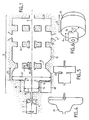
- FIG. 1 shows an accelerator device charged particles according to the invention.
- the charged particles here are essentially electrons produced by a gun 1 comprising an emissive cathode 2 and a hollow anode 3 provided with a hole 4 through which the emitted electrons can be injected into an arrangement 5 of accelerating cells located downstream.
- the arrangement 5 comprises, in the direction of injection, aligned along an axis 6 of acceleration, a certain number of accelerating microwave cavities.
- the cavities are located downstream of the barrel, they are subjected to a microwave electromagnetic field produced by a source not shown applied, for example, by a coupling 7 of the radial type in one of the cavities.
- the supply of microwave electromagnetic energy to the cavities can be done by coupling between the cavities by means of iris such as 8 and 9.
- this coupling can be magnetic.
- These irises are located for example respectively between a first cavity 10 and a second cavity 11, and between this second cavity 11 and a third cavity 12.
- the cavity 12 receives microwave energy.
- Other cavities such as 13 can also be placed downstream: their number and their function depend on the energy required for the particle beam accelerated out of the accelerator.
- the first cavity 10 is slightly longer than the normal length that it should have if we wanted all the electrons to cross it before the phase inversion of the microwave field prevailing in this cavity 10. Its length is for example of the same order as that mentioned in the first aforementioned patent application. It then occurs, at the exit of this first cavity, a refocusing of the electrons around the axis 6. Furthermore, the iris 8 is dimensioned in such a way that the amplitude of the microwave electric field which prevails in the cavity 10, even where it is strongest, is lower than the amplitude of the electric field which prevails in the cavity. 11. In practice, in accordance with what has been said previously, the ratio between these two fields is of the order of two. It is known by calculating the area of the section of the iris 8 to impose predetermined amplitude ratios.
- the first cavity essentially has means so that the module of the electric field in this first cavity is not symmetrical with respect to a mean plane 14 of this cavity.
- a mean plane 14 divides the cavity 10 longitudinally into two parts of substantially equal lengths.
- the cavity then comprises two parts, a first part on the left and a second part on the right of this mean plane.
- the left part 15 is smaller than the right part 16.
- the downstream part 16 when it is circular cylindrical, has a diameter 17 such that it allows the resonance of a TM O1 mode of the microwave electromagnetic field in this cavity.
- the left part 15 has a smaller diameter 18, for example half the diameter 17, so as to dampen this resonance.
- This part 15 constitutes a cut-off guide for the resonance mode established in the second part 16. Consequently the electric field in the first part 15 is less strong.
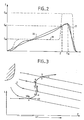
- FIG. 2 makes it possible to grasp the physical phenomenon implemented in the invention.
- This figure shows the amplitudes E of the electric fields developed in the first cavity 10 as a function of the abscissa of a point in this cavity measured according to the axis 6.
- the electric field has two plates for which the value of the amplitude is respectively E m and E M.
- the electrons injected by the barrel first meet the region 15 of the cavity 10 where the electric field has the value E m .
- This grouping is made easy by the very moderate energy of the incoming electrons. This goes in the same direction as the advantage sought for the invention consisting in using guns with low injection voltage.
- the average accelerating electric field developed in the second cavity is around 20 Mv / m, it is around 10 Mv / m in the second part of the first cavity, and it is around 5 Mv / m in the first part of the first cavity.
- the advantage of having a plateau of constant value E M with respect to a ramp 20 lies in the amplitude of the radial component of the electric field in a critical zone of abscissa Z c .
- This zone is a critical zone in the sense that it corresponds to the critical place of the cavity where some of the electrons have their minimum kinetic energy.
- the radial (defocusing) component of the field is proportional to the derivative, along the abscissa on axis 6, of the electric field. The less this electric field evolves (the flatter it is), the less it is defocusing.
- the modification of the shape of the cavity 1 to add the recess 15 to it can cause a modification of the resonant frequency of this cavity.
- This frequency is kept constant by slightly increasing the radius 17 compared to the value it would normally have if this cavity was of the conventional type.
- the inductance is thus increased by compensating for the reduction in capacitance linked to the addition of the recess formed by the part 15.
- FIG. 3 represents such a longitudinal oscillation. It represents the analysis of the movement of a critical electron (one of the first to arrive in the first part of the first cavity). The speeds have been broken down there, according to their longitudinal and radial components, at various points of the electronic trajectory.
- the electric field E has also been represented by taking account of its temporal evolution, first retarder and defocusing, then accelerator and focusing. The particle is stopped twice longitudinally, it has an unfavorable radial speed almost all the time, which causes a great distance from the axis. However, the addition of even a weak magnetic field causes the electrons to rotate azimuthly, which allows radial control.
- the constant longitudinal-oriented magnetic field can then be applied by any means known in the state of the art. In particular, a circular magnet 40, shown only partially in FIG. 1, can be added.
- FIG. 4 shows schematically in section alternative embodiments of the first cavity.
- the left part of the cavity is clearly a recess 22 made in a conventional cavity.
- the diameter of this conventional cavity must be slightly increased to obtain the same resonant frequency as that of the injected microwave wave.
- FIG. 5 the left part of the cavity 10, while having a smaller cross-sectional area than the right part (measured perpendicular to the axis 6), is even separated from the latter by a coupling hole 23. This hole this coupling must be carried out in such a way that it does not cause any phase shift between the waves maintained in the two parts of the cavity.
- FIG. 5 clearly shows a single cavity and not two coupled cavities like those described in the aforementioned patent applications.
- Figure 6 shows in perspective the preferred shape of the cavity shown in Figure 1.
- the upstream and downstream parts of this first cavity each have a length 24 and 25 substantially equal to each other.
- the radius 26 of the left part is less than half the radius 27 of the right part.
- the presence of a cavity nose 28 (FIG. 1) at the outlet of this first cavity has the effect, somewhat in the manner of a peak effect, of causing a concentration of the electric field lines directed on this nose. This also has a focusing effect overall.
- the first cavity 10 is connected to the second cavity 11 by a sliding space 29 the length of which is sufficient to delay the entry of the electron packet in relation to the evolution of the phase of the microwave signal in the second. cavity.
- the length of the sliding space 29 must ensure an accelerating amplitude at the entry of the second cavity greater than half the maximum amplitude. This means that the space 29 is worth substantially an eighth of a wavelength if all defocusing radial components have just been canceled when the beam leaves the first cavity. This value is quite reasonable and well suited to the thicknesses of iris and beaks practically used.
Landscapes
- Physics & Mathematics (AREA)
- Engineering & Computer Science (AREA)
- Plasma & Fusion (AREA)
- Spectroscopy & Molecular Physics (AREA)
- Particle Accelerators (AREA)
- Microwave Tubes (AREA)
Claims (6)
- Beschleunigungsapparat für geladene Teilchen- mit einer Kanone (1) zum Einführen der Teilchen,- einer Anordnung (5) mit vor der Kanone angeordneten Ultrahochfrequenz-Beschleunigungshohlräumen (10 bis 13), wobei die Anordnung in Richtung (6) der Einführung gesehen mindestens einen ersten (10) und dann einen zweiten (11) Hohlraum umfaßt, wobei die Länge (L1) des ersten Hohlraumes ausreicht, um jegliche Entfokussierung zu vermeiden oder sogar um ein Phänomen der Selbsfokussierung der Teilchen zu veranlassen, ehe diese den ersten Hohlraum verlassen,- und wobei der Apparat weiterhin Einrichtungen (8 und 9) umfaßt, die bewirken, daß das im ersten Hohlraum entwickelte elektrische Ultrahochfrequenzfeld geringer ist als das im zweiten Hohlraum entwickelte elektrische Ultrahochfrequenzfeld, dadurch gekennzeichnet, daß er- Einrichtungen (17 und 18) umfaßt, um im ersten Hohlraum eine in bezug auf eine mittlere Ebene (14) dieses ersten Hohlraumes unsymmetrischen profilierte Funktion des elektrischen Feldes einzurichten, wobei der Mittelwert (Em) des Feldes in einer ersten Partie (15) des ersten Hohlraums geringer ist als der Mittelwert (EM) des Feldes in einer zweiten nach dieser ersten Partie dieses ersten Hohlraumes gelegenen Partie (16).
- Apparat nach Anspruch 1, dadurch gekennzeichnet, daß die Länge der ersten Partie (15) größer ist als die Länge der zweiten Partie (16) des ersten Hohlraumes.
- Apparat nach Anspruch 1 oder nach Anspruch 2, dadurch gekennzeichnet, daß die Fläche (18) des Querschnittes des ersten Hohlraumes in der ersten Partie geringer ist als die Fläche (17) des Querschnittes des Hohlraumes in der zweiten Partie.
- Apparat nach einem der vorhergehenden Ansprüche 1 bis 8, dadurch gekennzeichnet, daß die erste Partie eine Schnittführung für einen Feldresonanzmodus in der zweiten Partie bildet.
- Apparat nach einem der vorhergehenden Ansprüche 1 bis 4, dadurch gekennzeichnet, daß die zwei Hohlräme (10 und 11) durch einen Gleitraum (8) voneineander getrennt sind, der länger ist als ein achtel der Wellenlänge, um in dem π-Koppelungsmodus eine Selbstfokussierung des Feldes am Eingang der zweiten Zelle zu begünstigen.
- Apparat nach einem der vorhergehenden Ansprüche 1 bis 5, dadurch gekennzeichnet, daß der erste Hohlraum (10) weiterhin mit magnetischen Fokussiereinrichtungen (40) versehen ist.
Applications Claiming Priority (2)
| Application Number | Priority Date | Filing Date | Title |
|---|---|---|---|
| FR8804707A FR2629976B1 (fr) | 1988-04-08 | 1988-04-08 | Accelerateur lineaire muni de cavites autofocalisantes a fort taux de capture electronique pour des tensions d'injections moderes |
| FR8804707 | 1988-04-08 |
Publications (2)
| Publication Number | Publication Date |
|---|---|
| EP0336850A1 EP0336850A1 (de) | 1989-10-11 |
| EP0336850B1 true EP0336850B1 (de) | 1992-09-23 |
Family
ID=9365142
Family Applications (1)
| Application Number | Title | Priority Date | Filing Date |
|---|---|---|---|
| EP89400963A Expired - Lifetime EP0336850B1 (de) | 1988-04-08 | 1989-04-07 | Linearbeschleuniger mit selbstfokussierenden Kavitäten und hohen Elektronen-Einfangraten bei niedrigen Injektions-Vorbeschleunigungsspannungen |
Country Status (5)
| Country | Link |
|---|---|
| US (1) | US4975652A (de) |
| EP (1) | EP0336850B1 (de) |
| JP (1) | JP2869084B2 (de) |
| DE (1) | DE68902944T2 (de) |
| FR (1) | FR2629976B1 (de) |
Families Citing this family (7)
| Publication number | Priority date | Publication date | Assignee | Title |
|---|---|---|---|---|
| FR2656192B1 (fr) * | 1989-12-14 | 1995-12-22 | Cgr Mev | Accelerateur lineaire pour grouper des particules chargees et les accelerer selon un faisceau fin et monoenergetique. |
| FR2679727B1 (fr) * | 1991-07-23 | 1997-01-03 | Cgr Mev | Accelerateur de protons a l'aide d'une onde progressive a couplage magnetique. |
| IT1281184B1 (it) * | 1994-09-19 | 1998-02-17 | Giorgio Trozzi Amministratore | Apparecchiatura per la radioterapia intraoperatoria mediante acceleratori lineari utilizzabili direttamente in sala operatoria |
| US6864633B2 (en) * | 2003-04-03 | 2005-03-08 | Varian Medical Systems, Inc. | X-ray source employing a compact electron beam accelerator |
| EP2214630A1 (de) | 2007-12-06 | 2010-08-11 | Unilever PLC | Körperpflegezusammensetzung |
| US12225656B2 (en) * | 2018-12-28 | 2025-02-11 | Shanghai United Imaging Healthcare Co., Ltd. | Accelerating apparatus for a radiation device |
| GB202016200D0 (en) | 2020-10-13 | 2020-11-25 | Res & Innovation Uk | Compact linac |
Family Cites Families (5)
| Publication number | Priority date | Publication date | Assignee | Title |
|---|---|---|---|---|
| FR2088883A5 (de) * | 1970-04-28 | 1972-01-07 | Thomson Csf | |
| FR2551617B1 (fr) | 1983-09-02 | 1985-10-18 | Cgr Mev | Structure acceleratrice lineaire autofocalisante de particules chargees |
| DE3483945D1 (en) * | 1983-09-30 | 1991-02-21 | Toshiba Kawasaki Kk | Gyrotron. |
| JPS61153924A (ja) * | 1984-12-26 | 1986-07-12 | Toshiba Corp | ジヤイロトロン装置 |
| FR2587164B1 (fr) * | 1985-09-10 | 1995-03-24 | Cgr Mev | Dispositif de pregroupement et d'acceleration d'electrons |
-
1988
- 1988-04-08 FR FR8804707A patent/FR2629976B1/fr not_active Expired - Fee Related
-
1989
- 1989-04-04 US US07/332,894 patent/US4975652A/en not_active Expired - Fee Related
- 1989-04-07 EP EP89400963A patent/EP0336850B1/de not_active Expired - Lifetime
- 1989-04-07 DE DE8989400963T patent/DE68902944T2/de not_active Expired - Fee Related
- 1989-04-10 JP JP1090500A patent/JP2869084B2/ja not_active Expired - Fee Related
Also Published As
| Publication number | Publication date |
|---|---|
| JP2869084B2 (ja) | 1999-03-10 |
| US4975652A (en) | 1990-12-04 |
| FR2629976A1 (fr) | 1989-10-13 |
| EP0336850A1 (de) | 1989-10-11 |
| DE68902944T2 (de) | 1993-03-11 |
| FR2629976B1 (fr) | 1991-01-18 |
| DE68902944D1 (de) | 1992-10-29 |
| JPH02148600A (ja) | 1990-06-07 |
Similar Documents
| Publication | Publication Date | Title |
|---|---|---|
| EP0359774B1 (de) | Elektronenbeschleuniger mit koaxialem hohlraum | |
| EP0013242B1 (de) | Generator für elektromagnetische Wellen sehr hoher Frequenz | |
| EP1095390B1 (de) | Mehrstrahlelektronenröhre mit magnetischem strahlenbahnkorrekturfeld | |
| EP2798209A1 (de) | Plasmatriebwerk und verfahren zur erzeugung eines plasmaantriebsschubs | |
| FR2643506A1 (fr) | Dispositif generateur d'ondes hyperfrequences a cathode virtuelle | |
| EP0407558B1 (de) | Mikrowellen-verstärker oder oszillator-anordnung | |
| EP0336850B1 (de) | Linearbeschleuniger mit selbstfokussierenden Kavitäten und hohen Elektronen-Einfangraten bei niedrigen Injektions-Vorbeschleunigungsspannungen | |
| BE1005864A5 (fr) | Accelerateur d'electrons a cavite resonante. | |
| EP0125167B1 (de) | Verstärkungsklystron hoher Leistung zur Speisung einer veränderlichen Last | |
| EP0526306B1 (de) | Wanderwellen-Protonbeschleuniger mit magnetischer Kupplung | |
| EP3216324B1 (de) | Laserplasmalinse | |
| EP0136216B1 (de) | Selbstfokussierende, lineare beschleunigende Struktur für geladene Teilchen | |
| FR2492158A1 (fr) | Tube a electrons pour gyrotron | |
| EP2936537B1 (de) | Mikrowellengenerator mit oszillierender virtueller kathode und offenen reflektoren | |
| EP0532411B1 (de) | Elektronzyklotronresonanz-Ionenquelle mit koaxialer Zuführung elektromagnetischer Wellen | |
| EP0124396B1 (de) | Elektronenstrahlinjektionsgerät für einen Mikrowellengenerator | |
| FR3134678A1 (fr) | Procédé et système d’accélération d’électrons par interaction laser-plasma | |
| EP0514255B1 (de) | Elektronzyklotronresonanz-Ionenquelle | |
| FR2598850A1 (fr) | Obturateur de plasma a flux axial | |
| FR2612726A1 (fr) | Dispositif accelerateur de particules comportant une cavite subharmonique | |
| FR2576477A1 (fr) | Ensemble accelerateur lineaire de particules chargees | |
| FR2587164A1 (fr) | Dispositif de pregroupement et d'acceleration d'electrons | |
| FR2476908A1 (fr) | Tube a ondes progressives pour tres hautes frequences et dispositif amplificateur utilisant un tel tube | |
| WO1992019087A1 (fr) | Procede pour reduire les instabilites des faisceaux de particules chargees groupees en paquets | |
| EP0482986A1 (de) | Kollektor für eine Mikrowellenröhre und Mikrowellenröhre mit einem solchen Kollektor |
Legal Events
| Date | Code | Title | Description |
|---|---|---|---|
| PUAI | Public reference made under article 153(3) epc to a published international application that has entered the european phase |
Free format text: ORIGINAL CODE: 0009012 |
|
| AK | Designated contracting states |
Kind code of ref document: A1 Designated state(s): CH DE GB LI NL SE |
|
| 17P | Request for examination filed |
Effective date: 19891114 |
|
| 17Q | First examination report despatched |
Effective date: 19911028 |
|
| GRAA | (expected) grant |
Free format text: ORIGINAL CODE: 0009210 |
|
| AK | Designated contracting states |
Kind code of ref document: B1 Designated state(s): CH DE GB LI NL SE |
|
| PG25 | Lapsed in a contracting state [announced via postgrant information from national office to epo] |
Ref country code: SE Effective date: 19920923 Ref country code: NL Effective date: 19920923 Ref country code: GB Effective date: 19920923 |
|
| REF | Corresponds to: |
Ref document number: 68902944 Country of ref document: DE Date of ref document: 19921029 |
|
| NLV1 | Nl: lapsed or annulled due to failure to fulfill the requirements of art. 29p and 29m of the patents act | ||
| GBV | Gb: ep patent (uk) treated as always having been void in accordance with gb section 77(7)/1977 [no translation filed] |
Effective date: 19920923 |
|
| PG25 | Lapsed in a contracting state [announced via postgrant information from national office to epo] |
Ref country code: LI Effective date: 19930430 Ref country code: CH Effective date: 19930430 |
|
| PLBE | No opposition filed within time limit |
Free format text: ORIGINAL CODE: 0009261 |
|
| STAA | Information on the status of an ep patent application or granted ep patent |
Free format text: STATUS: NO OPPOSITION FILED WITHIN TIME LIMIT |
|
| 26N | No opposition filed | ||
| REG | Reference to a national code |
Ref country code: CH Ref legal event code: PL |
|
| PGFP | Annual fee paid to national office [announced via postgrant information from national office to epo] |
Ref country code: DE Payment date: 20040601 Year of fee payment: 16 |
|
| PG25 | Lapsed in a contracting state [announced via postgrant information from national office to epo] |
Ref country code: DE Free format text: LAPSE BECAUSE OF NON-PAYMENT OF DUE FEES Effective date: 20051101 |