EP0336833A1 - Einstellbarer Anschlag - Google Patents
Einstellbarer Anschlag Download PDFInfo
- Publication number
- EP0336833A1 EP0336833A1 EP89400920A EP89400920A EP0336833A1 EP 0336833 A1 EP0336833 A1 EP 0336833A1 EP 89400920 A EP89400920 A EP 89400920A EP 89400920 A EP89400920 A EP 89400920A EP 0336833 A1 EP0336833 A1 EP 0336833A1
- Authority
- EP
- European Patent Office
- Prior art keywords
- cage
- stop
- locking
- sleeve
- inner tube
- Prior art date
- Legal status (The legal status is an assumption and is not a legal conclusion. Google has not performed a legal analysis and makes no representation as to the accuracy of the status listed.)
- Granted
Links
Images


Classifications
-
- E—FIXED CONSTRUCTIONS
- E05—LOCKS; KEYS; WINDOW OR DOOR FITTINGS; SAFES
- E05F—DEVICES FOR MOVING WINGS INTO OPEN OR CLOSED POSITION; CHECKS FOR WINGS; WING FITTINGS NOT OTHERWISE PROVIDED FOR, CONCERNED WITH THE FUNCTIONING OF THE WING
- E05F5/00—Braking devices, e.g. checks; Stops; Buffers
- E05F5/02—Braking devices, e.g. checks; Stops; Buffers specially for preventing the slamming of swinging wings during final closing movement, e.g. jamb stops
- E05F5/022—Braking devices, e.g. checks; Stops; Buffers specially for preventing the slamming of swinging wings during final closing movement, e.g. jamb stops specially adapted for vehicles, e.g. for hoods or trunks
-
- E—FIXED CONSTRUCTIONS
- E05—LOCKS; KEYS; WINDOW OR DOOR FITTINGS; SAFES
- E05F—DEVICES FOR MOVING WINGS INTO OPEN OR CLOSED POSITION; CHECKS FOR WINGS; WING FITTINGS NOT OTHERWISE PROVIDED FOR, CONCERNED WITH THE FUNCTIONING OF THE WING
- E05F5/00—Braking devices, e.g. checks; Stops; Buffers
- E05F5/06—Buffers or stops limiting opening of swinging wings, e.g. floor or wall stops
-
- E—FIXED CONSTRUCTIONS
- E05—LOCKS; KEYS; WINDOW OR DOOR FITTINGS; SAFES
- E05Y—INDEXING SCHEME ASSOCIATED WITH SUBCLASSES E05D AND E05F, RELATING TO CONSTRUCTION ELEMENTS, ELECTRIC CONTROL, POWER SUPPLY, POWER SIGNAL OR TRANSMISSION, USER INTERFACES, MOUNTING OR COUPLING, DETAILS, ACCESSORIES, AUXILIARY OPERATIONS NOT OTHERWISE PROVIDED FOR, APPLICATION THEREOF
- E05Y2900/00—Application of doors, windows, wings or fittings thereof
- E05Y2900/50—Application of doors, windows, wings or fittings thereof for vehicles
- E05Y2900/53—Type of wing
- E05Y2900/546—Tailboards, tailgates or sideboards opening upwards
Definitions
- the present invention relates to an adjustable stop, usable for example in an automobile, between the body and a hood or a trunk door.
- this stop that is to say the adjustment of the positioning of the hood or the trunk door relative to the body, is relatively long, even for experienced operators. A certain number of turns are indeed necessary, and it is very rare to rotate the stopper by the right amount at the first try, one or more adjustments are then necessary.
- the invention aims to provide a stop which can be adjusted more quickly.
- an adjustable stop which comprises: - a tubular bushing, an annular transverse end surface of which forms a stop surface; - A cage provided with holding means on a first element to which the stop must be fixed, comprising an outer tube and an inner coaxial tube of which, in cross section, for at least a portion respectively of the sleeve and the cage, the inner tube has an outer contour similar to the contour of the bushing bore and the outer tube a bore contour similar to the outer contour of the sleeve, said portion of the cage being designed to accommodate, between the outer tube and the inner tube, said portion of the sleeve; a locking rod intended to be placed in the bore of the inner tube of the cage, comprising with this inner tube means so that it admits a locking position there where it produces a radial force intended to be applied to the socket to block it in relation to the cage, and means so that it remains in this locking position; this stop being intended to be used in
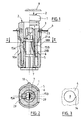
- the illustrated stop comprises according to the invention, a tubular sleeve 1, an annular transverse end surface 2 provides a stop surface; a cage 3 provided with holding means on a first element 4 - for example a vehicle body - on which the stop must be fixed, comprising an outer tube 5 and an inner tube 6 coaxial of which, in cross section, for at least one portion respectively of the sleeve and the cage, the inner tube has an outer contour similar to the contour of the bore of the sleeve and the outer tube a bore contour similar to the contour outside of the sleeve, said portion of the cage being designed to accommodate, between the outer tube and the inner tube, said portion of the sleeve; and a locking rod 7 intended to be disposed in the bore of the inner tube 6 of the cage, comprising with this inner tube means so that it admits a locking position where it produces a radial force intended to apply on the sleeve to block it relative to the cage, and means so that it remains in this
- This stop is intended to be used in a pre-assembled state shown in the right half-section of FIGS. 1 and 2, where said portion of the sleeve 1 is partially inserted between the outer tube 5 and the inner tube 6 of said portion of the cage in an initial position from which it can be inserted by sliding axially: the stop is put in place on said first element 4 on which it is then fixed thanks to said means for holding the cage, it is brought against the stop surface 2 of the socket a second element 8 - for example a cover or a trunk door - intended to come to carry therein and the first and the second elements are pushed against each other to adjust their relative positioning, which pushes the sleeve 1 into the cage 3, then the sleeve is locked in the cage by bringing the locking rod 7 to the locking position. The stop is then in the position shown in the left half-section of Figures 1 and 2, if one has been up to the maximum driving position.
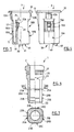
- the stop is intended to be mounted by simple insertion into a mounting orifice 9 of the first element 4 (see FIG. 3).
- the cage 3 comprises as holding means a flange 10 bordering the outer tube opposite the bottom 11 of the cage, intended to come to bear on the around the orifice 9; two diametrically opposite elastic retaining blades 12A and 12B, each movable through the side wall of the outer tube, spontaneously adopting a projecting position relative to this side wall, each blade being intended to come to bear on said wall of the first element 4 , opposite the face on which the flange 10 bears, as seen in FIG.
- an anti-rotation lug 13 (see Figures 2 and 4) disposed on the side wall of the outer tube, intended to engage in a corresponding groove 14 of the orifice 9.
- the lug prevents the rotation of the cage when rotates the locking rod to lock the socket in the cage.
- the means for the locking rod 7 to admit a locking position comprise: - for the inner tube 6 of the cage, two diametrically opposite elastic locking blades 15A and 15B, each movable through the side wall of the inner tube, spontaneously having an internal projection in the bore of the inner tube (see FIG. 5 and the right half-section of Figures 1 and 2); - For the locking rod 7, a cam 16 adapted to cooperate with said inner projection of each of the elastic blades 15A and 15B for, when bringing the rod to the locking position, move the elastic blade outwardly so that it has a projection outside the inner tube, intended to exert said radial force on the sleeve (see FIGS. 8, 9 and the left half-cut of FIGS. 1 and 2).
- the outer tube 5 has two diametrically opposite windows 18A and 18B opposite each of one of the locking blades 15A and 15B, in each of which is intended to engage a portion of the sleeve deformed by said outer projection of each elastic blade, as seen in the left half-section of Figures 1 and 2.
- sharp transverse teeth 17 have also been provided on the part of each locking blade projecting from the outside, intended to penetrate into the socket, to also improve the locking of the socket in the cage.
- the outer tube 5 is cylindrical, but has two flats 19A and 19B in which the window 18A and the window 18B are respectively provided; and on the socket 1 are provided corresponding diametrically opposite flats 20A and 20B.
- the socket 1 in order to facilitate its introduction into the cage as much as possible, also has two other diametrically opposite flats 20C and 20D equivalent to the flats 20A and 20B, which means that even in the most unfavorable initial angular positioning of the socket relative to the cage, it only takes a very small correction to reach an angular position where the socket can be engaged in the cage.
- Each flat part of the socket 1 has two transverse bosses 21A and 21B each intended to come against one of the transverse edges of the corresponding window (horizontal edges in the figures), in the preassembled state of the stop, as is seen on the right half-section of figure 1.
- the flats 20A and 20C of the sleeve extend from its end 22 by which it is pressed into the cage to a connection zone 23 whose location is provided to correspond to the insertion limit of the sleeve in the cage, in the initial position corresponding to the pre-assembled state of the stop (see the right half-section in Figure 1).
- the sleeve therefore sinks very easily into the cage as long as one remains below the connection zone 23, while beyond this there is a certain resistance due to the additional friction which then appears between the socket and cage.
- This measure therefore also promotes the convenience of locating the initial position of the sleeve in the cage during assembly of the stop: it suffices to push the sleeve until a blockage is felt to arrive at this initial position. It also makes it possible to do this assembly without forcing too much, while imposing to force when adjusting the stop.
- the cam 16 of the locking rod 7 is tapered and extends radially on either side of the axis of the rod (that is to say diametrically), this rod being designed to be brought by rotation to the locking position of the sleeve in the cage: in the pre-assembled state of the stop, the cam 16 is housed between the internal projections of the blades 15A and 15B without acting on these (see the right half-cuts of Figures 1 and 2), but when it is turned it pushes the blades outwards (see the left half-cuts of Figures 1 and 2).
- the means for the locking rod 7 to remain in the locking position comprise a locking notch 29 formed in each locking blade 15A and 15B (see FIGS. 2 and 5) in an axial direction, intended housing the end of the tapered cam 16 to immobilize the locking rod in rotation.
- the inner tube 6 is shorter than the outer tube 5 and has a cylindrical bore
- the locking rod comprises: a body 30 intended to be housed in the bore of the inner tube 6, comprising the tapered cam 16 and at least one surface for guiding the rod in rotation relative to the inner tube, here the ends of the ribs 31 and the cylindrical surfaces narrow 32 and 33 located on either side of the cam 16; - A transverse head 34 located at a first end of the body 30; at a second end thereof, distant from the first end by a distance similar to the length of the inner tube, two elastic blocking blades 35 and 36 each movable radially and spontaneously adopting a projecting position relative to the body 30 ; - A gripping zone 37 extending the rod 7 beyond this second end, having at the end an imprint 38 for a tool intended to rotate the locking rod, here for a flat blade screwdriver.
- This rod is rotatably mounted in the inner tube 6 by being introduced the gripping zone the first in the bore of the inner tube through the orifice 39 which has the inner surface 40 of the bottom of the cage, then by being pressed into this bore until the head 34 comes to bear against the outer surface 40 and that each locking blade 35 and 36 bears against the transverse end surface 25 of the inner tube.
- the operator when he has adjusted the positioning of elements 4 and 8, simply inserts the tool (here the screwdriver) into the bore of the sleeve 1 from above (as seen in the figure) to slide the tip of its tool into the cavity 38 and maneuver the locking rod, that is to say by making it perform a quarter turn.
- the socket is then locked in the position to which it was adjusted.
- the outer surface 40 of the bottom of the cage has a lug 41, and the head 34 two abutment surfaces 42 and 43 intended to limit the movement of the locking rod by coming into abutment against the lug 41, respectively when the rod blocking is in the angular waiting position and when it is in the locking position. It is thus certain that the operator, when he locks the stop, does not remain below or does not go beyond the position in which the end of the cam is engaged in the locking notch 29, and the we are in the same way sure of the initial position of the preassembled state.
- Figure 11 shows a variant 3A of the stop cage, where the blades 15A and 15B are replaced by comparable blades 44A and 44B diametrically opposed which are articulated in the upper part instead of being in the lower part, and which do not have no teeth 17.
- FIG. 12 illustrates a variant 1A of the tubular sleeve of the stop, which is no longer in one piece, but comprises a sleeve body 50 and a nut sleeve 51 cooperating coaxially with each other by a thread whose section is visible on the left half-section, and of which the primitive propeller 52 has been shown for the whole of the figure. It is the surface 2A of the nut 51 which in this variant carries the annular end surface which produces a stop surface.
- the body 50 and the nut 51 are in the maximum screwing configuration of the nut shown in the figure in the pre-assembled state of the stop.
- the socket 1A has been locked in the cage in the same way as the socket 1, an additional fine adjustment of the position of the stop surface is possible, by turning the nut 51 relative to the body 50 thanks to the maneuver footprint 53.
- the body 50 and the nut 51 are both made of flexible material, and the blocking of one with respect to the other is done by deformation of their thread.
- the cages 3 and 3 A are made of relatively hard material while the sockets 1 and 1A are made of flexible material.
- the socket 1 has on its side wall, near the stop surface 2, annular softening grooves 27 and 28 (see FIG. 6), which gives it a damper function between said first and second elements 4 and 8 for the shocks due to their meeting, but also for the vibrations.
- Such grooves can be envisaged if necessary on the nut 51 of the socket 1A.
Landscapes
- Mutual Connection Of Rods And Tubes (AREA)
- Snaps, Bayonet Connections, Set Pins, And Snap Rings (AREA)
- Braking Arrangements (AREA)
- Dowels (AREA)
Applications Claiming Priority (2)
| Application Number | Priority Date | Filing Date | Title |
|---|---|---|---|
| FR8804454 | 1988-04-05 | ||
| FR8804454A FR2629544B1 (fr) | 1988-04-05 | 1988-04-05 | Butee reglable |
Publications (2)
| Publication Number | Publication Date |
|---|---|
| EP0336833A1 true EP0336833A1 (de) | 1989-10-11 |
| EP0336833B1 EP0336833B1 (de) | 1993-03-17 |
Family
ID=9364950
Family Applications (1)
| Application Number | Title | Priority Date | Filing Date |
|---|---|---|---|
| EP89400920A Expired - Lifetime EP0336833B1 (de) | 1988-04-05 | 1989-04-04 | Einstellbarer Anschlag |
Country Status (6)
| Country | Link |
|---|---|
| US (1) | US4924549A (de) |
| EP (1) | EP0336833B1 (de) |
| JP (1) | JPH0276915A (de) |
| DE (1) | DE68905354T2 (de) |
| ES (1) | ES2038831T3 (de) |
| FR (1) | FR2629544B1 (de) |
Cited By (6)
| Publication number | Priority date | Publication date | Assignee | Title |
|---|---|---|---|---|
| EP0611868A1 (de) * | 1993-02-17 | 1994-08-24 | Emhart Inc. | Verstellbarer Anschlag |
| FR2705308A1 (fr) * | 1993-05-14 | 1994-11-25 | Renault | Butée réglable pour éléments mobiles de carrosserie d'automobile. |
| DE19514944C1 (de) * | 1995-04-22 | 1996-10-24 | Itw Ateco Gmbh | Selbstjustierender Dämfungsanschlag für bewegliche Teile |
| ES2122872A1 (es) * | 1995-05-23 | 1998-12-16 | Irausa Ing Sa | Eje-soporte clipsable para rueda o banda de rodadura. |
| EP0905344A3 (de) * | 1997-09-26 | 1999-09-15 | Arc Linea Arredamenti S.p.A. | Schliessdämpfer für Möbeltüren |
| WO2002008554A1 (de) * | 2000-07-20 | 2002-01-31 | Adam Opel Ag | Einstellbares dämpfungselement und verfahren zu dessen einstellung |
Families Citing this family (21)
| Publication number | Priority date | Publication date | Assignee | Title |
|---|---|---|---|---|
| ES2050560B1 (es) * | 1991-05-27 | 1994-12-01 | Cimas Jose Luis Ramirez | Limitador de giro para bisagras de eje. |
| US5482348A (en) * | 1993-07-12 | 1996-01-09 | Ford Motor Company | Vehicle hood support post member |
| DE29716111U1 (de) * | 1997-09-08 | 1997-11-13 | United Carr Gmbh Trw | Anschlagelement |
| US6088878A (en) * | 1998-05-22 | 2000-07-18 | Southco, Inc. | Height adjustable automotive deck lid bumper |
| US6119306A (en) | 1998-05-22 | 2000-09-19 | Southco, Inc. | Automotive deck lid bumper |
| IT1321053B1 (it) * | 2000-11-09 | 2003-12-30 | Fiat Auto Spa | Tampone di battuta regolabile per una parte mobile della carrozzeriadi un autoveicolo. |
| JP4085013B2 (ja) * | 2003-02-21 | 2008-04-30 | 日産自動車株式会社 | 緩衝装置 |
| US20050220569A1 (en) * | 2004-04-01 | 2005-10-06 | Joseph Dryer | Latching quick-connect connector |
| US7308731B2 (en) * | 2004-05-14 | 2007-12-18 | Newfrey Llc | Dampened slide for an anti-chucking wedge assembly |
| DE202004012733U1 (de) * | 2004-08-13 | 2004-10-21 | Böllhoff Verbindungstechnik GmbH | Einstelleinheit zum Einstellen des Abstandes zwischen zwei Bauteilen |
| DE102005006557A1 (de) * | 2005-02-11 | 2006-08-31 | Zf Friedrichshafen Ag | Anschlagpuffer für eine Tür oder Klappe eines Kraftfahrzeugs |
| DE102005011995A1 (de) * | 2005-03-16 | 2006-09-21 | General Motors Global Technology Operations, Inc., Detroit | Puffersystem für eine Fahrzeugklappe |
| FR2946383A1 (fr) * | 2009-06-09 | 2010-12-10 | Itw De France | Butee reglable. |
| US8919436B2 (en) | 2010-01-20 | 2014-12-30 | Guy Wheater | Wireline standoff |
| US9790748B2 (en) | 2013-07-24 | 2017-10-17 | Impact Selector International, Llc | Wireline roller standoff |
| FR3011869B1 (fr) * | 2013-10-14 | 2018-06-22 | A Raymond Et Cie | Dispositif de tampon a butee auto ajustable |
| US9523552B2 (en) * | 2015-05-04 | 2016-12-20 | Magpul Industries Corp. | Anti-rotational quick disconnect mount for a firearm |
| US9404708B1 (en) | 2015-06-30 | 2016-08-02 | Magpul Industries Corp. | Stock for a firearm |
| JP7115967B2 (ja) * | 2018-12-04 | 2022-08-09 | 株式会社パイオラックス | クッション装置 |
| JP7224311B2 (ja) * | 2020-02-04 | 2023-02-17 | 株式会社ニフコ | 緩衝装置 |
| US11946309B2 (en) * | 2020-08-17 | 2024-04-02 | Whirlpool Corporation | Adjustable bumper design for home appliances |
Citations (3)
| Publication number | Priority date | Publication date | Assignee | Title |
|---|---|---|---|---|
| DE835567C (de) * | 1950-09-30 | 1952-04-03 | Kiekert & Nieland | Stossdaempfer an Tuerzargen |
| FR2102516A5 (de) * | 1970-08-06 | 1972-04-07 | Profil Indle Financiere | |
| FR2565649A1 (fr) * | 1984-06-12 | 1985-12-13 | Renault | Butee reglable a ressort, notamment pour carrosseries d'automobiles |
Family Cites Families (6)
| Publication number | Priority date | Publication date | Assignee | Title |
|---|---|---|---|---|
| US1044412A (en) * | 1912-08-12 | 1912-11-12 | Albert S Newton | Door-buffer. |
| US1385448A (en) * | 1921-03-21 | 1921-07-26 | John H Harward | Door-buffer |
| US2929647A (en) * | 1957-10-14 | 1960-03-22 | Gladstone Hope | Door stop |
| US3766599A (en) * | 1971-07-30 | 1973-10-23 | Mullins Mf Co | Button hinge |
| US4218599A (en) * | 1977-11-30 | 1980-08-19 | Steelcase Inc. | Polymer spring |
| DE7914232U1 (de) * | 1979-05-17 | 1979-08-23 | Paul Hettich & Co, 4983 Kirchlengern | Mit einer glastuer versehener schrank |
-
1988
- 1988-04-05 FR FR8804454A patent/FR2629544B1/fr not_active Expired - Lifetime
-
1989
- 1989-04-04 DE DE8989400920T patent/DE68905354T2/de not_active Expired - Fee Related
- 1989-04-04 EP EP89400920A patent/EP0336833B1/de not_active Expired - Lifetime
- 1989-04-04 ES ES198989400920T patent/ES2038831T3/es not_active Expired - Lifetime
- 1989-04-05 JP JP1084933A patent/JPH0276915A/ja active Pending
- 1989-04-05 US US07/333,407 patent/US4924549A/en not_active Expired - Lifetime
Patent Citations (3)
| Publication number | Priority date | Publication date | Assignee | Title |
|---|---|---|---|---|
| DE835567C (de) * | 1950-09-30 | 1952-04-03 | Kiekert & Nieland | Stossdaempfer an Tuerzargen |
| FR2102516A5 (de) * | 1970-08-06 | 1972-04-07 | Profil Indle Financiere | |
| FR2565649A1 (fr) * | 1984-06-12 | 1985-12-13 | Renault | Butee reglable a ressort, notamment pour carrosseries d'automobiles |
Cited By (7)
| Publication number | Priority date | Publication date | Assignee | Title |
|---|---|---|---|---|
| EP0611868A1 (de) * | 1993-02-17 | 1994-08-24 | Emhart Inc. | Verstellbarer Anschlag |
| FR2705308A1 (fr) * | 1993-05-14 | 1994-11-25 | Renault | Butée réglable pour éléments mobiles de carrosserie d'automobile. |
| DE19514944C1 (de) * | 1995-04-22 | 1996-10-24 | Itw Ateco Gmbh | Selbstjustierender Dämfungsanschlag für bewegliche Teile |
| US5735511A (en) * | 1995-04-22 | 1998-04-07 | Itw-Ateco Gmbh | Self-adjusting stop means for cushioning |
| ES2122872A1 (es) * | 1995-05-23 | 1998-12-16 | Irausa Ing Sa | Eje-soporte clipsable para rueda o banda de rodadura. |
| EP0905344A3 (de) * | 1997-09-26 | 1999-09-15 | Arc Linea Arredamenti S.p.A. | Schliessdämpfer für Möbeltüren |
| WO2002008554A1 (de) * | 2000-07-20 | 2002-01-31 | Adam Opel Ag | Einstellbares dämpfungselement und verfahren zu dessen einstellung |
Also Published As
| Publication number | Publication date |
|---|---|
| US4924549A (en) | 1990-05-15 |
| ES2038831T3 (es) | 1993-08-01 |
| EP0336833B1 (de) | 1993-03-17 |
| DE68905354T2 (de) | 1993-06-24 |
| JPH0276915A (ja) | 1990-03-16 |
| FR2629544A1 (fr) | 1989-10-06 |
| DE68905354D1 (de) | 1993-04-22 |
| FR2629544B1 (fr) | 1991-01-04 |
Similar Documents
| Publication | Publication Date | Title |
|---|---|---|
| EP0336833B1 (de) | Einstellbarer Anschlag | |
| EP0148794B1 (de) | Winkelreguliereinrichtung eines getriebenen Drehelementes, an ein getriebenes Drehelement gekuppelt | |
| WO1996014526A1 (fr) | Embrayage de verrouillage pour dispositif d'accouplement hydrocinetique, notamment pour vehicules automobiles et son procede de montage | |
| EP0402198B1 (de) | Verriegelungsmutter | |
| FR3002574A1 (fr) | Butee a hauteur auto-reglable pour un ouvrant de vehicule automobile et procede pour regler une telle butee | |
| EP3684549A1 (de) | Befestigungssockel zur montage von strukturen und zugehörige befestigung | |
| EP0102898B1 (de) | Mutter mit automatischer positiver Sicherung | |
| FR2745235A1 (fr) | Accouplement en rotation d'une bride de roue a un organe de sortie d'un joint d'articulation d'une transmission | |
| FR2976987A1 (fr) | Dispositif de montage pour la fixation rotative et imperdable d'un element mecanique | |
| FR2611244A1 (fr) | Butee de debrayage a piece elastique a action axiale, notamment pour vehicule automobile | |
| EP0325069B1 (de) | Befestigungsmutter | |
| EP0491603B1 (de) | Verbindungsglied zwischen einem Scheibenwischerarm, insbesondere für Kraftfahrzeug | |
| EP3299650B1 (de) | Verfahren zum ausstatten eines endes eines dünnwandigen rohres mit einem mittels einer verschraubung einstellbaren axialanschlag | |
| EP3412523B1 (de) | Untereinheit eines steuerstands und steuerstand, die mithilfe eines blockierelements in einer transportstellung gehalten werden, sowie blockierverfahren dieses steuerstands mithilfe eines blockierelements | |
| EP0112766A1 (de) | Scheibenbremssattel mit entblockbarer Verstärkung | |
| EP0832369B1 (de) | Einstellbare kupplungsvorrichtung | |
| FR2796426A1 (fr) | Dispositif de fixation demontable a base de rondelle elastique | |
| FR2920104A1 (fr) | Mandrin porte-outil pour l'equipement d'une machine tournante | |
| EP2221494A1 (de) | Vorrichtung zur Fixierung eines Radiallagers einer Getriebewelle eines Kraftfahrzeuges | |
| EP2094986B1 (de) | Verbindungsvorrichtung zwischen einer ritzelwelle und einer lenksäulenkappe | |
| EP0300883A1 (de) | Schnellkupplung zwischen zwei ein Drehmoment übertragenden Elementen | |
| EP0831008A1 (de) | Befestigungssystem für ein Kraftfahrzeuglenkrad | |
| EP1104736B1 (de) | Vorrichtung zum Verbinden eines Lenkungsritzels mit einem Bügel | |
| FR2607201A1 (fr) | Dispositif de fixation sur fut filete ou annele | |
| EP1179469B1 (de) | Lenksäule für ein Kraftfahrzeuglenksystem |
Legal Events
| Date | Code | Title | Description |
|---|---|---|---|
| PUAI | Public reference made under article 153(3) epc to a published international application that has entered the european phase |
Free format text: ORIGINAL CODE: 0009012 |
|
| AK | Designated contracting states |
Kind code of ref document: A1 Designated state(s): DE ES IT |
|
| 17P | Request for examination filed |
Effective date: 19891123 |
|
| 17Q | First examination report despatched |
Effective date: 19910211 |
|
| GRAA | (expected) grant |
Free format text: ORIGINAL CODE: 0009210 |
|
| AK | Designated contracting states |
Kind code of ref document: B1 Designated state(s): DE ES IT |
|
| REF | Corresponds to: |
Ref document number: 68905354 Country of ref document: DE Date of ref document: 19930422 |
|
| ITF | It: translation for a ep patent filed | ||
| REG | Reference to a national code |
Ref country code: ES Ref legal event code: FG2A Ref document number: 2038831 Country of ref document: ES Kind code of ref document: T3 |
|
| PLBE | No opposition filed within time limit |
Free format text: ORIGINAL CODE: 0009261 |
|
| STAA | Information on the status of an ep patent application or granted ep patent |
Free format text: STATUS: NO OPPOSITION FILED WITHIN TIME LIMIT |
|
| 26N | No opposition filed | ||
| PGFP | Annual fee paid to national office [announced via postgrant information from national office to epo] |
Ref country code: DE Payment date: 20070423 Year of fee payment: 19 |
|
| PGFP | Annual fee paid to national office [announced via postgrant information from national office to epo] |
Ref country code: ES Payment date: 20070427 Year of fee payment: 19 |
|
| PGFP | Annual fee paid to national office [announced via postgrant information from national office to epo] |
Ref country code: IT Payment date: 20070626 Year of fee payment: 19 |
|
| PG25 | Lapsed in a contracting state [announced via postgrant information from national office to epo] |
Ref country code: DE Free format text: LAPSE BECAUSE OF NON-PAYMENT OF DUE FEES Effective date: 20081101 |
|
| REG | Reference to a national code |
Ref country code: ES Ref legal event code: FD2A Effective date: 20080405 |
|
| PG25 | Lapsed in a contracting state [announced via postgrant information from national office to epo] |
Ref country code: ES Free format text: LAPSE BECAUSE OF NON-PAYMENT OF DUE FEES Effective date: 20080405 |
|
| PG25 | Lapsed in a contracting state [announced via postgrant information from national office to epo] |
Ref country code: IT Free format text: LAPSE BECAUSE OF NON-PAYMENT OF DUE FEES Effective date: 20080404 |