EP0336624B1 - Daten-Wiedergabegerät - Google Patents
Daten-Wiedergabegerät Download PDFInfo
- Publication number
- EP0336624B1 EP0336624B1 EP89302998A EP89302998A EP0336624B1 EP 0336624 B1 EP0336624 B1 EP 0336624B1 EP 89302998 A EP89302998 A EP 89302998A EP 89302998 A EP89302998 A EP 89302998A EP 0336624 B1 EP0336624 B1 EP 0336624B1
- Authority
- EP
- European Patent Office
- Prior art keywords
- data
- synchronous
- digital signals
- signals
- bit rate
- Prior art date
- Legal status (The legal status is an assumption and is not a legal conclusion. Google has not performed a legal analysis and makes no representation as to the accuracy of the status listed.)
- Expired - Lifetime
Links
- 230000001360 synchronised effect Effects 0.000 claims description 73
- 230000005236 sound signal Effects 0.000 claims description 36
- 230000001172 regenerating effect Effects 0.000 claims description 2
- 238000010586 diagram Methods 0.000 description 9
- 230000006870 function Effects 0.000 description 5
- 238000000034 method Methods 0.000 description 5
- 230000003111 delayed effect Effects 0.000 description 2
- 238000001514 detection method Methods 0.000 description 2
- 230000010354 integration Effects 0.000 description 2
- 238000006243 chemical reaction Methods 0.000 description 1
- 230000000295 complement effect Effects 0.000 description 1
- 125000004122 cyclic group Chemical group 0.000 description 1
- 230000001419 dependent effect Effects 0.000 description 1
- 238000004519 manufacturing process Methods 0.000 description 1
- 229910044991 metal oxide Inorganic materials 0.000 description 1
- 150000004706 metal oxides Chemical class 0.000 description 1
- 239000004065 semiconductor Substances 0.000 description 1
Images




Classifications
-
- G—PHYSICS
- G11—INFORMATION STORAGE
- G11B—INFORMATION STORAGE BASED ON RELATIVE MOVEMENT BETWEEN RECORD CARRIER AND TRANSDUCER
- G11B5/00—Recording by magnetisation or demagnetisation of a record carrier; Reproducing by magnetic means; Record carriers therefor
- G11B5/008—Recording on, or reproducing or erasing from, magnetic tapes, sheets, e.g. cards, or wires
- G11B5/00813—Recording on, or reproducing or erasing from, magnetic tapes, sheets, e.g. cards, or wires magnetic tapes
- G11B5/00847—Recording on, or reproducing or erasing from, magnetic tapes, sheets, e.g. cards, or wires magnetic tapes on transverse tracks
- G11B5/0086—Recording on, or reproducing or erasing from, magnetic tapes, sheets, e.g. cards, or wires magnetic tapes on transverse tracks using cyclically driven heads providing segmented tracks
-
- G—PHYSICS
- G11—INFORMATION STORAGE
- G11B—INFORMATION STORAGE BASED ON RELATIVE MOVEMENT BETWEEN RECORD CARRIER AND TRANSDUCER
- G11B20/00—Signal processing not specific to the method of recording or reproducing; Circuits therefor
- G11B20/00007—Time or data compression or expansion
-
- G—PHYSICS
- G11—INFORMATION STORAGE
- G11B—INFORMATION STORAGE BASED ON RELATIVE MOVEMENT BETWEEN RECORD CARRIER AND TRANSDUCER
- G11B20/00—Signal processing not specific to the method of recording or reproducing; Circuits therefor
- G11B20/10—Digital recording or reproducing
-
- G—PHYSICS
- G11—INFORMATION STORAGE
- G11B—INFORMATION STORAGE BASED ON RELATIVE MOVEMENT BETWEEN RECORD CARRIER AND TRANSDUCER
- G11B27/00—Editing; Indexing; Addressing; Timing or synchronising; Monitoring; Measuring tape travel
- G11B27/02—Editing, e.g. varying the order of information signals recorded on, or reproduced from, record carriers
- G11B27/031—Electronic editing of digitised analogue information signals, e.g. audio or video signals
- G11B27/032—Electronic editing of digitised analogue information signals, e.g. audio or video signals on tapes
-
- G—PHYSICS
- G11—INFORMATION STORAGE
- G11B—INFORMATION STORAGE BASED ON RELATIVE MOVEMENT BETWEEN RECORD CARRIER AND TRANSDUCER
- G11B27/00—Editing; Indexing; Addressing; Timing or synchronising; Monitoring; Measuring tape travel
- G11B27/36—Monitoring, i.e. supervising the progress of recording or reproducing
-
- H—ELECTRICITY
- H04—ELECTRIC COMMUNICATION TECHNIQUE
- H04N—PICTORIAL COMMUNICATION, e.g. TELEVISION
- H04N5/00—Details of television systems
- H04N5/76—Television signal recording
- H04N5/78—Television signal recording using magnetic recording
- H04N5/782—Television signal recording using magnetic recording on tape
- H04N5/7824—Television signal recording using magnetic recording on tape with rotating magnetic heads
- H04N5/7826—Television signal recording using magnetic recording on tape with rotating magnetic heads involving helical scanning of the magnetic tape
- H04N5/78263—Television signal recording using magnetic recording on tape with rotating magnetic heads involving helical scanning of the magnetic tape for recording on tracks inclined relative to the direction of movement of the tape
- H04N5/78266—Television signal recording using magnetic recording on tape with rotating magnetic heads involving helical scanning of the magnetic tape for recording on tracks inclined relative to the direction of movement of the tape using more than one track for the recording of one television field or frame, i.e. segmented recording
-
- H—ELECTRICITY
- H04—ELECTRIC COMMUNICATION TECHNIQUE
- H04N—PICTORIAL COMMUNICATION, e.g. TELEVISION
- H04N5/00—Details of television systems
- H04N5/76—Television signal recording
- H04N5/91—Television signal processing therefor
- H04N5/92—Transformation of the television signal for recording, e.g. modulation, frequency changing; Inverse transformation for playback
- H04N5/928—Transformation of the television signal for recording, e.g. modulation, frequency changing; Inverse transformation for playback the sound signal being pulse code modulated and recorded in time division multiplex with the modulated video signal
-
- H—ELECTRICITY
- H04—ELECTRIC COMMUNICATION TECHNIQUE
- H04N—PICTORIAL COMMUNICATION, e.g. TELEVISION
- H04N9/00—Details of colour television systems
- H04N9/79—Processing of colour television signals in connection with recording
- H04N9/80—Transformation of the television signal for recording, e.g. modulation, frequency changing; Inverse transformation for playback
- H04N9/81—Transformation of the television signal for recording, e.g. modulation, frequency changing; Inverse transformation for playback the individual colour picture signal components being recorded sequentially only
-
- H—ELECTRICITY
- H04—ELECTRIC COMMUNICATION TECHNIQUE
- H04N—PICTORIAL COMMUNICATION, e.g. TELEVISION
- H04N9/00—Details of colour television systems
- H04N9/79—Processing of colour television signals in connection with recording
- H04N9/80—Transformation of the television signal for recording, e.g. modulation, frequency changing; Inverse transformation for playback
- H04N9/82—Transformation of the television signal for recording, e.g. modulation, frequency changing; Inverse transformation for playback the individual colour picture signal components being recorded simultaneously only
- H04N9/8205—Transformation of the television signal for recording, e.g. modulation, frequency changing; Inverse transformation for playback the individual colour picture signal components being recorded simultaneously only involving the multiplexing of an additional signal and the colour video signal
- H04N9/8233—Transformation of the television signal for recording, e.g. modulation, frequency changing; Inverse transformation for playback the individual colour picture signal components being recorded simultaneously only involving the multiplexing of an additional signal and the colour video signal the additional signal being a character code signal
-
- G—PHYSICS
- G11—INFORMATION STORAGE
- G11B—INFORMATION STORAGE BASED ON RELATIVE MOVEMENT BETWEEN RECORD CARRIER AND TRANSDUCER
- G11B2220/00—Record carriers by type
- G11B2220/90—Tape-like record carriers
Definitions
- the invention relates to apparatus for generating digital signals corresponding to data recorded on a recording medium.
- the invention relates to magnetic reproducing apparatus for reproducing video signals and audio signals from data on inclined tracks of a recorded medium with a rotary magnetic head.
- Rotary head type VCRs operate to record and reproduce video signals and audio signals to/from tracks on magnetic tape.
- An example of a typical tape format is shown in Figure 2 of the accompanying drawings.
- Video tracks 34 for recording video signals and audio tracks 35 for recording digital audio signals form inclined tracks 33 on a magnetic tape 30 which normally travels in the direction of its length as indicated by an arrow 31.
- a rotary magnetic head scans tracks 33 in the direction indicated by an arrow 32.
- TCI Time Compressed Integration
- PCM Pulse Code Modulation
- digital audio signals are recorded as digital audio signals on the audio tracks 35.
- original input analog audio signals are first digitalized (PCM).
- PCM signals are process interleaved and error correction words are inserted.
- the resulting signals are modulated and synchronous words are inserted.
- the audio signals are recorded on the audio track 35 of the magnetic tape 30.
- Figure 9 of the accompanying drawings shows a block diagram of a conventional reproducing apparatus for reproducing digital audio signals.
- Signals on the audio tracks are sensed by a magnetic head 1 and are supplied to an amplifier 3 through a rotary transformer 2.
- the frequency characteristics of the amplified signals are compensated by an equalizer 4, and the reproduced signals are detected by a decision circuit 5 responsive to a bit clock signal f1 supplied from a clock regenerator 7.
- This bit clock signal f1 is generated using the output signal of the equalizer 4 and a gate signal 10 of a servo circuit 9.
- the reproduced audio signals are input to a synchronous circuit 22.
- the synchronous circuit 22 detects the inserted synchronous words recorded on the audio tracks and cancels undesired synchronous words which are generated by bit errors.
- the digital audio signals are separated into the synchronous words, audio data and bit clock signals.
- the magnetic head (recording head, reproducing head) becomes worn.
- this reduces the interchangeability with other VCR apparatus because it causes equalizing errors.
- the bit clock signal f1 regenerated by the clock regenerator 7 experiences time base errors called "jitter" which cause errors or problems in the operation of the apparatus.
- the synchronous circuit 22 driven by a high frequency (48.6 MHz), such as an ECL (Emitter-Coupled Logic) device, is used.
- a high frequency 48.6 MHz
- ECL Electrode-Coupled Logic
- an ECL device dissipates a large amount of power when the bit rate of the digital audio signals is more than about 50 Mbps (bit per second).
- CMOS Complementary Metal-Oxide Semiconductor
- data reproducing apparatus for generating digital signals corresponding to data recorded on a recording medium, the data including synchronous words for establishing synchronization, each synchronous word corresponding to a predetermined arrangement of a portion of the data
- the data reproducing apparatus comprising: detecting means for detecting the recorded data from the medium and for generating digital data signals, corresponding to the recorded data and including the synchronous words, having a first predetermined bit rate; including expansion means for converting the digital data signals, including the synchronous words, from the detecting means into expanded digital signals and for providing the expanded digital signals, including the synchronous words, with a second bit rate lower than the first bit rate; and synchronous detector means coupled to the expansion means for receiving said expanded digital signals with said second bit rate (f2) and extracting the portions of the expanded digital signals corresponding to the synchronous words.
- data reproducing apparatus for generating digital signals corresponding to data recorded on a recording medium, the data including synchronous words for establishing synchronization, each synchronous word corresponding to a predetermined arrangement of a portion of the data
- the data reproducing apparatus comprising means for generating serial digital signals including the synchronous words corresponding to the recorded data on the medium and having a first predetermined bit rate; and converter means for converting the serial digital signals to parallel digital signals including the synchronous words; including means for temporarily storing the parallel data responding to the parallel digital signals at a first speed; means for reading the stored parallel data and for regenerating the parallel digital signals at a second speed less than the first speed; means for reconverting the regenerated parallel digital signals to serial digital signals including the synchronous words and thereby having a second bit rate lower than the first bit rate; and synchronous detector means coupled to the reconverting means for receiving said digital signals with said second bit rate and extracting the portions of the serial digital signals corresponding to the synchronous words.
- time base expansion is employed. This expression refers to converting reproduced data of high bit rate to reproduced data of low bit rate.
- the time base expansion circuit converts the high bit rate (e.g. 48.6 MHz) of reproduced data to a lower bit rate (e.g. 12.15 MHz) before supplying it to the synchronous detector.
- the skew of the reproduced data signal can be reduced, and the jitter of bit clock signal f1 can be restrained by control of the phase relation between the reproduced data signal and bit clock signal f1.
- a synchronous detector having a lower speed, as compared with the bit rate of the recorded digital signal, can be used.
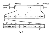
- Fig. 3 shows a format of PCM audio signals 50 on one audio track. This one audio track 51 is divided into 45 blocks (#0 - #45). Each block includes a synchronous signal (SYNC) 52, a address signal 53, a cyclic redundancy check character signal (CRCC) 54, blocked data (D0, ..., D23) 55 and two error correct signals (C1, C2).
- SYNC synchronous signal
- CRCC cyclic redundancy check character signal
- C1, C2 two error correct signals
- Fig. 4 One segment (number), as shown in Fig. 4, is made of two tracks and a PCM audio signal of one track is as shown above in Fig. 3. Namely, the numeral 50 in Fig. 4(b) corresponds to the PCM audio signal shown in Fig. 3.
- Original audio signals (IN-A) are sampled at 48.6MHz and encoded by PCM. Then the audio signals are divided into individual field units. Moreover, the divided audio signals are divided in to three segment. Each block of a segment includes, as described above, a synchronous signal, an address signal, a CRCC signal, block data and error correct words recorded on the tape.
- the original audio signal (IN-A) corresponding to the video signal F1 at the time during scanning of segments number 1, 2, 3, is delayed by one frame period and recorded at the time of segment numbers 6, 7, and 8.
- Video signals (VIDEO 60) as shown in Fig. 3, is processed with TCI (Time Compressed Integration), shuffling in one field and conversion of one field to three segments.
- the components of the input video signal are R (red), G (Green), B (blue) or Y (luminance) signals, C w , C n (chrominance signals), etc.
- These video signals are, for example, the signals shown in Fig. 6, which is a TCI waveform.
- This waveform includes a synchronous signal (SYNC.), a burst signal, a segment index signal, a chrominance signal (C w or C n ), a Y signal, etc.
- F1 INPUT One field's video signals (F1 INPUT) which are input during scanning segment numbers 1, 2, 3, as shown in Fig. 4(a), are delayed one frame and recorded on the tracks correspond to segment numbers 7, 8, 9 on the tape. At almost the same time, the signals are reproduced and monitored (PB out ).
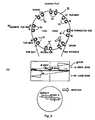
- Fig. 5(a) shows a cross sectional plan view of the magnetic heads
- Fig. 5(b) shows a cross sectional side view.
- the rotary head drum includes an upper drum 86 and a lower drum 87.
- the upper drum 86 accommodates a pair of Record and Play (reproduce) heads A1B1 82, A2B2 82′, Play-back heads A1 ⁇ B1 ⁇ 83, A2 ⁇ B2 ⁇ 83′, Erase heads e11e12 85, e21e22 85′ and Advanced Play-back heads (to reproduce in front of Erase heads) A1′B1′ 84, A2′B2′ 84′.
- Another pair of heads which has the same function is arranged at the opposite position.
- the Record and Play head has a function to record and reproduce video signals and audio signals.
- the Play-back head has a function to monitor the recording condition.
- the Advanced Play-back head is used in the editing mode and has a function to reproduce signals from a magnetic tape in advance of the Erase head. Also each of a pair of heads 88, 89, which scan a track of one segment, for example Play-back head A1 ⁇ B2 ⁇ , is shifted 0.023 mm radially away from the center of the rotary head drum, as shown Fig. 5(b).
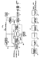
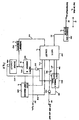
- the digital audio signals are reproduced by the reproducing system according to the preferred embodiment of the invention, as shown in Fig. 1.
- the reproduced digital audio signals are detected by a data detector 101.
- the detected audio signal are time base expanded by a time base expander 102.
- the synchronous signal of the audio signal (PCM) is detected by a synchronous detector 103 and decoded by a decoder 104.
- the audio signal is processed for error correction as usual in prior art and is time base compensated by an error corrector 105.
- the resulting signal is converted to an analog signal by a digital to analog converter 106.
- Fig. 1(b) is a block diagram which explains Fig. 1(a) in more detail.
- the audio signals on the magnetic tape which is reproduced by rotary magnetic head (A, B) 1
- Output signals from the amplifier 3 are input to an equalizer 4 and any difference of frequency characteristic between the recorded and reproduced signals is compensated.
- Output signals from the equalizer 4 are digitalized, and arranged in a waveform, and the first reproduced data 6 is generated by the decision circuit 5.
- Output signals from equalizer 4 are also input to a clock regenerator 7, and a first bit clock signal f1 8 is generated.
- a servo circuit 9 generates a first audio gate signal, which shows the period that the digital audio signal is existing.
- the clock regenerator 7 generates the first bit clock signal f1 corresponding to the output signal from the equalizer 4 within the period of the first audio gate signal.
- This first bit clock signal f1 is supplied to the decision circuit 5 and used to arrange the waveform.
- the above described circuits correspond to the data detector (101 in Fig. 1(a)).
- the first reproduced data 6 from the decision circuit 5 is input to a time base expander 100.
- This circuit includes a serial to parallel converter 11, a memory 14 and a parallel to serial converter 19.
- This serial to parallel converter 11 is, for instance, as shown in Fig. 7, constructed by an n step shift register 300 and an n bit latch circuit 301, which latches the parallel output signal, an ECL to TTL (Transistor Transistor Logic) converter 302 and a 1/N frequency-divider 308.
- ECL to TTL Transistor Transistor Logic
- first bit clock signal 8 of frequency f1 (f2 ⁇ f1) supplied from the clock regenerator 7 and converted the first reproduced data 6 (serial data) to first parallel data 12 by n parallel bits, where each bit has an f1/N (bps; bit per second) bit rate.
- serial to parallel converter 11 simultaneously generates the first clock signal 13 of frequency f1/N.
- a fast shift register operated at f1 is needed, but the circuit scale of this is smaller than that of a synchronous detector 22 (described hereinafter).
- the memory 14 is input with the first parallel data 12 and the first clock signal 13 from the serial to parallel converter 11.
- This memory 14 is, for example, as shown in Fig. 7, constructed by FIFO (First-In First-Out) Memory 303, a memory controller 304 and a 1/N frequency divider 305, and memorizes the first parallel data 12 by FIFO's control signal (address) from the memory controller 304.
- This is determined by the first clock signal f1/N 13 and the first audio gate signal 10 during the period of the first audio gate signal 10. Namely, the memory 14, having a comparatively low access speed, can be used.
- the second bit clock (f2) generated by a clock generator 15 is supplied to the memory 14.
- a second parallel data 17 from FIFO 303 (of the memory 14) is read out during a period when the data 12 is not memorized into the FIFO 303.
- An address for reading out from FIFO 303 changes corresponding to the speed of f2/N 18, which the second bit clock f2 is divided into 1/N frequency by a 1/N frequency-divider 305. It is output the second clock 18, so f2/N from the 1/N frequency-divider 305 of memory 14.
- the second parallel data 17 and the second clock f2/N 18 are supplied to the parallel to serial converter 19.
- This circuit for example, as shown in Fig. 7, includes an n step shift register 306.
- This shift register 306 generates a second reproduced data 20 which has bit rate of f2 (bps) and a third bit clock (f2) 21 by the input timing of the second bit clock (f2) 16.
- the second reproduced data 20 and the second bit clock 21 are input to the synchronous detector 22.
- the second reproduced gate signal 24 from the second gate signal generator 23 corresponds to the existing period of the digital audio signals to the second reproduced data 20.
- the signals 24 is referred to the first gate signal.
- the synchronous detector 22 has an operation that cancels "unexpected by synchronous word" caused by bit error, detects the real synchronous words inserted during the recording mode and outputs the predetermined synchronous word, audio data and bit clock at each of tree terminals 25, 26, 27. Namely, the bit rate for the time base expansion can be determined from the period which the magnetic head is reproducing the video signal by controlling the second bit clock f2 from the clock generator 15.
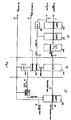
- This circuit includes a synchronous word detector 200, a logic circuit 201, a counter A 202, B 205, a window generator 207, a decode circuit 206, a shift register 208, and a gate circuit 203, 204.
- the synchronous word detector 200 has a function of detecting synchronous words, and a window for detecting synchronous words is generated by window generator 207.
- the counter B 205 generates an address at an input reset timing.
- Decode circuit 206 decodes the address and the shift register 208 generates a reset pulse.
- the logic circuit 201 is reset a predetermined amount by the counter A 202.
- a logic circuit 201 is reset by input of timing signal 209 from a gate circuit 204, and this signal 209 is generated by the input of second audio gate signal 24. Simultaneously a counter A 202 is reset by a reset signal 210 from the logic circuit 201. This condition is called "S0".
- a synchronous word detector 200 detects the synchronous word included in the second reproduced data 20.
- the counter B 205 is not reset and the shift register 208 is not cleared.
- the counter A 202 is not reset and the counter A 202 is counted-up by signal 215 input in EN2 (enable). Then, when the counted-up value of the counter A 202 is less than a predetermined value, it is still on the condition of "S2".
- the logic circuit 201 is reset by signal 209 via the gate 204 from counter A 202 and the counter A 202 is reset by signal 210 from the logic circuit 201. Namely, it is returned to the condition of "S0".
- the above described circuits correspond to the synchronous detector 22 is Fig. 1.
- the bit rate of the second reproduced data 20 which is input to the synchronous detector 22 is f2 (bps), is lower than the bit rate f1 (bps) of the first reproduced data 6. Namely, if f2 is selected to be under about 12.15MHz, for example, a CMOS IC is used as a synchronous detector 22. It is most important to predetermine a rate of expansion such as to maintain the time to correct errors.
- the digital audio signals are recorded on a part of the tracks and the video signals are recorded on an other part of the tracks.
- the period when the rotary magnetic head is reproducing the video signals can be obtained in addition to moving between the tracks to reproduce the digital audio signals.
- the rate of time base expansion can be determined considering this period (dependent on the format of magnetic tape) and a process time for error correction.
- the second audio gate signals which show the existing period of the second reproduced data 20 may be generated from the read out address of the memory 14.
- a RAM Random Access Memory
Landscapes
- Engineering & Computer Science (AREA)
- Signal Processing (AREA)
- Multimedia (AREA)
- Signal Processing For Digital Recording And Reproducing (AREA)
- Television Signal Processing For Recording (AREA)
Claims (5)
- Daten-Wiedergabevorrichtung zum Erzeugen digitaler Signale, die auf einem Aufzeichnungsmedium (30) aufgezeichneten Daten entsprechen, wobei die Daten Synchronwörter zum Einrichten von Synchronisation aufweisen, wobei jedes Synchronwort einer vorbestimmten Anordnung eines Teils der Daten entspricht, wobei die Daten-Wiedergabevorrichtung aufweist: eine Nachweiseinrichtung (101) zum Erfassen der aufgezeichneten Daten von dem Medium (30) und zum Erzeugen von digitalen Datensignalen, die den aufgezeichneten Daten entsprechen und die Synchronwörter aufweisen, mit einer ersten vorbestimmten Bitrate (f₁); eine Expansionseinrichtung (102) zum Konvertieren der digitalen Datensignale, einschließlich der Synchronwörter, von der Nachweiseinrichtung (101) in expandierte digitale Signale und zum Bereitstellen der expandierten digitalen Signale, einschließlich der Synchronwörter, mit einer zweiten Bitrate (f₂), die niedriger ist als die erste Bitrate (f₁); und eine Synchrondetektoreinrichtung (103), die mit der Expansionseinrichtung (102) zum Empfangen der expandierten digitalen Signale mit der zweiten Bitrate (f₂) und zum Extrahieren der Teile der expandierten digitalen Signale, die den Synchronwörtern entsprechen, gekoppelt ist.
- Vorrichtung nach Anspruch 1, wobei die Daten auch Audiodaten und Fehlerkorrekturwörter aufweisen und die digitalen Signale Audiosignale aufweisen, und wobei die Vorrichtung auch eine Fehlerkorrektureinrichtung (105) zum Modifizieren der Audiosignale in Antwort auf die Fehlerkorrekturwörter aufweist.
- Daten-Wiedergabevorrichtung zum Erzeugen digitaler Signale, die auf einem Aufzeichnungsmedium (30) aufgezeichneten Daten entsprechen, wobei die Daten Synchronwörter zum Einrichten von Synchronisation aufweisen, wobei jedes Synchronwort einer vorbestimmten Anordnung eines Teils der Daten entspricht, wobei die Daten-Wiedergabevorrichtung eine Einrichtung (4, 5) zum Erzeugen serieller digitaler Signale einschließlich der Synchronwörter, die den auf dem Medium (30) aufgezeichneten Daten entsprechen und eine erste vorbestimmte Bitrate (f₁) haben; und eine Konvertereinrichtung (11) zum Konvertieren der seriellen digitalen Signale in parallele digitale Signale einschließlich der Synchronwörter aufweist; mit einer Einrichtung (14) zum zeitweiligen Speichern der parallelen Daten, die auf die parallelen digitalen Signale mit einer ersten Geschwindigkeit (f₁/N) anspricht; einer Einrichtung (14) zum Lesen der gespeicherten parallelen Daten und zum Regenerieren der parallelen digitalen Signale mit einer zweiten Geschwindigkeit (f₂/N), die geringer ist als die erste Geschwindigkeit (f₁/N); einer Einrichtung (19) zum Rekonvertieren der regenerierten parallelen digitalen Signale in serielle digitale Signale einschließlich der Synchronwörter, dabei mit einer zweiten Bitrate (f₂), die niedriger ist als die erste Bitrate; und einer Synchrondetektoreinrichtung (103), die mit der Rekonvertiereinrichtung (19) gekoppelt ist, zum Empfangen der digitalen Signale mit der zweiten Bitrate (f₂) und zum Extrahieren der Teile der seriellen digitalen Signale entsprechend den Synchronwörtern.
- Vorrichtung nach Anspruch 3, wobei die Konvertiereinrichtung (11) ein n-stufiges Schieberegister und eine n-Bit-Verriegelungsschaltung aufweist.
- Vorrichtung nach Anspruch 3 oder 4, wobei die Rekonvertiereinrichtung (19) ein n-stufiges Schieberegister aufweist.
Applications Claiming Priority (2)
| Application Number | Priority Date | Filing Date | Title |
|---|---|---|---|
| JP63073797A JPH01245470A (ja) | 1988-03-28 | 1988-03-28 | 回転ヘッド型磁気記録再生装置 |
| JP73797/88 | 1988-03-28 |
Publications (3)
| Publication Number | Publication Date |
|---|---|
| EP0336624A2 EP0336624A2 (de) | 1989-10-11 |
| EP0336624A3 EP0336624A3 (de) | 1991-05-15 |
| EP0336624B1 true EP0336624B1 (de) | 1995-06-28 |
Family
ID=13528526
Family Applications (1)
| Application Number | Title | Priority Date | Filing Date |
|---|---|---|---|
| EP89302998A Expired - Lifetime EP0336624B1 (de) | 1988-03-28 | 1989-03-28 | Daten-Wiedergabegerät |
Country Status (5)
| Country | Link |
|---|---|
| US (1) | US5101394A (de) |
| EP (1) | EP0336624B1 (de) |
| JP (1) | JPH01245470A (de) |
| KR (1) | KR920008146B1 (de) |
| DE (1) | DE68923210T2 (de) |
Families Citing this family (4)
| Publication number | Priority date | Publication date | Assignee | Title |
|---|---|---|---|---|
| JP2833852B2 (ja) * | 1990-10-26 | 1998-12-09 | 山形日本電気株式会社 | ディジタル信号出力回路 |
| US5404362A (en) * | 1991-12-04 | 1995-04-04 | Meitner; Edmund | Very low jitter clock recovery from serial audio data |
| KR100244745B1 (ko) * | 1996-06-29 | 2000-02-15 | 김영환 | 싱크 워드 검출회로 |
| GB0400662D0 (en) * | 2004-01-13 | 2004-02-11 | Koninkl Philips Electronics Nv | Method and apparatus for control of a write signal in an optical disc system |
Citations (1)
| Publication number | Priority date | Publication date | Assignee | Title |
|---|---|---|---|---|
| JPS6316471A (ja) * | 1986-07-08 | 1988-01-23 | Matsushita Electric Ind Co Ltd | デイジタルデ−タの再生装置 |
Family Cites Families (12)
| Publication number | Priority date | Publication date | Assignee | Title |
|---|---|---|---|---|
| JPS5435893B2 (de) * | 1974-11-09 | 1979-11-06 | ||
| US4091418A (en) * | 1977-03-02 | 1978-05-23 | Zenith Radio Corporation | Automatic channel equalization with time base expansion |
| JPS5593513A (en) * | 1978-12-28 | 1980-07-16 | Sony Corp | Recording device of pulse train signal |
| JPS5665309A (en) * | 1979-10-26 | 1981-06-03 | Sony Corp | Time-axis converter |
| JPS5773577A (en) * | 1980-10-27 | 1982-05-08 | Sony Corp | Control signal fetch circuit |
| GB2089178B (en) * | 1980-11-18 | 1984-07-04 | Sony Corp | Digital signal processing |
| US4413288A (en) * | 1981-12-07 | 1983-11-01 | Rca Corporation | Indicator control signal generator for video tape recorder |
| JPS58188921A (ja) * | 1982-04-28 | 1983-11-04 | Canon Inc | 時間軸変換装置 |
| JPS58200654A (ja) * | 1982-05-18 | 1983-11-22 | Nec Corp | 通信装置 |
| DE3225365A1 (de) * | 1982-07-07 | 1984-01-12 | Robert Bosch Gmbh, 7000 Stuttgart | Verfahren zur wandlung serieller datensignale |
| EP0117276B1 (de) * | 1982-09-20 | 1990-05-09 | Sanyo Electric Co., Ltd. | Gerät zur Geheimübertragung |
| US4780769A (en) * | 1985-02-05 | 1988-10-25 | Sony Corporation | Recording and reproducing apparatus for time compressed video signals wherein said signals are expanded and converted into two separate channels before recording |
-
1988
- 1988-03-28 JP JP63073797A patent/JPH01245470A/ja active Pending
-
1989
- 1989-03-28 EP EP89302998A patent/EP0336624B1/de not_active Expired - Lifetime
- 1989-03-28 DE DE68923210T patent/DE68923210T2/de not_active Expired - Lifetime
- 1989-03-28 US US07/329,673 patent/US5101394A/en not_active Expired - Lifetime
- 1989-03-28 KR KR1019890003884A patent/KR920008146B1/ko not_active Expired
Patent Citations (1)
| Publication number | Priority date | Publication date | Assignee | Title |
|---|---|---|---|---|
| JPS6316471A (ja) * | 1986-07-08 | 1988-01-23 | Matsushita Electric Ind Co Ltd | デイジタルデ−タの再生装置 |
Also Published As
| Publication number | Publication date |
|---|---|
| KR890015242A (ko) | 1989-10-28 |
| US5101394A (en) | 1992-03-31 |
| DE68923210T2 (de) | 1996-01-25 |
| EP0336624A2 (de) | 1989-10-11 |
| EP0336624A3 (de) | 1991-05-15 |
| DE68923210D1 (de) | 1995-08-03 |
| JPH01245470A (ja) | 1989-09-29 |
| KR920008146B1 (ko) | 1992-09-22 |
Similar Documents
| Publication | Publication Date | Title |
|---|---|---|
| EP0367217B1 (de) | Verfahren zur Aufzeichnung und Wiedergabe von Informationssignalen und Gerät dafür | |
| CA1209695A (en) | Recording and/or reproducing apparatus | |
| AU629522B2 (en) | Circuit for detecting a synchronizing signal | |
| US5682457A (en) | Method and apparatus for recording HDTV signals having a wide bandwidth on a narrow bandwidth tape | |
| KR910009464B1 (ko) | 디지탈 신호 재생장치 | |
| US5101394A (en) | Data reproducing apparatus | |
| US5438459A (en) | Method of processing and recording data while reproducing the same and apparatus for the method | |
| US5463505A (en) | Helical-scan information recording-playback apparatus | |
| US6134384A (en) | Digital signal recording/reproducing apparatus and recording method | |
| US4870647A (en) | Digital signal demodulator | |
| US5815331A (en) | Digital signal recording method and apparatus involving precode processing for partial response detection | |
| EP0159111B1 (de) | Verfahren und Gerät zum Speichern/Auslesen digitaler Daten auf/von einem Videoband | |
| JP3321884B2 (ja) | 同期ブロック検出方法および同期ブロック検出装置 | |
| JP2580432B2 (ja) | 同期方法 | |
| JP3598838B2 (ja) | データ読み取り装置 | |
| JP3271073B2 (ja) | 磁気再生装置 | |
| JP2736448B2 (ja) | フレーム同期回路 | |
| JP2615684B2 (ja) | ディジタル信号再生装置 | |
| JP2586775B2 (ja) | ディジタル信号記録再生装置 | |
| JPH0729257A (ja) | 回転ヘッド式デジタル記録/再生方法及び装置 | |
| JPH03187070A (ja) | デジタル信号処理回路 | |
| JPH04355273A (ja) | ディジタルデータの記録再生装置 | |
| JPH06195875A (ja) | 再生装置 | |
| JPS63177373A (ja) | デイジタルvtrの信号処理方式 | |
| JP2001155395A (ja) | ディジタル信号再生方法および再生装置 |
Legal Events
| Date | Code | Title | Description |
|---|---|---|---|
| PUAI | Public reference made under article 153(3) epc to a published international application that has entered the european phase |
Free format text: ORIGINAL CODE: 0009012 |
|
| 17P | Request for examination filed |
Effective date: 19890410 |
|
| AK | Designated contracting states |
Kind code of ref document: A2 Designated state(s): DE FR GB NL |
|
| PUAL | Search report despatched |
Free format text: ORIGINAL CODE: 0009013 |
|
| AK | Designated contracting states |
Kind code of ref document: A3 Designated state(s): DE FR GB NL |
|
| 17Q | First examination report despatched |
Effective date: 19930927 |
|
| GRAA | (expected) grant |
Free format text: ORIGINAL CODE: 0009210 |
|
| AK | Designated contracting states |
Kind code of ref document: B1 Designated state(s): DE FR GB NL |
|
| ET | Fr: translation filed | ||
| REF | Corresponds to: |
Ref document number: 68923210 Country of ref document: DE Date of ref document: 19950803 |
|
| PLBE | No opposition filed within time limit |
Free format text: ORIGINAL CODE: 0009261 |
|
| STAA | Information on the status of an ep patent application or granted ep patent |
Free format text: STATUS: NO OPPOSITION FILED WITHIN TIME LIMIT |
|
| 26N | No opposition filed | ||
| REG | Reference to a national code |
Ref country code: GB Ref legal event code: 746 Effective date: 19981008 |
|
| REG | Reference to a national code |
Ref country code: FR Ref legal event code: D6 |
|
| PGFP | Annual fee paid to national office [announced via postgrant information from national office to epo] |
Ref country code: NL Payment date: 19990329 Year of fee payment: 11 |
|
| PG25 | Lapsed in a contracting state [announced via postgrant information from national office to epo] |
Ref country code: NL Free format text: LAPSE BECAUSE OF NON-PAYMENT OF DUE FEES Effective date: 20001001 |
|
| NLV4 | Nl: lapsed or anulled due to non-payment of the annual fee |
Effective date: 20001001 |
|
| PGFP | Annual fee paid to national office [announced via postgrant information from national office to epo] |
Ref country code: FR Payment date: 20010313 Year of fee payment: 13 |
|
| REG | Reference to a national code |
Ref country code: GB Ref legal event code: IF02 |
|
| PG25 | Lapsed in a contracting state [announced via postgrant information from national office to epo] |
Ref country code: FR Free format text: LAPSE BECAUSE OF NON-PAYMENT OF DUE FEES Effective date: 20021129 |
|
| REG | Reference to a national code |
Ref country code: FR Ref legal event code: ST |
|
| PGFP | Annual fee paid to national office [announced via postgrant information from national office to epo] |
Ref country code: DE Payment date: 20080407 Year of fee payment: 20 |
|
| PGFP | Annual fee paid to national office [announced via postgrant information from national office to epo] |
Ref country code: GB Payment date: 20080402 Year of fee payment: 20 |
|
| REG | Reference to a national code |
Ref country code: GB Ref legal event code: PE20 Expiry date: 20090327 |
|
| PG25 | Lapsed in a contracting state [announced via postgrant information from national office to epo] |
Ref country code: GB Free format text: LAPSE BECAUSE OF EXPIRATION OF PROTECTION Effective date: 20090327 |