EP0335839B1 - Mechanische Vorrichtung zur Selbsteinstellung des Endanschlagschiebers beim Anheben von motorisierten Läden - Google Patents
Mechanische Vorrichtung zur Selbsteinstellung des Endanschlagschiebers beim Anheben von motorisierten Läden Download PDFInfo
- Publication number
- EP0335839B1 EP0335839B1 EP89830060A EP89830060A EP0335839B1 EP 0335839 B1 EP0335839 B1 EP 0335839B1 EP 89830060 A EP89830060 A EP 89830060A EP 89830060 A EP89830060 A EP 89830060A EP 0335839 B1 EP0335839 B1 EP 0335839B1
- Authority
- EP
- European Patent Office
- Prior art keywords
- drums
- gear
- drum
- shutter
- motor
- Prior art date
- Legal status (The legal status is an assumption and is not a legal conclusion. Google has not performed a legal analysis and makes no representation as to the accuracy of the status listed.)
- Expired - Lifetime
Links
- 230000008878 coupling Effects 0.000 claims abstract description 13
- 238000010168 coupling process Methods 0.000 claims abstract description 13
- 238000005859 coupling reaction Methods 0.000 claims abstract description 13
- 230000000284 resting effect Effects 0.000 claims description 8
- 230000033001 locomotion Effects 0.000 abstract description 11
- 230000005540 biological transmission Effects 0.000 description 5
- 230000000694 effects Effects 0.000 description 1
- 238000009434 installation Methods 0.000 description 1
- 239000002699 waste material Substances 0.000 description 1
Images


Classifications
-
- E—FIXED CONSTRUCTIONS
- E06—DOORS, WINDOWS, SHUTTERS, OR ROLLER BLINDS IN GENERAL; LADDERS
- E06B—FIXED OR MOVABLE CLOSURES FOR OPENINGS IN BUILDINGS, VEHICLES, FENCES OR LIKE ENCLOSURES IN GENERAL, e.g. DOORS, WINDOWS, BLINDS, GATES
- E06B9/00—Screening or protective devices for wall or similar openings, with or without operating or securing mechanisms; Closures of similar construction
- E06B9/56—Operating, guiding or securing devices or arrangements for roll-type closures; Spring drums; Tape drums; Counterweighting arrangements therefor
- E06B9/80—Safety measures against dropping or unauthorised opening; Braking or immobilising devices; Devices for limiting unrolling
- E06B9/82—Safety measures against dropping or unauthorised opening; Braking or immobilising devices; Devices for limiting unrolling automatic
- E06B9/88—Safety measures against dropping or unauthorised opening; Braking or immobilising devices; Devices for limiting unrolling automatic for limiting unrolling
-
- E—FIXED CONSTRUCTIONS
- E06—DOORS, WINDOWS, SHUTTERS, OR ROLLER BLINDS IN GENERAL; LADDERS
- E06B—FIXED OR MOVABLE CLOSURES FOR OPENINGS IN BUILDINGS, VEHICLES, FENCES OR LIKE ENCLOSURES IN GENERAL, e.g. DOORS, WINDOWS, BLINDS, GATES
- E06B9/00—Screening or protective devices for wall or similar openings, with or without operating or securing mechanisms; Closures of similar construction
- E06B9/56—Operating, guiding or securing devices or arrangements for roll-type closures; Spring drums; Tape drums; Counterweighting arrangements therefor
- E06B9/68—Operating devices or mechanisms, e.g. with electric drive
- E06B2009/6809—Control
- E06B2009/6872—Control using counters to determine shutter position
- E06B2009/6881—Mechanical counters
Definitions
- This patent application for an industrial invention concerns a mechanical device for the self-recording of the end of stroke slider, when motorised shutters are being raised, with the result that it is no longer necessary to set said slider, which stops the geared motor at the end of the upward stroke of the shutter; currently the slider is set by means of various trial and error attempts on the part of the installer which is a considerable waste of time.
- These regulation registers are actually composed of two opposite limit microswitches, the position of which is adjustable and against which there beats a slider screwed along a threaded rod, made to rotate, first in one direction and then in the opposite direction, by the same geared motor which activates the shutter.
- the limit microswitches are fixed and they are struck by two adjustable screws which protrude from opposite sides of the aforementioned slider.
- the aim of the instant invention is to eliminate this setting phase by trial and error, having designed a mechanical device, thanks to which, it is possible to obtain self-recording of the end of stroke slider which stops the geared motor, when the shutter has reached its top dead centre.
- the device is based on the use, for each of the two end of stroke sliders, of a coupling joint, composed of a gear-motor, which can turn idle around the threaded rod, to which each slider is helically coupled and of a drum integral to the aforementioned threaded rod, which is constantly subjected to the returning action of a prestressed spring, which tends to push the drum against said gear,and coupling between them results in the transmission of motion from the first to the second following the coupling of their respective teeth.
- a diaphragm positioned between the gear and the drum can stop the latter, integral to the threaded rod, from translating under the thrust of the returning spring, towards the gear-motor carrying out the coupling through which the transmission of motion is effected, from the gear to the drum and from here to the threaded rod, on which consequently the slider starts to traslate.
- Said diaphragm has a large central opening which can only be axially crossed by the drum, when the two radial lobes protruding from the latter on diametrically opposite sides, have taken up an angular position, so as to arrive at two through notches, provided for the purpose along the contour of the central opening of the diaphragm; when this is the case, the two aforementioned lobes cross the notches while the drum moves beyond the opening of the diaphragm.
- the radial lobes protruding from the drum can assume two different positions, with respect to the diaphragm :
- the operator only has to activate the geared motor, so as to raise the shutter; when the geared motor rotates it sets the two gears in rotation, which has the effect of making the slider on the first threaded rod, translate; the drum having been manually engaged by the operator by means of the gear-motor.
- the second threaded rod is not set in rotation in as much as the drum, set in the programming position and working as a free-wheel cannot transmit motion in this direction of rotation.
- the slider On the first threaded rod the slider also reverses its direction of movement and starts its return stroke which will end exactly when the shutter has reached its bottom dead centre, at the same time as said slider comes to a halt against the limit microswitch, which stops the geared motor.
- the threaded rod integral to the drum also translates and consequently the slider mounted onto it, comes to a halt against the limit microswitch which stops the motor when the shutter has reached its top dead centre.
- the slider starts to distance itself from the microswitch, because the threaded rod has started to rotate together with the drum, which has moved from its programming position to a position of total coupling with the gear motor, following the reverse of the geared motor.
- the device according to the invention comprises two drums with their threaded rods, two diaphragms, two sliders, two limit microswitches, there being specular inverted profiles for the end sections of the teeth of the drums, for the sections of annular track provided on the edges of the diaphragm openings, for the sliders and for the thread of the threaded rods, of which as previously mentioned, one is on the right and the other on the left.
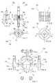
- the device according to the invention consists of a base (1), on which two parallel threaded rods are mounted (2a and 2b), one on the right and the other on the left, inserted through holes made for the purpose on the sides at the end (1a) of the base (1), said threaded rods (2a and 2b) protruding from the end for a certain length, out of one of the two ends (1a) of the base (1).
- a central housing (7) On one side of said gears (5a and 5b) is a central housing (7), on the circular surface of which there are a series of grooves (7a), diametrically opposite each other in pairs, within which two ribs (8) are precisely lodged, these ribs running along the external surface of two drums (9a and 9b), inserted on a median knurled section of the threaded rods (2a and 2b).
- said drums have a circular flange (10), at one end, from which two lobes (11) in a position directly opposite each other protrude, their width being equal to the longitudinal ribs (8) on the same plane as the lobes, said ribs ending at the front in an oblique section.
- the device according to the invention will be supplied by the manufacturer so that both the sliders are already set to beat against the limit microswitches.
- the installer engages one of the two drums, say, the one indicated by number 9a, with its gear-motor (5a) and sets the other drum (9b) in its programming position, with its lobes (11) on the tracks (13a and 13b) of the diaphragm (11b).
- the installer only has to extract the diaphragm (12a) for a short while, so that the drum can rotate until it gets freely inserted within the housing (7) of its gear motor, so that the diaphragm cannot obstruct this manual coupling operation.
- the installer can activate the geared motor which starts to raise the shutter.
- the slider (15b) stays at a standstill compared to its supporting rod (2b), while the slider (15a) translates along its threaded rod (2a).
Landscapes
- Engineering & Computer Science (AREA)
- Structural Engineering (AREA)
- Architecture (AREA)
- Civil Engineering (AREA)
- Operating, Guiding And Securing Of Roll- Type Closing Members (AREA)
- Feeding And Controlling Fuel (AREA)
- Mechanically-Actuated Valves (AREA)
- Gyroscopes (AREA)
- Devices For Conveying Motion By Means Of Endless Flexible Members (AREA)
- Lock And Its Accessories (AREA)
- Blinds (AREA)
- Transmission Devices (AREA)
- Shutters For Cameras (AREA)
Claims (4)
- Mechanische Vorrichtung zur Selbsteinstellung des Endanschlagläufers in der Aufzugsphase bei motorisierten Rolläden, bestehend aus:- einem Untergestell (1), auf dem zwei parallele Gewindestangen (2a und 2b), eine rechtsgängige und eine linksgängige, installiert sind, die durch zwei zu diesem Zweck an den Endseiten (1a) des Untergestells (1) angebrachten Löchern gezogen werden;- zwei Mitnehmertrommeln (9a und 9b), die auf einen mittleren, gerändelten Abschnitt der Gewindestangen aufgeschoben sind, wobei vorgesehen ist, daß jede dieser Mitnehmertrommeln einen runden Basisflansch (10) aufweist, aus dem in diametral entgegengesetzter Position zwei Vorsprünge (11) herausragen, die koplanar zu zwei Längsrippen (8) liegen, die ihrerseits auf der Außenfläche einer jeden Mitnehmertrommel laufen;- zwei lose auf die genannten Gewindestangen (2a und 2b) aufgeschobene Antriebsräder (5a und 5b), deren Zähne (6a und 6b) zum gleichzeitigen Eingriff mit einem Zahnkranz bestimmt sind, der von einem Getriebemotor für die Bewegung des Rolladens in Rotation gebracht wird; es ist vorgesehen, daß jedes Antriebsrad an der zu der jeweiligen Mitnehmertrommel weisenden Kopfflanke einen zentralen, ausgehöhlten Sitz (7) aufweist, auf dessen runder Oberfläche eine Reihe von Nuten (7a) eingelassen sind, in die die vorgenannten Längsrippen (8) der Mitnehmertrommeln genau hineinpassen;- zwei mit den Gewindestangen (2a und 2b) schraubenförmig verbundene Läufer (15a und 15b);- zwei Endanschlag-Microschalter, mit deren Mitwirkung die genannten Läufer (15a und 15b) den Anschlag des Getriebemotors jeweils an den beiden Totpunkten des Rolladenlaufs bestimmen;
Vorrichtung, dadurch gekennzeichnet, daß zwischen den Antriebsrädern (5a und 5b) und den Mitnehmertrommeln (9a und 9b) zwei Platten (11a und 11b) angebracht sind, von denen eine jede ein großes zentrales Fenster (12) aufweist, durch das die Mitnehmertrommeln laufen können, nur wenn sich die Vorsprünge (11) der letzteren sich an die zu diesem Zweck an dem Profil des Fensters (12) befindlichen Einschnitten anordnen, wobei vorgesehen ist, daß auf der Kopfflanke der Platten (11a und 11b), die in Richtung der Mitnehmertrommeln (9a und 9b) gerichtet ist, am Rand des Fensters (12) zwei Ringbahnen (13a und 13b) eingelassen sind, die jeweils in die vorgenannten Einschnitte (13) führen; es ist weiter vorgesehen, daß auf derselben Kopfflanke der Platten zwei Nischen (14) in diametral entgegengesetzter Position eingelassen sind, in die die Vorsprünge (11) der Mitnehmertrommeln in stabiler Ruhestellung eingesetzt werden können. - Mechanische Vorrichtung für die Selbsteinstellung des Endanschlagläufers in der Aufzugsphase von motorisierten Rolläden, nach Anspruch 1, dadurch gekennzeichnet, daß die genannten Gewindestangen (2a und 2b) konstant der Wirkung von zwei vorgespannten Federn (3a und 3b) ausgesetzt sind, die an den Endabschnitten, die aus den genannten Stangen herausstehen, angebracht sind, Stangen die mit einer gewissen Länge an einer der beiden Seiten (1a) des Untergestells (1) herausragen.
- Mechanische Vorrichtung zur Selbsteinstellung des Endanschlagläufers in der Aufzugsphase von motorisierten Rolläden, gemäß den vorgenannten Ansprüchen, dadurch gekennzeichnet, daß die Längsrippen (8) der Mitnehmertrommeln einen schrägen Endabschnitt (8a) aufweisen.
- Mechanische Vorrichtung zur Selbsteinstellung des Endanschlagläufers in der Aufzugsphase von motorisierten Rolläden, gemäß den vorgenannten Ansprüchen, dadurch gekennzeichnet, daß, wenn die Vorsprünge (11) der Mitnehmertrommeln auf die vorgenannten Ringbahnen (13a und 13b) treffen, sich die Rippen (8) der Mitnehmertrommeln für kurze Zeit in die Nuten (7a) der Antriebsräder einfügen, so daß die Verbindung am schrägen Endabschnitt (8a) der Längsrippen (8) erfolgt.
Priority Applications (1)
| Application Number | Priority Date | Filing Date | Title |
|---|---|---|---|
| AT89830060T ATE89644T1 (de) | 1988-03-31 | 1989-02-17 | Mechanische vorrichtung zur selbsteinstellung des endanschlagschiebers beim anheben von motorisierten laeden. |
Applications Claiming Priority (2)
| Application Number | Priority Date | Filing Date | Title |
|---|---|---|---|
| IT00609/88A IT1220229B (it) | 1988-03-31 | 1988-03-31 | Dispositivo meccanico per l'autoregistrazione del cursore di fine corsa,in fase di sollevamento,nelle serrande motorizzate |
| IT60988 | 1988-03-31 |
Publications (3)
| Publication Number | Publication Date |
|---|---|
| EP0335839A2 EP0335839A2 (de) | 1989-10-04 |
| EP0335839A3 EP0335839A3 (de) | 1991-04-24 |
| EP0335839B1 true EP0335839B1 (de) | 1993-05-19 |
Family
ID=11292213
Family Applications (1)
| Application Number | Title | Priority Date | Filing Date |
|---|---|---|---|
| EP89830060A Expired - Lifetime EP0335839B1 (de) | 1988-03-31 | 1989-02-17 | Mechanische Vorrichtung zur Selbsteinstellung des Endanschlagschiebers beim Anheben von motorisierten Läden |
Country Status (5)
| Country | Link |
|---|---|
| EP (1) | EP0335839B1 (de) |
| AT (1) | ATE89644T1 (de) |
| DE (1) | DE68906586T2 (de) |
| ES (1) | ES2043100T3 (de) |
| IT (1) | IT1220229B (de) |
Family Cites Families (2)
| Publication number | Priority date | Publication date | Assignee | Title |
|---|---|---|---|---|
| FR2412483A1 (fr) * | 1977-12-20 | 1979-07-20 | Simu Soc Ind Metal Usine | Dispositif de debrayage et de reglage instantane des fins de course d'un enrouleur automatique |
| DE3003636A1 (de) * | 1980-02-01 | 1981-08-06 | Emil U. Adolf Becker Gmbh & Co Kg, 6349 Sinn | Rohrmotor |
-
1988
- 1988-03-31 IT IT00609/88A patent/IT1220229B/it active
-
1989
- 1989-02-17 AT AT89830060T patent/ATE89644T1/de not_active IP Right Cessation
- 1989-02-17 ES ES89830060T patent/ES2043100T3/es not_active Expired - Lifetime
- 1989-02-17 EP EP89830060A patent/EP0335839B1/de not_active Expired - Lifetime
- 1989-02-17 DE DE89830060T patent/DE68906586T2/de not_active Expired - Fee Related
Also Published As
| Publication number | Publication date |
|---|---|
| EP0335839A3 (de) | 1991-04-24 |
| EP0335839A2 (de) | 1989-10-04 |
| ATE89644T1 (de) | 1993-06-15 |
| DE68906586T2 (de) | 1993-12-09 |
| IT1220229B (it) | 1990-06-06 |
| DE68906586D1 (de) | 1993-06-24 |
| ES2043100T3 (es) | 1993-12-16 |
| IT8800609A0 (it) | 1988-03-31 |
Similar Documents
| Publication | Publication Date | Title |
|---|---|---|
| CA2155657C (en) | Linear motion drive | |
| US4172563A (en) | Shut-off unit in a drive unit for awnings and roller blinds | |
| US4224973A (en) | Drive mechanism, particularly for moving and turning the slats of a blind | |
| DE3153209C2 (de) | Objektivverschluss f}r eine Kamera | |
| KR20190057857A (ko) | 듀얼 스크린 롤블라인드 | |
| CA2203712A1 (en) | A roller blind drive, more particularly for shade producing means | |
| EP0335839B1 (de) | Mechanische Vorrichtung zur Selbsteinstellung des Endanschlagschiebers beim Anheben von motorisierten Läden | |
| CA2021611A1 (en) | Push/pull reset programmer | |
| DE2836938A1 (de) | Elektrisch betriebenes rollo oder rolladen | |
| DE3503816C2 (de) | ||
| DE3871526D1 (de) | Jalousieaufzieh- und wendemechanismus. | |
| US4459893A (en) | Instantaneous rotation device | |
| US5111925A (en) | Device for automatically halting an electric motor after a certain number of revolutions | |
| DE1538287A1 (de) | Zyklisch laufender Synchronmotor | |
| SU515627A2 (ru) | Электромеханическа силова головка | |
| SU1019068A1 (ru) | Устройство дл закрывани люка | |
| SU423190A1 (ru) | Привод электрического выключателя | |
| JP2859074B2 (ja) | スイッチ機構の基準位置設定装置および基準位置設定方法 | |
| DE2211329C3 (de) | Motorantrieb für ein Schaltgerät (z.B. Leistungsschalter) | |
| RU1785873C (ru) | Делительное устройство | |
| SU1301652A1 (ru) | Автоматическое подъемно-поворотное устройство | |
| KR100364248B1 (ko) | 도어의 개폐장치 | |
| KR200220475Y1 (ko) | 축사용 측면 개폐기 | |
| SU1278783A2 (ru) | Шторный фотозатвор | |
| RU2017035C1 (ru) | Автоматическое реверсивное устройство |
Legal Events
| Date | Code | Title | Description |
|---|---|---|---|
| PUAI | Public reference made under article 153(3) epc to a published international application that has entered the european phase |
Free format text: ORIGINAL CODE: 0009012 |
|
| AK | Designated contracting states |
Kind code of ref document: A2 Designated state(s): AT BE CH DE ES FR GB GR LI LU NL SE |
|
| PUAL | Search report despatched |
Free format text: ORIGINAL CODE: 0009013 |
|
| AK | Designated contracting states |
Kind code of ref document: A3 Designated state(s): AT BE CH DE ES FR GB GR LI LU NL SE |
|
| 17P | Request for examination filed |
Effective date: 19911008 |
|
| 17Q | First examination report despatched |
Effective date: 19921030 |
|
| GRAA | (expected) grant |
Free format text: ORIGINAL CODE: 0009210 |
|
| AK | Designated contracting states |
Kind code of ref document: B1 Designated state(s): AT BE CH DE ES FR GB GR LI LU NL SE |
|
| REF | Corresponds to: |
Ref document number: 89644 Country of ref document: AT Date of ref document: 19930615 Kind code of ref document: T |
|
| REF | Corresponds to: |
Ref document number: 68906586 Country of ref document: DE Date of ref document: 19930624 |
|
| ET | Fr: translation filed | ||
| REG | Reference to a national code |
Ref country code: GR Ref legal event code: FG4A Free format text: 3008773 |
|
| REG | Reference to a national code |
Ref country code: ES Ref legal event code: FG2A Ref document number: 2043100 Country of ref document: ES Kind code of ref document: T3 |
|
| PG25 | Lapsed in a contracting state [announced via postgrant information from national office to epo] |
Ref country code: AT Effective date: 19940217 |
|
| PG25 | Lapsed in a contracting state [announced via postgrant information from national office to epo] |
Ref country code: SE Effective date: 19940218 |
|
| PG25 | Lapsed in a contracting state [announced via postgrant information from national office to epo] |
Ref country code: LU Free format text: LAPSE BECAUSE OF NON-PAYMENT OF DUE FEES Effective date: 19940228 Ref country code: LI Effective date: 19940228 Ref country code: CH Effective date: 19940228 |
|
| PLBE | No opposition filed within time limit |
Free format text: ORIGINAL CODE: 0009261 |
|
| STAA | Information on the status of an ep patent application or granted ep patent |
Free format text: STATUS: NO OPPOSITION FILED WITHIN TIME LIMIT |
|
| 26N | No opposition filed | ||
| PG25 | Lapsed in a contracting state [announced via postgrant information from national office to epo] |
Ref country code: NL Effective date: 19940901 |
|
| NLV4 | Nl: lapsed or anulled due to non-payment of the annual fee | ||
| REG | Reference to a national code |
Ref country code: CH Ref legal event code: PL |
|
| EUG | Se: european patent has lapsed |
Ref document number: 89830060.3 Effective date: 19940910 |
|
| PGFP | Annual fee paid to national office [announced via postgrant information from national office to epo] |
Ref country code: GR Payment date: 19960229 Year of fee payment: 8 |
|
| PGFP | Annual fee paid to national office [announced via postgrant information from national office to epo] |
Ref country code: BE Payment date: 19960312 Year of fee payment: 8 |
|
| PG25 | Lapsed in a contracting state [announced via postgrant information from national office to epo] |
Ref country code: BE Effective date: 19970228 |
|
| BERE | Be: lapsed |
Owner name: GAPOSA S.R.L. Effective date: 19970228 |
|
| PG25 | Lapsed in a contracting state [announced via postgrant information from national office to epo] |
Ref country code: GR Free format text: THE PATENT HAS BEEN ANNULLED BY A DECISION OF A NATIONAL AUTHORITY Effective date: 19970831 |
|
| REG | Reference to a national code |
Ref country code: GR Ref legal event code: MM2A Free format text: 3008773 |
|
| PGFP | Annual fee paid to national office [announced via postgrant information from national office to epo] |
Ref country code: GB Payment date: 19980210 Year of fee payment: 10 |
|
| PGFP | Annual fee paid to national office [announced via postgrant information from national office to epo] |
Ref country code: DE Payment date: 19980425 Year of fee payment: 10 |
|
| PGFP | Annual fee paid to national office [announced via postgrant information from national office to epo] |
Ref country code: FR Payment date: 19990129 Year of fee payment: 11 |
|
| PGFP | Annual fee paid to national office [announced via postgrant information from national office to epo] |
Ref country code: ES Payment date: 19990202 Year of fee payment: 11 |
|
| PG25 | Lapsed in a contracting state [announced via postgrant information from national office to epo] |
Ref country code: GB Free format text: LAPSE BECAUSE OF NON-PAYMENT OF DUE FEES Effective date: 19990217 |
|
| GBPC | Gb: european patent ceased through non-payment of renewal fee |
Effective date: 19990217 |
|
| PG25 | Lapsed in a contracting state [announced via postgrant information from national office to epo] |
Ref country code: DE Free format text: LAPSE BECAUSE OF NON-PAYMENT OF DUE FEES Effective date: 19991201 |
|
| PG25 | Lapsed in a contracting state [announced via postgrant information from national office to epo] |
Ref country code: ES Free format text: THE PATENT HAS BEEN ANNULLED BY A DECISION OF A NATIONAL AUTHORITY Effective date: 20000218 |
|
| PG25 | Lapsed in a contracting state [announced via postgrant information from national office to epo] |
Ref country code: FR Free format text: LAPSE BECAUSE OF NON-PAYMENT OF DUE FEES Effective date: 20001031 |
|
| REG | Reference to a national code |
Ref country code: FR Ref legal event code: ST |
|
| REG | Reference to a national code |
Ref country code: ES Ref legal event code: FD2A Effective date: 20020304 |