EP0335825B1 - Procédé et dispositif pour le traitement anarérobe des substrats liquides en deux étapes - Google Patents
Procédé et dispositif pour le traitement anarérobe des substrats liquides en deux étapes Download PDFInfo
- Publication number
- EP0335825B1 EP0335825B1 EP19890730065 EP89730065A EP0335825B1 EP 0335825 B1 EP0335825 B1 EP 0335825B1 EP 19890730065 EP19890730065 EP 19890730065 EP 89730065 A EP89730065 A EP 89730065A EP 0335825 B1 EP0335825 B1 EP 0335825B1
- Authority
- EP
- European Patent Office
- Prior art keywords
- chamber
- fermentation
- substrate
- digestion
- digestion chamber
- Prior art date
- Legal status (The legal status is an assumption and is not a legal conclusion. Google has not performed a legal analysis and makes no representation as to the accuracy of the status listed.)
- Expired - Lifetime
Links
Images

Classifications
-
- C—CHEMISTRY; METALLURGY
- C02—TREATMENT OF WATER, WASTE WATER, SEWAGE, OR SLUDGE
- C02F—TREATMENT OF WATER, WASTE WATER, SEWAGE, OR SLUDGE
- C02F3/00—Biological treatment of water, waste water, or sewage
- C02F3/28—Anaerobic digestion processes
- C02F3/286—Anaerobic digestion processes including two or more steps
-
- C—CHEMISTRY; METALLURGY
- C02—TREATMENT OF WATER, WASTE WATER, SEWAGE, OR SLUDGE
- C02F—TREATMENT OF WATER, WASTE WATER, SEWAGE, OR SLUDGE
- C02F3/00—Biological treatment of water, waste water, or sewage
- C02F3/28—Anaerobic digestion processes
- C02F3/2806—Anaerobic processes using solid supports for microorganisms
-
- C—CHEMISTRY; METALLURGY
- C02—TREATMENT OF WATER, WASTE WATER, SEWAGE, OR SLUDGE
- C02F—TREATMENT OF WATER, WASTE WATER, SEWAGE, OR SLUDGE
- C02F3/00—Biological treatment of water, waste water, or sewage
- C02F3/28—Anaerobic digestion processes
- C02F3/2866—Particular arrangements for anaerobic reactors
- C02F3/2873—Particular arrangements for anaerobic reactors with internal draft tube circulation
-
- C—CHEMISTRY; METALLURGY
- C05—FERTILISERS; MANUFACTURE THEREOF
- C05F—ORGANIC FERTILISERS NOT COVERED BY SUBCLASSES C05B, C05C, e.g. FERTILISERS FROM WASTE OR REFUSE
- C05F3/00—Fertilisers from human or animal excrements, e.g. manure
-
- C—CHEMISTRY; METALLURGY
- C05—FERTILISERS; MANUFACTURE THEREOF
- C05F—ORGANIC FERTILISERS NOT COVERED BY SUBCLASSES C05B, C05C, e.g. FERTILISERS FROM WASTE OR REFUSE
- C05F3/00—Fertilisers from human or animal excrements, e.g. manure
- C05F3/06—Apparatus for the manufacture
-
- C—CHEMISTRY; METALLURGY
- C12—BIOCHEMISTRY; BEER; SPIRITS; WINE; VINEGAR; MICROBIOLOGY; ENZYMOLOGY; MUTATION OR GENETIC ENGINEERING
- C12M—APPARATUS FOR ENZYMOLOGY OR MICROBIOLOGY; APPARATUS FOR CULTURING MICROORGANISMS FOR PRODUCING BIOMASS, FOR GROWING CELLS OR FOR OBTAINING FERMENTATION OR METABOLIC PRODUCTS, i.e. BIOREACTORS OR FERMENTERS
- C12M21/00—Bioreactors or fermenters specially adapted for specific uses
- C12M21/04—Bioreactors or fermenters specially adapted for specific uses for producing gas, e.g. biogas
-
- C—CHEMISTRY; METALLURGY
- C12—BIOCHEMISTRY; BEER; SPIRITS; WINE; VINEGAR; MICROBIOLOGY; ENZYMOLOGY; MUTATION OR GENETIC ENGINEERING
- C12M—APPARATUS FOR ENZYMOLOGY OR MICROBIOLOGY; APPARATUS FOR CULTURING MICROORGANISMS FOR PRODUCING BIOMASS, FOR GROWING CELLS OR FOR OBTAINING FERMENTATION OR METABOLIC PRODUCTS, i.e. BIOREACTORS OR FERMENTERS
- C12M23/00—Constructional details, e.g. recesses, hinges
- C12M23/34—Internal compartments or partitions
-
- C—CHEMISTRY; METALLURGY
- C12—BIOCHEMISTRY; BEER; SPIRITS; WINE; VINEGAR; MICROBIOLOGY; ENZYMOLOGY; MUTATION OR GENETIC ENGINEERING
- C12M—APPARATUS FOR ENZYMOLOGY OR MICROBIOLOGY; APPARATUS FOR CULTURING MICROORGANISMS FOR PRODUCING BIOMASS, FOR GROWING CELLS OR FOR OBTAINING FERMENTATION OR METABOLIC PRODUCTS, i.e. BIOREACTORS OR FERMENTERS
- C12M45/00—Means for pre-treatment of biological substances
- C12M45/06—Means for pre-treatment of biological substances by chemical means or hydrolysis
-
- Y—GENERAL TAGGING OF NEW TECHNOLOGICAL DEVELOPMENTS; GENERAL TAGGING OF CROSS-SECTIONAL TECHNOLOGIES SPANNING OVER SEVERAL SECTIONS OF THE IPC; TECHNICAL SUBJECTS COVERED BY FORMER USPC CROSS-REFERENCE ART COLLECTIONS [XRACs] AND DIGESTS
- Y02—TECHNOLOGIES OR APPLICATIONS FOR MITIGATION OR ADAPTATION AGAINST CLIMATE CHANGE
- Y02A—TECHNOLOGIES FOR ADAPTATION TO CLIMATE CHANGE
- Y02A40/00—Adaptation technologies in agriculture, forestry, livestock or agroalimentary production
- Y02A40/10—Adaptation technologies in agriculture, forestry, livestock or agroalimentary production in agriculture
- Y02A40/20—Fertilizers of biological origin, e.g. guano or fertilizers made from animal corpses
-
- Y—GENERAL TAGGING OF NEW TECHNOLOGICAL DEVELOPMENTS; GENERAL TAGGING OF CROSS-SECTIONAL TECHNOLOGIES SPANNING OVER SEVERAL SECTIONS OF THE IPC; TECHNICAL SUBJECTS COVERED BY FORMER USPC CROSS-REFERENCE ART COLLECTIONS [XRACs] AND DIGESTS
- Y02—TECHNOLOGIES OR APPLICATIONS FOR MITIGATION OR ADAPTATION AGAINST CLIMATE CHANGE
- Y02E—REDUCTION OF GREENHOUSE GAS [GHG] EMISSIONS, RELATED TO ENERGY GENERATION, TRANSMISSION OR DISTRIBUTION
- Y02E50/00—Technologies for the production of fuel of non-fossil origin
- Y02E50/30—Fuel from waste, e.g. synthetic alcohol or diesel
-
- Y—GENERAL TAGGING OF NEW TECHNOLOGICAL DEVELOPMENTS; GENERAL TAGGING OF CROSS-SECTIONAL TECHNOLOGIES SPANNING OVER SEVERAL SECTIONS OF THE IPC; TECHNICAL SUBJECTS COVERED BY FORMER USPC CROSS-REFERENCE ART COLLECTIONS [XRACs] AND DIGESTS
- Y02—TECHNOLOGIES OR APPLICATIONS FOR MITIGATION OR ADAPTATION AGAINST CLIMATE CHANGE
- Y02P—CLIMATE CHANGE MITIGATION TECHNOLOGIES IN THE PRODUCTION OR PROCESSING OF GOODS
- Y02P20/00—Technologies relating to chemical industry
- Y02P20/141—Feedstock
- Y02P20/145—Feedstock the feedstock being materials of biological origin
-
- Y—GENERAL TAGGING OF NEW TECHNOLOGICAL DEVELOPMENTS; GENERAL TAGGING OF CROSS-SECTIONAL TECHNOLOGIES SPANNING OVER SEVERAL SECTIONS OF THE IPC; TECHNICAL SUBJECTS COVERED BY FORMER USPC CROSS-REFERENCE ART COLLECTIONS [XRACs] AND DIGESTS
- Y02—TECHNOLOGIES OR APPLICATIONS FOR MITIGATION OR ADAPTATION AGAINST CLIMATE CHANGE
- Y02W—CLIMATE CHANGE MITIGATION TECHNOLOGIES RELATED TO WASTEWATER TREATMENT OR WASTE MANAGEMENT
- Y02W30/00—Technologies for solid waste management
- Y02W30/40—Bio-organic fraction processing; Production of fertilisers from the organic fraction of waste or refuse
Definitions
- the invention relates to a method for two-stage anaerobic processing of liquid substrates with high organic load according to the preamble of claim 1 and an apparatus for performing the method.
- Waste water, liquid manure and similar liquid substance mixtures with an organic solid content are to be regarded as liquid substrates in this sense.
- the two-stage process of anaerobic processing of substrates is based on nature.
- the macromolecular compounds are first hydrolyzed.
- the group of organisms working in this stage splits the high-molecular compounds such as starch, proteins and fats into low-molecular substances such as sugar, amino acids, glycerin and fatty acids.
- the hydrolysis of the biopolymers takes place very quickly, with the exception of materials containing lignocellulose, since the lignin can only be split very slowly anaerobically.
- the resulting hydrolysis products are further microbially converted to hydrogen, carbon dioxide, carboxylic acids, alcohols and other similar compounds at a pH value below 6 which is favorable for this process.
- German Patent 32 03 445 Such a method is known from German Patent 32 03 445.
- this process provides for a separate arrangement of the reactor for hydrolysis and acidic fermentation on the one hand and that for methane digestion on the other.
- German patents 31 02 739 and 32 14 798 in which both stages take place in the separate chambers of a double-chamber reactor. This is based on a volume distribution according to the underlying time requirement of the acid phase and the methane phase in a ratio of 1:10.
- the division of the reactor is realized in the form of two concentric chambers which are connected to one another in the bottom area.
- the disadvantage here is that with this arrangement it is not possible to circulate the liquids in the digester and that the fermentation reactor is charged from above. The latter is disadvantageous with regard to the desired, as far as possible, sedimentation of solids in the fermentation reactor, which is decisive for the time required for the subsequent methane digestion.
- a device for the anaerobic treatment of sludge and waste water in which a reaction chamber for carrying out the methane fermentation and a separation chamber are provided in the cylindrical container, in which separation effects by sedimentation and flotation are used.
- the wall separating the reaction space from the separation chamber has through openings in its lower part and below this a collection space for the thickened sludge is formed in the separation chamber.
- a multi-stage bioreactor in which - as in the previously treated device - only a single sludge discharge is provided, in this case from the fermentation chamber.
- the fermentation chamber is divided into two stages, in which different flows are set.
- the invention has for its object to develop a method of the generic type in such a way that the overall process of substrate preparation is accelerated. Furthermore, an apparatus for carrying out this method is to be specified which is of the simplest possible construction and which, with regard to the optimal sizes of the fermentation and digestion chamber, easily conforms to existing conditions, i.e. can be adapted to the degree of organic contamination of the substrate to be treated.
- An essential feature of the invention is that the substrate to be treated is passed through the two chambers of the reactor according to the upflow principle.
- the substrate is fed to the fermentation chamber via a feed line which opens into the fermentation chamber at about a third of the height of the liquid level or below it. Hydrolysis and acidic fermentation take place in this first chamber.
- the fermentation sludge settles particularly effectively due to the applied upflow process and can be treated after washing by washing or composting.
- the resulting fermentation gas (H2, CO2, H2S) flows out of the reactor head.
- the liquid already largely freed from organic solids flows freely into the second chamber and is guided through a line so that it in turn enters this chamber at about a third of the level of the liquid or below, in which the acetogenic phase and the methane formation occur.
- Settled digested sludge is removed from the floor if necessary.
- the biogas (CH4 and CO2) that forms during digestion leaves the reactor at the top.
- the free overflowing fermentation water can be discharged into the sewage system according to the discharge conditions e.g. be treated aerobically.
- the residence time of the liquid in the reactor chambers depends on the degree of organic pollution and the rate of hydrolysis and fermentation of the organic substances, the first stage being 1.5 to 5 times faster than the second.
- the more organic solids the substrate contains the longer the digestion process, i.e. the smaller the ratio of the volumes of the fermentation chamber and the fermentation chamber.
- this ratio depends on the desired degree of preparation of the substrate, which can be expressed exactly in the difference between the initial and final values for the chemical and biological oxygen demand (COD or BOD5).
- COD or BOD5 chemical and biological oxygen demand
- a ratio of 1: 2 can be regarded as favorable.
- the cleaning process can be carried out both mesophilic and thermophilic.
- the effectiveness of the digestion process can be improved by arranging a layer of a porous, liquid-permeable solid with a large specific surface area in the digestion chamber. Large numbers of microorganisms can settle on the surface of such a "filter body". This ensures a high bacterial density, minimizing the risk of these bacteria flushing out with the removal of the cleaned waste water.
- the "filter body” e.g. can be formed as a bed of solid particles on a sieve tray, it is advisable to temporarily reverse the conveying direction of the forced circulation in order to achieve a backwashing effect.
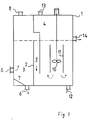
- a round or square container 1 with a partition 2, which divides the container 1 into two chambers 3, 4, is suitable for carrying out the method.
- the smaller chamber serves as a fermentation chamber 3 and the larger one as a fermentation chamber 4.
- a connection 14 for the drainage from the digester 4 is arranged in the wall of the container 1. The liquid level in the two chambers 3, 4 is therefore the same.
- the substrate to be cleaned is fed to the fermentation chamber 3 via a connection 5 which is arranged in the lower third of the liquid level at a distance from the reactor bottom in the outer wall of the container 1, so that the substrate is introduced according to the advantageous upstream principle and a substantial exemption from those contained therein Solids can take place before the liquid remaining after hydrolysis and acid fermentation enters the digester 4.
- the solids settle on the bottom of the fermentation chamber 3, which is advantageously equipped with a sloping floor 7, so that the sedimented fermentation sludge can be drawn off through the discharge nozzle 6 in the tank bottom.
- the resulting fermentation gas collects above the liquid level in the fermentation chamber 3 and is discharged via the connection piece 8.
- the overflow 9 opens into the digestion chamber 4 at a distance from the reactor floor at about a third of the height of the liquid level, so that the pretreated substrate is also passed through the digestion chamber 4 according to the upflow principle.
- it is very expedient to ensure forced circulation in the digestion chamber 4.
- This is designed according to the figure as a stirrer 10, which is arranged in a tubular jacket 11, so that a safe, targeted circulation is given.
- the stirrer 10 and the jacket 11 are expediently designed in such a way that an upstream velocity of 0.8 to 1.3 m / h prevails outside the tubular jacket 11 in order to obtain the greatest possible bacterial density.
- the conveying direction of the stirrer 10 is therefore preferably set to downward conveyance.
- the digester gas that forms advantageously leaves the digester 4 separately from the fermentation gas through the nozzle 13 at the head of the reactor 1.
- the digested liquid runs through the nozzle 14 as waste water.
- feed pipe 5 and discharge pipe 14 are close together and are integrated in a heat exchanger in such a way that the thermal energy emerging from the tank 1 with the waste water can be used for preheating the freshly supplied substrate.
- the preferred embodiment of the reactor according to the invention shown in FIG. 2 differs from FIG. 1 only in that a bed 15 of solid particles with a porous surface resting on a sieve plate 16 is arranged around the jacket 11 of the stirring device 10. Microorganisms settle on the porous surface of the solid particles, for example made of ceramic, which are no longer easily washed out of the digestion chamber 4 via the waste water connection 14, but intensify the digestion process. In order to avoid clogging of the solid bed 15 acting as a filter body, the conveying direction of the stirring device 10 should be temporarily reversed so that the backwashing effect leads to a sufficient removal of organic solids from the bed 15.
Landscapes
- Life Sciences & Earth Sciences (AREA)
- Chemical & Material Sciences (AREA)
- Organic Chemistry (AREA)
- Engineering & Computer Science (AREA)
- Health & Medical Sciences (AREA)
- Microbiology (AREA)
- Zoology (AREA)
- Bioinformatics & Cheminformatics (AREA)
- Wood Science & Technology (AREA)
- Genetics & Genomics (AREA)
- General Health & Medical Sciences (AREA)
- Biodiversity & Conservation Biology (AREA)
- Biochemistry (AREA)
- General Engineering & Computer Science (AREA)
- Biotechnology (AREA)
- Biomedical Technology (AREA)
- Molecular Biology (AREA)
- Water Supply & Treatment (AREA)
- Environmental & Geological Engineering (AREA)
- Sustainable Development (AREA)
- Hydrology & Water Resources (AREA)
- Oil, Petroleum & Natural Gas (AREA)
- General Chemical & Material Sciences (AREA)
- Manufacturing & Machinery (AREA)
- Clinical Laboratory Science (AREA)
- Treatment Of Sludge (AREA)
- Purification Treatments By Anaerobic Or Anaerobic And Aerobic Bacteria Or Animals (AREA)
- Crystals, And After-Treatments Of Crystals (AREA)
Claims (17)
- Procédé pour le traitement anaérobie, en deux étapes, de substrats liquides à forte charge organique dans un réacteur unique comportant deux chambres séparées par une paroi, l'hydrolyse et la fermentation acide ayant lieu dans la première chambre (chambre de fermentation) et la formation de méthane dans la seconde (chambre de putréfaction), des sédiments solides étant évacués à proximité du fond de la chambre de fermentation, l'introduction du substrat dans la chambre de putréfaction se faisant à partir de la partie supérieure de la chambre de fermentation, les eaux usagées générées par le substrat traité étant par ailleurs évacuées à la partie supérieure de la chambre de putréfaction, les gaz de fermentation et de putréfaction étant évacués au-dessus du niveau de liquide, caractérisé en ce que l'alimentation en substrat de la chambre de fermentation s'effectue à distance du fond de cette chambre, à une hauteur située au plus à un tiers du niveau du liquide dans cette chambre, que l'alimentation de la chambre de putréfaction avec un substrat débarrassé dans une large mesure de matières solides s'effectue à distance du fond de la chambre de putréfaction, à une hauteur au plus égale à un tiers du niveau du liquide dans cette chambre, que des sédiments solides sont évacués de la chambre de putréfaction et que le substrat est soumis à une circulation forcée dans la chambre de putréfaction.
- Procédé selon la revendication 1, caractérisé en ce que le courant ascendant dans la chambre de putréfaction est maintenu entre 0,8 et 1,3 m/h.
- Procédé selon une des revendications 1 ou 2, caractérisé en ce que le traitement des eaux usagées est effectué de façon continue.
- Procédé selon une des revendications 1 à 3, caractérisé en ce que le gaz de fermentation et le gaz de putréfaction sont collectés et évacués séparément.
- Procédé selon une des revendications 1 à 4, caractérisé en ce que l'on fait passer le substrat à travers un amas de granules solides dont la surface est peuplée de micro-organismes.
- Procédé selon la revendication 5, caractérisé en ce que l'on inverse de temps en temps la direction du courant du substrat dans la chambre de putréfaction.
- Réacteur biologique pour la mise en oeuvre du procédé selon la revendication 1, consistant en une enceinte (1) avec une première chambre (chambre de fermentation 3) pour l'hydrolyse et la fermentation acide, et avec une seconde chambre (chambre de putréfaction 4) séparée de la première par une paroi (2) pour la génération de méthane, avec une conduite d'alimentation (5) pour alimenter la chambre de fermentation (3) avec un substrat liquide et avec une conduite d'évacuation (14) pour évacuer le substrat traité de la chambre de putréfaction (4), avec une conduite d'évacuation de gaz (8, 13) pour le gaz de fermentation et le gaz de putréfaction produits,et avec un dispositif d'évacuation (6) pour la boue qui se forme à la partie basse de la chambre de fermentation (3), caractérisé en ce que l'entrée de la conduite d'alimentation en substrat (5) est située dans la chambre de fermentation (3) à distance du fond de celle-ci à une hauteur au plus égale à un tiers de la hauteur du niveau du liquide dans cette chambre, que le passage de la chambre de fermentation (3) à la chambre de putréfaction (4) est un trop-plein (9) en forme de tuyau s'étendant vers le bas dans la chambre de putréfaction (4) jusqu'à environ au moins un tiers de la hauteur de la conduite (14) d'évacuation des eaux usagées, laquelle forme également un trop-plein, et se termine à distance du fond de la chambre de putréfaction (4), que cette dernière contient un dispositif de circulation forcée, et qu'un nable de vidange (12) pour la boue de putréfaction est prévu dans le fond de la chambre de putréfaction (4).
- Réacteur biologique selon la revendication 7, caractérisé en ce que le dispositif de circulation forcée est réalisé sous forme d'un agitateur (10) entouré d'un tube vertical (11) dont les extrémités sont situées à distance du fond du réacteur ainsi que de la surface du liquide.
- Réacteur biologique selon une des revendications 7 ou 8, caractérisé en ce que la paroi (2) séparant les deux chambres (3, 4) est disposée de façon à ce que le rapport du volume de la chambre de fermentation (3) à celui de la chambre de putréfaction (4) soit compris entre 1 : 1,5 et 1 : 5.
- Réacteur biologique selon une des revendications 7 à 9, caractérisé en ce que le dispositif de circulation forcée est dimensionné pour un courant ascendant compris entre 0,8 et 1,3 m/h.
- Réacteur biologique selon une des revendications 7 à 10, caractérisé en ce que la conduite d'alimentation en substrat (5) et la conduite d'évacuation (14) des eaux usagées sortent côte à côte de l'enceinte (1) du réacteur et sont intégrées dans la partie réceptrice, respectivement distributrice de chaleur d'un échangeur de chaleur.
- Réacteur biologique selon une des revendications 7 à 11, caractérisé en ce que tant la chambre de fermentation (3) que celle de putréfaction (4) comporte une conduite de gaz séparée (8 respectivement 13).
- Réacteur biologique selon une des revendications 7 à 12, caractérisé en ce que la chambre de putréfaction (4) contient une couche formée d'un amas granuleux (15) de particules solides à surface poreuse.
- Réacteur biologique selon la revendication 13, caractérisé en ce que les particules solides sont en céramique.
- Réacteur biologique selon une des revendications 13 ou 14, caractérisé en ce que l'amas granuleux (15) est disposé sur un fond intermédiaire formant passoire (16).
- Réacteur biologique selon une des revendications 13 à 15, caractérisé en ce que l'amas granuleux (15) s'étend sur toute la section transversale de la chambre de putréfaction (4).
- Réacteur biologique selon la revendication 10 et une des revendications 13 à 16, caractérisé en ce que l'amas granuleux (15) est disposé autour du tube (11) entourant l'agitateur (10).
Priority Applications (1)
| Application Number | Priority Date | Filing Date | Title |
|---|---|---|---|
| AT89730065T ATE80134T1 (de) | 1988-03-23 | 1989-03-10 | Verfahren und vorrichtung zur zweistufigen anaeroben aufbereitung fluessiger substrate. |
Applications Claiming Priority (2)
| Application Number | Priority Date | Filing Date | Title |
|---|---|---|---|
| DE19883810250 DE3810250A1 (de) | 1988-03-23 | 1988-03-23 | Verfahren und vorrichtung zur zweistufigen anaeroben aufbereitung fluessiger substrate |
| DE3810250 | 1988-03-23 |
Publications (2)
| Publication Number | Publication Date |
|---|---|
| EP0335825A1 EP0335825A1 (fr) | 1989-10-04 |
| EP0335825B1 true EP0335825B1 (fr) | 1992-09-02 |
Family
ID=6350745
Family Applications (1)
| Application Number | Title | Priority Date | Filing Date |
|---|---|---|---|
| EP19890730065 Expired - Lifetime EP0335825B1 (fr) | 1988-03-23 | 1989-03-10 | Procédé et dispositif pour le traitement anarérobe des substrats liquides en deux étapes |
Country Status (4)
| Country | Link |
|---|---|
| EP (1) | EP0335825B1 (fr) |
| AT (1) | ATE80134T1 (fr) |
| DE (2) | DE3810250A1 (fr) |
| ES (1) | ES2034743T3 (fr) |
Cited By (2)
| Publication number | Priority date | Publication date | Assignee | Title |
|---|---|---|---|---|
| KR100827946B1 (ko) | 2008-01-11 | 2008-05-08 | 디에스케이엔지니어링(주) | 포트 인 포트 구조의 바이오 가스 플랜트 장치 |
| CN102153196A (zh) * | 2011-04-08 | 2011-08-17 | 中国人民解放军后勤工程学院 | 加热式一体化污水处理装置 |
Families Citing this family (19)
| Publication number | Priority date | Publication date | Assignee | Title |
|---|---|---|---|---|
| ES2088368B1 (es) * | 1995-01-20 | 1997-06-01 | Munoz Aurelio Hernandez | Proceso de digestion anaerobia, en dos fases, de fangos procedentes de la depuracion de aguas residuales con contenido organico. |
| EP0838436A1 (fr) * | 1996-10-22 | 1998-04-29 | TAKASHIMA, Yasuhide | Procédé et dispositif de purification automatique des eaux usées par fermentation exhaustive |
| KR100646076B1 (ko) * | 1999-07-30 | 2006-11-13 | 다이신셋케이 가부시키가이샤 | 2상형 메탄발효반응장치 |
| US6905600B2 (en) | 2001-11-16 | 2005-06-14 | Ch2M Hill, Inc. | Method and apparatus for the treatment of particulate biodegradable organic waste |
| GB0326062D0 (en) * | 2003-11-07 | 2003-12-10 | Saroko Technologies Ltd | Bioreactor |
| DE102005054323B4 (de) | 2005-11-11 | 2008-02-21 | Wilhelm Gantefort | Fermenter zur Erzeugung von Biogas aus organischem Material |
| DE102006005066B3 (de) * | 2006-02-03 | 2007-10-18 | Perske, Günter | Vorrichtung und Verfahren zur Erzeugung von Biogas aus organischen Stoffen |
| ES2301370B1 (es) * | 2006-06-21 | 2009-11-10 | Julio Biotratamientos De Aguas, S.L. | Equipo para depuracion biologica de aguas residuales. |
| WO2008099227A1 (fr) * | 2007-02-12 | 2008-08-21 | Ingenieurgemeischaft Luxemburg Sarl | Procédé et dispositif de production de biogaz à partir de biomasse |
| US7968760B2 (en) | 2007-03-16 | 2011-06-28 | Ch2M Hill, Inc. | Treatment of particulate biodegradable organic waste by thermal hydrolysis using condensate recycle |
| DE102007024378B4 (de) | 2007-05-23 | 2009-06-04 | Beck, Jürgen, Dr. | Fermenter zur Erzeugung von Biogas aus pumpbarem organischen Material |
| DE102010010294A1 (de) * | 2010-03-04 | 2011-09-08 | Fachhochschule Flensburg | Verfahren und Vorrichtung zur anaeroben Fermentation |
| EP2460771A1 (fr) * | 2010-12-06 | 2012-06-06 | National University of Ireland, Galway | Réacteur anaérobique pour traitement psychrophile et/ou mésophile des eaux usées |
| DE102012222589A1 (de) | 2012-12-07 | 2014-06-12 | Planungsbüro Rossow Gesellschaft für erneuerbare Energien mbH | Substrataufschluss für biogasanlagen in einem anmisch- und kombihydrolysebehälter |
| DE102013006717A1 (de) | 2013-04-19 | 2014-10-23 | Wabio Technologie Gmbh | Verfahren zur Methanfermentation und Anordnung zur Durchführung des Verfahrens |
| CN110734131A (zh) * | 2018-07-18 | 2020-01-31 | 光大水务(深圳)有限公司 | 基于厌氧/缺氧池的生物填料搅拌工艺 |
| CN110316823B (zh) * | 2019-08-07 | 2022-03-29 | 大连海事大学 | 一种船舶废气脱硫、脱硝废液与船舶生活污水的同步处理装置与同步处理方法 |
| DE102019133040A1 (de) * | 2019-12-04 | 2021-06-10 | Hans Otto Mieth | Biogasreaktor und Verfahren zu dessen Betrieb |
| CN111646639A (zh) * | 2020-05-25 | 2020-09-11 | 广东维清环境工程有限公司 | 一种预充氧-两级厌氧膜生物反应器的养殖废水处理工艺 |
Family Cites Families (13)
| Publication number | Priority date | Publication date | Assignee | Title |
|---|---|---|---|---|
| DE581860C (de) * | 1932-03-22 | 1933-08-03 | Max Kusch Dr Ing | Zweistufiger Schlammfaulraum |
| IE772633L (en) * | 1977-12-29 | 1979-06-29 | Sweeney J J Newell P J | Treating waste products |
| DE3102739C2 (de) * | 1981-01-28 | 1983-10-20 | Messerschmitt-Bölkow-Blohm GmbH, 8000 München | Verfahren und Vorrichtung zur anaeroben Aufbereitung von Abfall |
| DE3214798C2 (de) * | 1981-01-28 | 1984-10-04 | Messerschmitt-Bölkow-Blohm GmbH, 8000 München | Verfahren und Vorrichtung zur anaeroben Aufbereitung von Abfall |
| DD200133A1 (de) * | 1981-08-19 | 1983-03-23 | Friedrich Liepe | Vorrichtung zur anaeroben behandlung von schlaemmen und abwaessern |
| DE8129366U1 (de) * | 1981-10-07 | 1982-03-25 | Ökotherm Vertriebs-Gesellschaft mbH, 2357 Hagen | Vorrichtung zur verarbeitung einer biomasse zu biogas |
| DD210891A1 (de) * | 1982-10-21 | 1984-06-27 | Dresden Komplette Chemieanlag | Vorrichtung zur anaeroben aufbereitung von abwaessern |
| DE3309299A1 (de) * | 1983-03-16 | 1984-12-06 | Klöckner-Werke AG, 4100 Duisburg | Verfahren und vorrichtung zum anaeroben behandeln von rohschlamm bzw. hochbelastetem abwasser |
| DE3561552D1 (en) * | 1984-07-28 | 1988-03-10 | Heinz Harrendorf | Process and device for anaerobically treating organic substrates in order to produce biogas |
| DE3508274A1 (de) * | 1985-03-08 | 1986-09-11 | Kernforschungsanlage Jülich GmbH, 5170 Jülich | Saeulenreaktor fuer anaerobe abbauprozesse |
| DE3530332A1 (de) * | 1985-08-24 | 1986-05-15 | Heinz Prof. Dr.-Ing. 1000 Berlin Brauer | Puls-bioreaktor mit schwammelementen fuer die fixierung von mikroorganismen oder enzymen |
| DE3623431A1 (de) * | 1986-02-12 | 1988-01-28 | Caro Thomas | Mehrstufiger bioreaktor |
| DE3604415A1 (de) * | 1986-02-12 | 1987-08-13 | Caro Thomas | Mehrstufiges verfahren und apparatur zur umwandlung von organischen und anorganischen stoffen durch katalysatore |
-
1988
- 1988-03-23 DE DE19883810250 patent/DE3810250A1/de not_active Withdrawn
-
1989
- 1989-03-10 EP EP19890730065 patent/EP0335825B1/fr not_active Expired - Lifetime
- 1989-03-10 AT AT89730065T patent/ATE80134T1/de not_active IP Right Cessation
- 1989-03-10 ES ES89730065T patent/ES2034743T3/es not_active Expired - Lifetime
- 1989-03-10 DE DE8989730065T patent/DE58902173D1/de not_active Expired - Fee Related
Cited By (3)
| Publication number | Priority date | Publication date | Assignee | Title |
|---|---|---|---|---|
| KR100827946B1 (ko) | 2008-01-11 | 2008-05-08 | 디에스케이엔지니어링(주) | 포트 인 포트 구조의 바이오 가스 플랜트 장치 |
| CN102153196A (zh) * | 2011-04-08 | 2011-08-17 | 中国人民解放军后勤工程学院 | 加热式一体化污水处理装置 |
| CN102153196B (zh) * | 2011-04-08 | 2012-07-25 | 中国人民解放军后勤工程学院 | 加热式一体化污水处理装置 |
Also Published As
| Publication number | Publication date |
|---|---|
| DE58902173D1 (de) | 1992-10-08 |
| ATE80134T1 (de) | 1992-09-15 |
| DE3810250A1 (de) | 1989-10-05 |
| EP0335825A1 (fr) | 1989-10-04 |
| ES2034743T3 (es) | 1993-04-01 |
Similar Documents
| Publication | Publication Date | Title |
|---|---|---|
| EP0335825B1 (fr) | Procédé et dispositif pour le traitement anarérobe des substrats liquides en deux étapes | |
| EP0132649B1 (fr) | Procédé pour la purification biologique anaérobie d'eau usée | |
| DE3137055A1 (de) | "verfahren und vorrichtung zur biologischen reinigung von abwasser" | |
| EP1986963B1 (fr) | Procédé et dispositif pour liquéfier en continu des substances organiques solides | |
| WO2009117754A1 (fr) | Procédé pour la production de biogaz | |
| EP0255642A2 (fr) | Réacteur de dispersion liquide-gaz | |
| DE4415017C2 (de) | Zweistufiger Kombi-Biogasreaktor zur Aufbereitung pflanzlicher und tierischer Biomasse, insbesondere Gülle | |
| EP1531123A2 (fr) | Méthode et installation pour traiter des eaux de déchet de bateaux | |
| DE102007004135A1 (de) | Verfahren und Vorrichtung zur Vergärung von Biomassen | |
| EP0139976A1 (fr) | Appareil pour la décomposition anaérobie de substances organiques | |
| CH619675A5 (fr) | ||
| DE3603792C2 (fr) | ||
| DE19623592C1 (de) | Verfahren und Reaktor zur kontinuierlichen mikrobiologischen Behandlung von hochbelastetem Abwasser mittels schwimmfähigem Trägermaterial | |
| EP0474325A1 (fr) | Procédé et appareil pour la purification biologique anaérobie d'eaux chargées de composés organiques | |
| EP1657222A1 (fr) | Méthode et dispositif de traitement biologique d'une suspension dans un bioréacteur. | |
| DE19631796A1 (de) | Verfahren und Vorrichtung zur Reinigung von Abwassern | |
| EP0501355B1 (fr) | Processus de traitement anaérobie de l'eau, notamment de l'élimination par micro-organismes du nitrate de l'eau potable | |
| DD200133A1 (de) | Vorrichtung zur anaeroben behandlung von schlaemmen und abwaessern | |
| EP0058247B1 (fr) | Procédé et dispositif pour la purification anaérobie de liquides contenant des substances organiques | |
| DE3139914A1 (de) | Verfahren und vorrichtung zur verarbeitung einer biomasse zu biogas. | |
| DE3306149A1 (de) | Vorrichtung zur anaeroben behandlung von abwaessern | |
| EP0659695B1 (fr) | Procédé pour le traitement des boues des eaux d'égou | |
| DE3520652A1 (de) | Klaerbecken zur aeroben oder fakultativen reinigung organischer abwaesser | |
| DE2335538B1 (de) | Verfahren zur Beschleunigung und Intensivierung biologischer Abbauvorgaenge | |
| DE3316720A1 (de) | Fermenter und verfahren zum kontinuierlichen, anaeroben, biologischen abbau von abwaessern |
Legal Events
| Date | Code | Title | Description |
|---|---|---|---|
| PUAI | Public reference made under article 153(3) epc to a published international application that has entered the european phase |
Free format text: ORIGINAL CODE: 0009012 |
|
| AK | Designated contracting states |
Kind code of ref document: A1 Designated state(s): AT BE CH DE ES GB IT LI LU NL |
|
| 17P | Request for examination filed |
Effective date: 19890816 |
|
| 17Q | First examination report despatched |
Effective date: 19901207 |
|
| GRAA | (expected) grant |
Free format text: ORIGINAL CODE: 0009210 |
|
| AK | Designated contracting states |
Kind code of ref document: B1 Designated state(s): AT BE CH DE ES GB IT LI LU NL |
|
| PG25 | Lapsed in a contracting state [announced via postgrant information from national office to epo] |
Ref country code: BE Effective date: 19920902 |
|
| REF | Corresponds to: |
Ref document number: 80134 Country of ref document: AT Date of ref document: 19920915 Kind code of ref document: T |
|
| REF | Corresponds to: |
Ref document number: 58902173 Country of ref document: DE Date of ref document: 19921008 |
|
| ITF | It: translation for a ep patent filed |
Owner name: GUZZI E RAVIZZA S.R.L. |
|
| GBT | Gb: translation of ep patent filed (gb section 77(6)(a)/1977) |
Effective date: 19921207 |
|
| PG25 | Lapsed in a contracting state [announced via postgrant information from national office to epo] |
Ref country code: LU Free format text: LAPSE BECAUSE OF NON-PAYMENT OF DUE FEES Effective date: 19930331 |
|
| REG | Reference to a national code |
Ref country code: ES Ref legal event code: FG2A Ref document number: 2034743 Country of ref document: ES Kind code of ref document: T3 |
|
| PLBE | No opposition filed within time limit |
Free format text: ORIGINAL CODE: 0009261 |
|
| STAA | Information on the status of an ep patent application or granted ep patent |
Free format text: STATUS: NO OPPOSITION FILED WITHIN TIME LIMIT |
|
| 26N | No opposition filed | ||
| PGFP | Annual fee paid to national office [announced via postgrant information from national office to epo] |
Ref country code: GB Payment date: 19990212 Year of fee payment: 11 |
|
| PGFP | Annual fee paid to national office [announced via postgrant information from national office to epo] |
Ref country code: DE Payment date: 19990224 Year of fee payment: 11 |
|
| PGFP | Annual fee paid to national office [announced via postgrant information from national office to epo] |
Ref country code: AT Payment date: 19990225 Year of fee payment: 11 |
|
| PGFP | Annual fee paid to national office [announced via postgrant information from national office to epo] |
Ref country code: NL Payment date: 19990228 Year of fee payment: 11 |
|
| PGFP | Annual fee paid to national office [announced via postgrant information from national office to epo] |
Ref country code: CH Payment date: 19990301 Year of fee payment: 11 |
|
| PGFP | Annual fee paid to national office [announced via postgrant information from national office to epo] |
Ref country code: ES Payment date: 19990318 Year of fee payment: 11 |
|
| PG25 | Lapsed in a contracting state [announced via postgrant information from national office to epo] |
Ref country code: GB Free format text: LAPSE BECAUSE OF NON-PAYMENT OF DUE FEES Effective date: 20000310 Ref country code: AT Free format text: LAPSE BECAUSE OF NON-PAYMENT OF DUE FEES Effective date: 20000310 |
|
| PG25 | Lapsed in a contracting state [announced via postgrant information from national office to epo] |
Ref country code: ES Free format text: LAPSE BECAUSE OF NON-PAYMENT OF DUE FEES Effective date: 20000311 |
|
| PG25 | Lapsed in a contracting state [announced via postgrant information from national office to epo] |
Ref country code: LI Free format text: LAPSE BECAUSE OF NON-PAYMENT OF DUE FEES Effective date: 20000331 Ref country code: CH Free format text: LAPSE BECAUSE OF NON-PAYMENT OF DUE FEES Effective date: 20000331 |
|
| PG25 | Lapsed in a contracting state [announced via postgrant information from national office to epo] |
Ref country code: NL Free format text: LAPSE BECAUSE OF NON-PAYMENT OF DUE FEES Effective date: 20001001 |
|
| GBPC | Gb: european patent ceased through non-payment of renewal fee |
Effective date: 20000310 |
|
| REG | Reference to a national code |
Ref country code: CH Ref legal event code: PL |
|
| NLV4 | Nl: lapsed or anulled due to non-payment of the annual fee |
Effective date: 20001001 |
|
| PG25 | Lapsed in a contracting state [announced via postgrant information from national office to epo] |
Ref country code: DE Free format text: LAPSE BECAUSE OF NON-PAYMENT OF DUE FEES Effective date: 20010103 |
|
| REG | Reference to a national code |
Ref country code: ES Ref legal event code: FD2A Effective date: 20010910 |
|
| PG25 | Lapsed in a contracting state [announced via postgrant information from national office to epo] |
Ref country code: IT Free format text: LAPSE BECAUSE OF NON-PAYMENT OF DUE FEES;WARNING: LAPSES OF ITALIAN PATENTS WITH EFFECTIVE DATE BEFORE 2007 MAY HAVE OCCURRED AT ANY TIME BEFORE 2007. THE CORRECT EFFECTIVE DATE MAY BE DIFFERENT FROM THE ONE RECORDED. Effective date: 20050310 |