EP0335810A1 - Eckverbindung für einen Schneidtisch - Google Patents
Eckverbindung für einen Schneidtisch Download PDFInfo
- Publication number
- EP0335810A1 EP0335810A1 EP89420112A EP89420112A EP0335810A1 EP 0335810 A1 EP0335810 A1 EP 0335810A1 EP 89420112 A EP89420112 A EP 89420112A EP 89420112 A EP89420112 A EP 89420112A EP 0335810 A1 EP0335810 A1 EP 0335810A1
- Authority
- EP
- European Patent Office
- Prior art keywords
- tubes
- foot tube
- connecting piece
- assembly
- corner assembly
- Prior art date
- Legal status (The legal status is an assumption and is not a legal conclusion. Google has not performed a legal analysis and makes no representation as to the accuracy of the status listed.)
- Granted
Links
- 238000005520 cutting process Methods 0.000 title claims description 11
- 239000002184 metal Substances 0.000 claims abstract description 9
- 238000009432 framing Methods 0.000 claims description 31
- 230000000149 penetrating effect Effects 0.000 claims description 7
- 238000003466 welding Methods 0.000 claims description 6
- 210000000056 organ Anatomy 0.000 claims 1
- 230000002787 reinforcement Effects 0.000 claims 1
- 238000007789 sealing Methods 0.000 claims 1
- 230000006978 adaptation Effects 0.000 description 3
- 238000002788 crimping Methods 0.000 description 3
- 230000000712 assembly Effects 0.000 description 2
- 238000000429 assembly Methods 0.000 description 2
- 238000005553 drilling Methods 0.000 description 2
- 230000000903 blocking effect Effects 0.000 description 1
- 235000013305 food Nutrition 0.000 description 1
- 239000010794 food waste Substances 0.000 description 1
- 238000009776 industrial production Methods 0.000 description 1
- 238000003780 insertion Methods 0.000 description 1
- 230000037431 insertion Effects 0.000 description 1
- 238000004519 manufacturing process Methods 0.000 description 1
- 239000000463 material Substances 0.000 description 1
- 235000013372 meat Nutrition 0.000 description 1
- 238000000034 method Methods 0.000 description 1
- 230000010355 oscillation Effects 0.000 description 1
- 230000002035 prolonged effect Effects 0.000 description 1
Images


Classifications
-
- F—MECHANICAL ENGINEERING; LIGHTING; HEATING; WEAPONS; BLASTING
- F16—ENGINEERING ELEMENTS AND UNITS; GENERAL MEASURES FOR PRODUCING AND MAINTAINING EFFECTIVE FUNCTIONING OF MACHINES OR INSTALLATIONS; THERMAL INSULATION IN GENERAL
- F16B—DEVICES FOR FASTENING OR SECURING CONSTRUCTIONAL ELEMENTS OR MACHINE PARTS TOGETHER, e.g. NAILS, BOLTS, CIRCLIPS, CLAMPS, CLIPS OR WEDGES; JOINTS OR JOINTING
- F16B12/00—Jointing of furniture or the like, e.g. hidden from exterior
- F16B12/44—Leg joints; Corner joints
- F16B12/50—Metal corner connections
Definitions
- the present invention relates to cutting tables, comprising an upper plate of a suitable material on which one can cut meat or other foods. These tables are commonly used in butcher shops, delicatessens, restaurant or community kitchens.
- the upper plate is placed on a frame.
- the chassis includes frame tubes, forming a substantially rectangular frame. At each angle where two adjacent framing tubes are connected, a foot tube is secured, perpendicular to the two framing tubes.
- the upper plate must be held by stop latches, integral with the frame, and defining lateral stops against which the edges of the upper plate come to bear.
- a classic solution consists in making a mechanically welded frame, on which we weld stop blocks, and on which we also weld foot tubes. This solution leads to an increase in the number of welds to be made. For industrial production of a full range of tables of different dimensions, it is necessary to have large stocks of fully assembled cutting tables.
- foot tubes are removable.
- a connecting piece of molded metal is crimped into the framing tubes, and thus connects two successive tubes.
- the part also includes stop cleats, and means for fixing and adapting a foot tube.
- the crimped connection between the connecting piece and the framing tubes constitutes an unreliable connection, which tends to present a clearance; crimping is an expensive technique, especially since the parts have relatively complex shapes and that crimping requires a certain precision; the connecting piece, made of molded metal, does not generally adapt perfectly to the ends of the frame tubes, and this results in the existence of dirt nests, which are unacceptable for uses in community kitchens. Also, the fact that the connecting piece is made of a molded metal requires relatively large investments.
- Document FR-A-2 267 067 describes a metal frame for the production of tables in which the corner assembly is provided by a connecting piece of the two adjacent framing tubes, this connecting piece comprising a horizontal upper shelf delimited by an oblique internal edge and two sides perpendicular to each other 'other, the upper shelf connecting by the oblique inner edge to an oblique vertical assembly wall whose vertical edges are supported on the inner side walls of the frame tubes; the assembly wall comprises at least one hole for the passage of oblique assembly screws intended to penetrate a tapped bore of the base tube.
- the lower end of the oblique vertical assembly wall is connected to a lower fin of greater length than the upper shelf, the two ends of the lower fin being intended to be welded to the lower faces of the frame tubes.
- Such a corner assembly structure has the drawback of lacking rigidity, especially in the disassembled state of the table when the foot tubes are separated from the frame. Indeed, the frame tubes are then connected by the only lower shelves to which they are welded, and which do not provide a very rigid assembly.
- the passage of the oblique assembly screws passing through the holes in the assembly walls requires the drilling of the frame tubes, as well as the drilling of the base tubes, which makes the assembly relatively complex.
- the assembly of the foot tube on the frame thus formed is not sufficiently rigid, and the oblique assembly screws take up all of the vertical forces between the foot tube and the frame, so that an unacceptable play appears in the long run during use and accentuates the lack of rigidity of the table.
- the device is not really suitable for use in communities, because there are a number of gaps in the corner assembly, gaps that are nests of dirt.
- the upper end of the foot tube is not closed, and remains capable of receiving food waste which decomposes and degrades hygienic conditions.
- no means is provided for adapting the lugs of the cutting plate placed on the frame.
- the object of the present invention is in particular to avoid the drawbacks of known solutions, by proposing a new structure corner assembly for tubular chassis of cutting tables, this new structure allowing the removable adaptation of foot tubes, but not requiring the use of a molded metal corner piece; this solution also avoids the use of a connection by crimping.
- the solution according to the invention leads to particularly simple embodiments of the corner assembly, not requiring significant investment, and producing a particularly rigid, robust assembly without requiring high-precision assembly means.
- the corner assembly according to the invention is very rigid, and prevents the subsequent appearance of games consecutive to prolonged use. For this, the assembly screws are associated with robust elements preventing them from having to take up by themselves the vertical forces between the base tubes and the frame, said forces being taken up by the robust elements.
- the particular structure prevents the appearance of gaps between the assembled elements.
- the assemblies are partly made by welding elements edge to edge, in a particularly rigid and resistant arrangement and which however has relatively short weld lengths, the weld zones being easily accessible.
- the corner assembly according to the invention also allows the adaptation of the stop lugs, without requiring additional elements.
- the assembly according to the present invention consists in using a connection piece of particular shape, produced from a sheet of metal cut and folded, the connection piece being secured by welding to two framing tubes which it connects.
- the connection piece comprises an upper shelf which is connected, by an oblique internal edge, to an oblique vertical assembly wall.
- the lateral edges of the assembly wall are connected to the interior walls of the two frame tubes.
- the vertical inner edges of the frame tubes are spaced apart to allow the passage of at least one oblique assembly screw passing through a hole in the assembly wall and intended to penetrate a tapped bore in the base tube.
- the foot tube has a sufficiently large section to constitute bearing surfaces which completely seal the ends of the framing tubes.
- the frame tubes are secured to the connection piece by welding.
- the upper shelf In the area opposite the inner edge oblique, and defined by the distance separating the two framing tubes, the upper shelf is connected to an upper plate constituting a support and closing surface of the foot tube.
- the upper plate closes the upper end of the foot tube, and constitutes a surface against which this upper end of the foot tube comes to bear to take up the vertical forces.
- Such a structure can be adapted to frame and foot tubes of any section, for example of round section.
- the shapes of the parts, and in particular of the connecting part are simpler when using framing tubes whose section is rectangular, and foot tubes whose section is also rectangular, preferably square.
- the adjacent edges of the upper plate and of the upper shelf of the connection piece form cutouts at right angles in which the upper faces of the framing tubes are joined edge to edge and are welded.
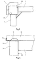
- the corner assembly allows to connect a first frame tube 1, a second frame tube 2 and a foot tube 3 by means of a connecting piece 4, the tubes having rectangular sections.
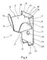
- the connecting piece 4, shown in Figure 6, is a piece made by cutting and folding a metal sheet. It includes an upper plate 5, of generally square shape delimited by 4 main edges, 2 external edges 6 and 7, 2 internal edges 8 and 9.
- the upper plate 5 is folded up along its upper edge 6 to form a first stopper 10.
- the upper plate 5 is folded up along its outer edge 7 to form a second stopper 11.
- the stops 10 and 11 are perpendicular one relative to each other, and define a wedge structure for blocking an angle of the cutting plate 12, shown in Figures 1 and 4 in phantom. Opposite the tabs 10 and 11, the upper plate 5 is connected according to the junction zone 40 to a shelf 13 delimited by an oblique internal edge 14 and two sides of the shelf 15 and 16.
- the side of the shelf 15 is perpendicular to the inner edge 8 of the upper plate 5.
- the shelf side 16 is perpendicular to the inner edge 9 of the upper plate 5.
- the inner edge 8 and the corresponding shelf side 15 define a first cut at right angles 17.
- the inner edge 9 and the side of corresponding shelf 16 define a second cut at right angles 18.
- the upper shelf 13 is connected, by the oblique internal edge 14, to an oblique vertical assembly wall 19, of substantially rectangular shape, and limited by 2 vertical edges 20 and 21.
- the lower edge 22 of the assembly wall 19 is folded back to form a lower flat surface 23.
- the assembly wall 19 is pierced with assembly holes, for example a hole 24, or two holes 24 and 25.
- the connecting piece 4 is intended to be secured to 2 adjacent frame tubes 1 and 2 each having a rectangular section.
- the ends of the framing tubes are cut at right angles, as shown in the figures.
- Framing tubes such as tube 1 have a width L1 less than the length of the inner edge 8 of the upper plate 5.
- the assembly wall 19 preferably has a height equal to the height of the framing tubes such as the tube 1.
- the vertical edge 20 of the assembly wall 19 is in abutment against the interior wall 30 of the framing tube 1, and the lower flap 23 also has an edge in abutment against the same wall 30 of the framing tube.
- the connecting piece 4 is then secured to the framing tube 1 by welding along the anterior edge 27 of the tube, along the side 15 of the shelf, along the vertical edge 20 of the assembly wall 19, and along the lower flap side 23.
- the framing tube 2 is similarly secured by welding it along the inner edge 9, along the side 16 of the shelf, along the vertical edge 21, and along the second side of the lower flap 23. It is found that such an assembly is particularly rigid and resistant, while having relatively short weld lengths, the welds can be carried out under good access conditions.
- the right angle cutouts 17 and 18 are spaced from each other by a distance D, or width of the junction area 40, defining a spacing between the inner edges 31 and 32 of the two tubes of frame 1 and 2. This spacing allows the passage of screws in the holes 24 and 25 as will be explained below. This spacing also allows the junction between the shelf 13 and the upper plate 5.
- the foot tube 3 advantageously has a square section, the sides of which have a length L2 greater than the width L1 of the framing tubes. In this way, the foot tube 3 defines two flat bearing surfaces 33 and 34 intended to come to bear against the right-angled ends of the framing tubes 1 and 2, and to completely close them. This arrangement avoids the appearance of gaps between the ends of the frame tubes 1 and 2 and the foot tube 3.
- the upper end of the foot tube 3 is cut at a right angle. During assembly, it comes to bear under the underside of the upper plate 5 of the connecting piece 4, while the bearing surfaces 33 and 34 of the foot tube 3 bear against the respective ends of the tubes 1 and 2.
- the foot tube 3 is closed at its upper end by a nozzle having a part 36 penetrating inside the foot tube.
- the penetrating part 36 shown in FIG. 5, includes threaded bores such as the bore 35, arranged in correspondence with the holes such as the hole 25 of the assembly plate 19.
- the penetrating part 36 also comprises two rectangular walls 37 and 38 coming to bear against the internal faces of the two support walls 33 and 34 of the foot tube 3. The walls 37 and 38 stiffen the walls 33 and 34 of the tube, and contribute to supporting the effort of holding the ends of the framing tubes 1 and 2.
- the penetrating part 36 of the end piece also allows the assembly and securing of the foot tube 3 on the connecting piece 4, by insertion of screws such as the screw 39 in the holes 25 of the assembly wall 19 and in the bores 35 of the penetrating part 36 of the nozzle. Corresponding holes are provided for this in the walls of the foot tube 3, as shown in the figures.
- the oblique tightening force of the screw 39 strongly applies the bearing surfaces 33 and 34 of the foot tube against the ends of the frame tubes.
- Such tightening substantially contributes to stiffening the assembly and preventing the appearance of gaps between the foot tube and the frame tubes.
- the user is naturally encouraged, by the conformation of the assembly of the present invention, to sufficiently tighten the screw 39 during the adaptation of the foot tube 3 on a corner of the frame, until avoiding any oscillation of the foot tube relative to the frame.
- the forces balance themselves between the support walls 33 and 34 and the corresponding ends of the framing tubes 1 and 2.
- the fact that the support walls 33 and 34 substantially planar bear against the hollow ends of the frame tubes tends to slightly deform the support walls 33 and 34 and to produce a particularly rigid assembly.
- corner assemblies for tubes of non-rectangular section, for example tubes of round section.
- the lateral edges 20 and 21 of the oblique assembly wall must then be shaped into ellipses, to adapt to the interior faces of the framing tubes.
- the edges of the upper shelf 13 and the upper plate 5 adjacent to the framing tubes must also have a shape adapted to the junction zone.
- the ends of the round section framing tubes are also cut at right angles, and come to bear against the flat lateral faces of the square section foot tube.
- the ends of the framing tubes can advantageously be hollowed out to adapt to the lateral face of the foot tube.
Landscapes
- Engineering & Computer Science (AREA)
- General Engineering & Computer Science (AREA)
- Mechanical Engineering (AREA)
- Furniture Connections (AREA)
- Assembled Shelves (AREA)
Applications Claiming Priority (2)
| Application Number | Priority Date | Filing Date | Title |
|---|---|---|---|
| FR8804482A FR2629533B1 (fr) | 1988-03-29 | 1988-03-29 | Assemblage de coin pour table de decoupe |
| FR8804482 | 1988-03-29 |
Publications (2)
| Publication Number | Publication Date |
|---|---|
| EP0335810A1 true EP0335810A1 (de) | 1989-10-04 |
| EP0335810B1 EP0335810B1 (de) | 1991-05-08 |
Family
ID=9364972
Family Applications (1)
| Application Number | Title | Priority Date | Filing Date |
|---|---|---|---|
| EP89420112A Expired - Lifetime EP0335810B1 (de) | 1988-03-29 | 1989-03-29 | Eckverbindung für einen Schneidtisch |
Country Status (4)
| Country | Link |
|---|---|
| EP (1) | EP0335810B1 (de) |
| DE (1) | DE68900078D1 (de) |
| ES (1) | ES2011594B3 (de) |
| FR (1) | FR2629533B1 (de) |
Citations (5)
| Publication number | Priority date | Publication date | Assignee | Title |
|---|---|---|---|---|
| GB1010864A (en) * | 1963-10-23 | 1965-11-24 | Abbott Bros Southall Ltd | Improvements in or relating to furniture construction |
| FR2267067A1 (en) * | 1974-04-12 | 1975-11-07 | Bezborodko Jacques | Tubular frame for table or shelves - has corner assemblies joined by junction pieces |
| US3964404A (en) * | 1975-05-09 | 1976-06-22 | American Hospital Supply Corporation | Shelf and corner post assembly |
| US3981251A (en) * | 1974-10-11 | 1976-09-21 | A/S Raaco Storage Systems | Arrangement at corner joints in a knock-down shelving unit |
| FR2579074A3 (fr) * | 1985-03-19 | 1986-09-26 | Bertho Pierre | Table a deballer, decouper des pieces de viande emballees et permettant de recuperer les dechets |
-
1988
- 1988-03-29 FR FR8804482A patent/FR2629533B1/fr not_active Expired - Fee Related
-
1989
- 1989-03-29 EP EP89420112A patent/EP0335810B1/de not_active Expired - Lifetime
- 1989-03-29 ES ES89420112T patent/ES2011594B3/es not_active Expired - Lifetime
- 1989-03-29 DE DE8989420112T patent/DE68900078D1/de not_active Expired - Fee Related
Patent Citations (5)
| Publication number | Priority date | Publication date | Assignee | Title |
|---|---|---|---|---|
| GB1010864A (en) * | 1963-10-23 | 1965-11-24 | Abbott Bros Southall Ltd | Improvements in or relating to furniture construction |
| FR2267067A1 (en) * | 1974-04-12 | 1975-11-07 | Bezborodko Jacques | Tubular frame for table or shelves - has corner assemblies joined by junction pieces |
| US3981251A (en) * | 1974-10-11 | 1976-09-21 | A/S Raaco Storage Systems | Arrangement at corner joints in a knock-down shelving unit |
| US3964404A (en) * | 1975-05-09 | 1976-06-22 | American Hospital Supply Corporation | Shelf and corner post assembly |
| FR2579074A3 (fr) * | 1985-03-19 | 1986-09-26 | Bertho Pierre | Table a deballer, decouper des pieces de viande emballees et permettant de recuperer les dechets |
Also Published As
| Publication number | Publication date |
|---|---|
| ES2011594A4 (es) | 1990-02-01 |
| EP0335810B1 (de) | 1991-05-08 |
| FR2629533B1 (fr) | 1990-06-29 |
| ES2011594B3 (es) | 1992-01-01 |
| FR2629533A1 (fr) | 1989-10-06 |
| DE68900078D1 (de) | 1991-06-13 |
Similar Documents
| Publication | Publication Date | Title |
|---|---|---|
| EP0725464B1 (de) | Sockel für einen Schaltschrank oder dergleichen und Schrank mit einen solchen Sockel | |
| EP1312283B1 (de) | Stapelbare Liege und Eckstückteil für so eine Liege | |
| EP0106734A1 (de) | Gerüstbildende Vorrichtung für ein Möbelstück zum Einräumen, beispielsweise ein Regal | |
| EP0451012A1 (de) | Regalsystem mit abnehmbaren Ablagen | |
| CA1050489A (fr) | Dispositif d'assemblage entre montants et traverses pour l'execution de structures metalliques | |
| EP0335810B1 (de) | Eckverbindung für einen Schneidtisch | |
| EP1201129B1 (de) | Kochformeneinheit für Nahrugsmitteln | |
| FR2669004A1 (fr) | Ensemble forme par un cadre et une pluralite de recipients destines a contenir des produits alimentaires pendant leur cuisson. | |
| FR2788942A1 (fr) | Structure rigide, notamment une structure formant outil de cuisson industrielle d'aliments. | |
| EP0738485B1 (de) | Anpassungsfähige modulare Regale | |
| FR2659062A1 (fr) | Emballage pour le conditionnement de produits notamment alimentaires et procede de montage d'un tel emballage. | |
| FR2574710A1 (fr) | Classeur | |
| EP0100279B1 (de) | Verfahren zum Fertigen eines Schrankes oder dergleichen aus steifem Blattförmigem Material, Zuschnitt zum Durchführen dieses Verfahrens, sowie auf diese Weise hergestelltes Produkt | |
| FR2458701A1 (fr) | Ferrure d'assemblage d'elements constitutifs de meubles tels que lits et sieges | |
| FR2903669A3 (fr) | 02isse demontable. | |
| EP0647419B1 (de) | Metallischer Tisch mit angesetzten Eckteilen | |
| FR2797937A1 (fr) | Support pour le soutien en hauteur d'un objet | |
| FR2689380A1 (fr) | Meuble, notamment à usage de bureau, à deux plateaux jointifs. | |
| FR2751615A1 (fr) | Plateau et flan en matiere en feuille de carton | |
| BE904965A (fr) | Stand d'exposition. | |
| FR2628615A1 (fr) | Element de mobilier a etageres ou plateaux superposes | |
| FR2525990A1 (fr) | Emballage en carton muni de renforts | |
| FR2736691A1 (fr) | Assemblage de toles, en particulier pour meubles metalliques | |
| FR2590139A1 (fr) | Structure de meuble ainsi que les meubles obtenus par cette structure | |
| FR2884495A1 (fr) | Element presentoir pour l'exposition a la vente de produits, et emballage obtenu par l'imbrication de tels elements presentoirs |
Legal Events
| Date | Code | Title | Description |
|---|---|---|---|
| PUAI | Public reference made under article 153(3) epc to a published international application that has entered the european phase |
Free format text: ORIGINAL CODE: 0009012 |
|
| AK | Designated contracting states |
Kind code of ref document: A1 Designated state(s): BE DE ES FR GB IT |
|
| ITCL | It: translation for ep claims filed |
Representative=s name: MODIANO & ASSOCIATI S.R.L. |
|
| 17P | Request for examination filed |
Effective date: 19891218 |
|
| 17Q | First examination report despatched |
Effective date: 19900822 |
|
| GRAA | (expected) grant |
Free format text: ORIGINAL CODE: 0009210 |
|
| AK | Designated contracting states |
Kind code of ref document: B1 Designated state(s): BE DE ES FR GB IT |
|
| PG25 | Lapsed in a contracting state [announced via postgrant information from national office to epo] |
Ref country code: IT Free format text: LAPSE BECAUSE OF FAILURE TO SUBMIT A TRANSLATION OF THE DESCRIPTION OR TO PAY THE FEE WITHIN THE PRE;WARNING: LAPSES OF ITALIAN PATENTS WITH EFFECTIVE DATE BEFORE 2007 MAY HAVE OCCURRED AT ANY TIME BEFORE 2007. THE CORRECT EFFECTIVE DATE MAY BE DIFFERENT FROM THE ONE RECORDED.SCRIBED TIME-LIMIT Effective date: 19910508 Ref country code: GB Effective date: 19910508 |
|
| REF | Corresponds to: |
Ref document number: 68900078 Country of ref document: DE Date of ref document: 19910613 |
|
| GBV | Gb: ep patent (uk) treated as always having been void in accordance with gb section 77(7)/1977 [no translation filed] | ||
| PLBE | No opposition filed within time limit |
Free format text: ORIGINAL CODE: 0009261 |
|
| STAA | Information on the status of an ep patent application or granted ep patent |
Free format text: STATUS: NO OPPOSITION FILED WITHIN TIME LIMIT |
|
| 26N | No opposition filed | ||
| RAP2 | Party data changed (patent owner data changed or rights of a patent transferred) |
Owner name: TOURNUS EQUIPEMENT SA |
|
| PG25 | Lapsed in a contracting state [announced via postgrant information from national office to epo] |
Ref country code: DE Effective date: 19921201 |
|
| REG | Reference to a national code |
Ref country code: ES Ref legal event code: PC2A Owner name: TOURNUS EQUIPEMENT, S.A. |
|
| PGFP | Annual fee paid to national office [announced via postgrant information from national office to epo] |
Ref country code: BE Payment date: 20000125 Year of fee payment: 12 |
|
| PGFP | Annual fee paid to national office [announced via postgrant information from national office to epo] |
Ref country code: ES Payment date: 20000317 Year of fee payment: 12 Ref country code: FR Payment date: 20000317 Year of fee payment: 12 |
|
| PG25 | Lapsed in a contracting state [announced via postgrant information from national office to epo] |
Ref country code: ES Free format text: LAPSE BECAUSE OF NON-PAYMENT OF DUE FEES Effective date: 20010330 |
|
| PG25 | Lapsed in a contracting state [announced via postgrant information from national office to epo] |
Ref country code: BE Free format text: LAPSE BECAUSE OF NON-PAYMENT OF DUE FEES Effective date: 20010331 |
|
| BERE | Be: lapsed |
Owner name: S.A. TOURNUS EQUIPEMENT Effective date: 20010331 |
|
| PG25 | Lapsed in a contracting state [announced via postgrant information from national office to epo] |
Ref country code: FR Free format text: LAPSE BECAUSE OF NON-PAYMENT OF DUE FEES Effective date: 20011130 |
|
| REG | Reference to a national code |
Ref country code: FR Ref legal event code: ST |
|
| REG | Reference to a national code |
Ref country code: ES Ref legal event code: FD2A Effective date: 20030203 |