EP0335809B1 - Electromechanical torque wrench - Google Patents
Electromechanical torque wrench Download PDFInfo
- Publication number
- EP0335809B1 EP0335809B1 EP19890420110 EP89420110A EP0335809B1 EP 0335809 B1 EP0335809 B1 EP 0335809B1 EP 19890420110 EP19890420110 EP 19890420110 EP 89420110 A EP89420110 A EP 89420110A EP 0335809 B1 EP0335809 B1 EP 0335809B1
- Authority
- EP
- European Patent Office
- Prior art keywords
- cursor
- hand
- alarm
- rigid
- bar
- Prior art date
- Legal status (The legal status is an assumption and is not a legal conclusion. Google has not performed a legal analysis and makes no representation as to the accuracy of the status listed.)
- Expired - Lifetime
Links
Images

Classifications
-
- B—PERFORMING OPERATIONS; TRANSPORTING
- B25—HAND TOOLS; PORTABLE POWER-DRIVEN TOOLS; MANIPULATORS
- B25B—TOOLS OR BENCH DEVICES NOT OTHERWISE PROVIDED FOR, FOR FASTENING, CONNECTING, DISENGAGING OR HOLDING
- B25B23/00—Details of, or accessories for, spanners, wrenches, screwdrivers
- B25B23/14—Arrangement of torque limiters or torque indicators in wrenches or screwdrivers
- B25B23/142—Arrangement of torque limiters or torque indicators in wrenches or screwdrivers specially adapted for hand operated wrenches or screwdrivers
- B25B23/1422—Arrangement of torque limiters or torque indicators in wrenches or screwdrivers specially adapted for hand operated wrenches or screwdrivers torque indicators or adjustable torque limiters
- B25B23/1427—Arrangement of torque limiters or torque indicators in wrenches or screwdrivers specially adapted for hand operated wrenches or screwdrivers torque indicators or adjustable torque limiters by mechanical means
-
- B—PERFORMING OPERATIONS; TRANSPORTING
- B25—HAND TOOLS; PORTABLE POWER-DRIVEN TOOLS; MANIPULATORS
- B25B—TOOLS OR BENCH DEVICES NOT OTHERWISE PROVIDED FOR, FOR FASTENING, CONNECTING, DISENGAGING OR HOLDING
- B25B23/00—Details of, or accessories for, spanners, wrenches, screwdrivers
- B25B23/14—Arrangement of torque limiters or torque indicators in wrenches or screwdrivers
- B25B23/142—Arrangement of torque limiters or torque indicators in wrenches or screwdrivers specially adapted for hand operated wrenches or screwdrivers
- B25B23/1422—Arrangement of torque limiters or torque indicators in wrenches or screwdrivers specially adapted for hand operated wrenches or screwdrivers torque indicators or adjustable torque limiters
- B25B23/1425—Arrangement of torque limiters or torque indicators in wrenches or screwdrivers specially adapted for hand operated wrenches or screwdrivers torque indicators or adjustable torque limiters by electrical means
Definitions
- the invention relates to torque wrenches comprising a tubular body, a bending bar secured to a drive head, articulated at the anterior end of the body and bearing on the posterior end thereof, and means detecting the torque measured from the differential of the arrows of the bending bar and of the body and comprising a cursor which, movable on the body, is integral with a sloping bearing facing the central zone of deformation of the bar bending.
- the object of the present invention is to provide a torque wrench requiring reduced execution precision, while making it possible to obtain the measurement precision sought for each key.
- This key is of the type comprising, as described above, a tubular body, a bending bar secured to the drive head, articulated at the anterior end of the body and bearing on the posterior end thereof, and means detecting the torque measured from the deflection differential between the bending bar and the body, means composed, on the one hand, of two electrical contacts, respectively, of pre-alarm, and of alarm for obtaining the torque displayed, and on the other hand, a contact surface, sloping and connected to a torque setting cursor, movable on the tubular body.
- the end of the flexion bar is linked to the body by a transverse axis, but with the possibility of longitudinal translation, while, on the one hand, the contact surface is produced by machining on a strip spaced from the cursor to which it is linked by studs which, passing through a longitudinal lumen of the body and bearing by a nut on this body, constitute adjustment members for adjusting, one and the other, respectively, the low point and the high point of the measuring scale, and that on the other hand the two electrical contacts are arranged on the bending bar and in the area thereof presenting , in flexion, the largest arrow.
- the components of the key are produced with current manufacturing tolerances of the order of 0.1 mm.
- the setting its calibration is carried out by bringing the cursor to its position corresponding to the low point of the scale and by actuating the adjustment nut concerned until the steep contact surface actuates the contact triggering the obtaining alarm of the couple.
- the cursor is moved on the movable body to its position corresponding to the maximum of the measurement scale and the calibration of the key is adjusted by screwing or unscrewing the other adjustment nut, until 'that the torque obtaining alarm is triggered.
- this last adjustment, and possibly the two adjustments if the measurement scale does not start from a zero value, are carried out on a measurement bench making it possible to communicate to the key, a reaction torque corresponding to the tightening torque. displayed by the cursor.
- the head of each of the adjustment studs is integral with the strip and the nut screwed onto each of these studs is applied, by a play take-up spring, interposed between the strip and the body, on a friction plate, itself applied to the only machined outer face of the body.
- the machined contact face of the inclined strip occupies an immutable position relative to the machined face of the body, whatever the position of the cursor on this body. It follows that the measurement scale is linear and that, after adjusting the extreme values of this scale, the measurement precision is constant, whatever the position of the cursor and the functional clearances specific to each key.
- the tubular body 2 designates the tubular body of the wrench, 3 the bending bar, 4 the drive head for removable clamping sleeves, 5 the slider for adjusting the value of the measured torque.
- the tubular body 2 has, in cross section, an ovoid shape. At its rear end, it has knock-outs 6 constituting notches for positioning the fingers of the hand. Finally, it has two windows 7 laterally, the usefulness of which will be specified below. Over a part of its length, this body is provided with a longitudinal slot 8 bordered by a machined bearing face 9 and in particular rectified to have good flatness.
- the connection of the end of the rod with the axis 12 is ensured by an oblong opening light 13 so as to allow the rod, a longitudinal displacement.
- the light 13 is replaced by a circular bore whose only manufacturing tolerances allow sufficient play with the axis 12.
- the slider 5 is composed of a plate 14 in frictional contact with the rectified face 9 of the body, of an inclined strip 15, arranged in the body, and of two studs 16 ensuring the connection of the plate 14 with the strip 15.
- the head of each of the studs 16 is made integral with the strip 15 by gluing or the like. Its threaded free end passes through the friction plate 14 to receive a nut 17.
- a spring 18, disposed around each stud 16 is interposed between the strip 15 and the body 2 to separate the strip of the body and thus ensure the automatic adjustment of the games.
- this spring bears on an intermediate piece 19 which, disposed inside the body, has a cross section similar to the upper half of this body and laterally includes graduations 20 formalizing the measurement scale and cooperating with a index finger 22 disposed in the lumen 7 of this body.
- the pre-alarm means indicating that the displayed torque is approaching, as well as the alarm means indicating that the displayed torque is reached, are constituted by electrical contacts associated with a dry battery 23 disposed in the posterior end of the tubular body 2.
- each contact is composed of an insulating well 29 with insulating bottom 30 in which is placed a contact ball 32 held in the extended position by a spring 33.
- the protrusion of the ball is limited by a projection provided at the upper end of the insulating well 29.
- the ball of each contact is electrically connected to the corresponding light-emitting diode 26 or 27 connected, moreover, by a common electrical connection 31, to the positive terminal of the battery 23.
- the other terminal of this battery is connected by an elastic tongue 11 to the body 2, and therefore by the cursor 5 to the strip 15.
- the value of the projection of the contacts 24 and 25 is identical since, by the inclination of the sloping contact face 15a of the strip 15, the space between each of the contacts and the face 15a is different, and the first contact that can be actuated is that 25 corresponding to the pre-alarm.
- the light emitting diodes 26a and 27a are carried by the wafer 15. These two diodes are connected directly by a circuit 36 to the positive terminal of the battery 23. In addition, each of 'they are electrically connected by a circuit respectively, 38 and 39 to two conductive tracks, respectively, 38a and 39a, formed on the bearing face 15a of an insulating plate 15b attached to the 15 opposite two contacts 24a- 25a.
- the alarm diode 27a is connected by a circuit 37 to the audible alarm 28.
- a circuit 42 connects the negative terminal of the battery and the axis 12, and, consequently, this terminal with the bending bar 3 and the contacts 24a and 25a embedded in this bar. As shown in more detail in FIG.
- each of the two contacts 24a and 25a, arranged side by side and transversely in conductive wells of the bending bar 3, is composed of a key 40 subjected to the action of a spring 41 tending to project it outwards.
- the key 40 of the contact 25a corresponding to the pre-alarm exceeds the flexion bar 3 more than the key 40 of the contact 24a corresponding to the alarm.
- the friction plate 14 with the nuts 17 is protected by a glued cover 44 also constituting the actuator of the cursor and the member preventing access to the nuts.
- this cover has openings for the passage of light emitting diodes 26a-27a.
- the two extreme values of its measurement scale are adjusted.
- This adjustment has two phases. A first phase consisting in adjusting the low point of the scale corresponding to a zero value and, more generally, in a value of a few meters-kilograms and a second phase consisting in adjusting the high point of the scale.
- This adjustment is made on a measuring bench allowing communicate to the drive head of the key and consequently to the whole of the key, a reaction torque of defined but adjustable value, corresponding to the value of the torque displayed on the key, by the cursor 5 and visible on the gradation 20 through one of the windows 7.
- the adjustment of the low point of the measurement scale is therefore carried out by exerting on the drive head 4 a reaction torque corresponding to the value of the low point of the scale and by bringing the cursor 5, including the cover 44 has been removed, in the position where the scale value of the gradation coincides with the index 22 of the body.
- the strip 15 is moved transversely in the direction of the bar 3 until it comes into contact first with the pre-contact. alarm, 25 or 25a, then with the alarm contact 24 or 24a, which causes the corresponding light-emitting diode to light up and the horn 28 to operate.
- the cursor 5 is moved to the other end of the measurement scale, i.e. until the mark 22 on the body 2 coincides with the maximum value of the graduation 20 carried by the part 19.
- the nut 17 of the stud 16 disposed at the front end of the plate 14 is actuated until the strip 15 meets the contact 24 or 24a alarm. This operation finished, the cover 44 is put in place and glued to oppose any misadjustments.
- At least one of the studs 16 is disposed on the strip 15 so as to come above the alarm contact 24 or 24a when the cursor 5 is in a position corresponding to the coincidence with the index 22 of one of the extreme values of the measurement scale. In the embodiments, this superposition takes place when the index coincides with the bottom of scale value. This particular arrangement avoids any deterioration of the adjustment made for this bottom of scale value, when the alarm and tilting of the strip 15 for the high value of the measurement scale are adjusted.
- the adjustment of the strip for the high value of the measurement scale, adjustment being effected by actuation of the nut 17 of the front screw 16, causes a modification of the inclination of this strip relative to the general longitudinal axis of the key and a pivoting of this strip around the other stud, without any modification of the length adjustment made on the first stud.
- Such an arrangement of at least one of the studs therefore facilitates adjustment.
- the adjustment operation on a measurement bench also makes it possible, after adjusting the two extreme values, to check the operation of the key for all or part of the intermediate values shown on the scale 20.
- the plate 15 carrying the contact surface 15a is inclined so as to approach the bending bar 3 going towards the rear end of this bar. If the same results can be obtained with a reverse inclination of the insert, the arrangement presented is more advantageous because, when using the key for tightening with high torques, the cursor is moved towards the rear end of the key, that is to say on the zone which is less sensitive to possible deformations of the tubular body 2. In other words and although the moment of inertia of the tubular body is much greater than the moment of inertia of the bending bar 3, the inclination of the plate, retained in the embodiments shown, eliminates any risk of alteration of the measurement by possible deformations of the tubular body.
- the body 2 comprises, at the rear end of the bar 3, a cradle 43 visible in FIGS. 2 and 4.
- the contacts 24-25 and 24a-25a can indifferently be constituted by a ball 32 or by a pusher 40 provided that their electrical connections with the diodes and the body remain the same.
Description
L'invention est relative aux clés dynamométriques comportant un corps tubulaire, une barre de flexion solidaire d'une tête d'entrainement, articulée à l'extrémité antérieure du corps et en appui sur l'extrémité postérieure de celui-ci, et des moyens détectant le couple mesuré à partir du différentiel des flèches de la barre de flexion et du corps et comprenant un curseur qui, mobile sur le corps, est solidaire d'une portée en pente faisant vis à vis à la zone centrale de déformation de la barre de flexion.The invention relates to torque wrenches comprising a tubular body, a bending bar secured to a drive head, articulated at the anterior end of the body and bearing on the posterior end thereof, and means detecting the torque measured from the differential of the arrows of the bending bar and of the body and comprising a cursor which, movable on the body, is integral with a sloping bearing facing the central zone of deformation of the bar bending.
Un dispositif de ce type est décrit dans le brevet français 2131018 concernant une clé dynamométrique à déclenchement, c'est à dire informant l'opérateur de l'obtention du couple au moyen d'une émission sonore. Dans cette clé, la portée en pente est constituée par la face inférieure d'un coin, fixée sur le corps avec possibilité de translation horizontale mais sans réglage vertical. En raison de ce montage, et de l'absence de toute possibilité de réglage, la précision de la clé dépend, indépendamment des aléas du serrage, de la précision de fabrication et de montage de ses composants.A device of this type is described in French patent 2131018 concerning a triggered torque wrench, that is to say informing the operator of obtaining the torque by means of a sound emission. In this key, the sloping span consists of the underside of a corner, fixed to the body with the possibility of horizontal translation but without vertical adjustment. Because of this assembly, and the absence of any possibility of adjustment, the precision of the key depends, independently of the vagaries of tightening, the precision of manufacture and assembly of its components.
Il faut d'ailleurs rappeler que, dans une clé de ce type, c'est à dire dans laquelle on mesure la flèche d'une barre de flexion quasi encastrée à l'une de ses extrémités et en appui par son autre extrémité, la valeur de cette flèche est fonction de la valeur entre appui affectée d'une puissance 3 et du diamètre de cette barre affectée d'une puissance 4. Il en résulte que, pour obtenir des résultats fiables, d'une clé à une autre, les tolérances de fabrication de la barre, du corps, mais aussi de leur liaison, doivent être très serrées, de l'ordre de 0,01 mm, ce qui intervient de manière sensible sur le prix de la clé. En pratique, de telles clés à déclenchement ont une précision relativement faible, et aléatoire d'une clé à une autre.It should also be remembered that, in a key of this type, that is to say in which the deflection of a flexion bar is almost embedded at one of its ends and supported by its other end, the value of this arrow is a function of the value between pressing assigned with a
On connait par ailleurs, par le brevet U.S. 2250941, une clé dynamométrique dans laquelle l'indication de l'approche et l'indication de l'obtention de la valeur du couple de serrage, sont assurées par deux contacts électriques qui, intervenant sur des moyens lumineux et sonores, sont séparés d'une face de la barre de flexion par des intervalles différents. Dans ce dispositif, les contacts ont une position fixe et le réglage du tarage de la mesure s'effectue par déplacement du point d'encastrement postérieur de la barre de flexion, articulé par son extrémité antérieure sur le corps. En raison de sa structure et, notamment du montage des contacts électriques, mais aussi des moyens de réglage du tarage de la mesure, la précision de mesure de cette clé dépend, comme dans le cas précédent, de la précision d'exécution et d'assemblage de ses composants.We also know, from US patent 2250941, a torque wrench in which the indication of the approach and the indication of obtaining the value of the tightening torque, are provided by two electrical contacts which, acting on light and sound means are separated from one side of the bending bar by different intervals. In this device, the contacts have a fixed position and the adjustment of the calibration of the measurement is carried out by displacement of the rear embedding point of the bending bar, articulated by its front end on the body. Because of its structure and, in particular the mounting of the electrical contacts, but also of the means for adjusting the calibration of the measurement, the measurement accuracy of this key depends, as in the previous case, on the execution precision and assembly of its components.
La présente invention a pour but de fournir une clé dynamométrique exigeant une précision d'exécution réduite, tout en permettant d'obtenir la précision de mesure recherchée pour chaque clé.The object of the present invention is to provide a torque wrench requiring reduced execution precision, while making it possible to obtain the measurement precision sought for each key.
Cette clé est du type comportant, comme décrit ci dessus, un corps tubulaire, une barre de flexion solidaire de la tête d'entrainement, articulée à l'extrémité antérieure du corps et en appui sur l'extrémité postérieure de celui-ci, et des moyens détectant le couple mesuré à partir du différentiel de flèche entre la barre de flexion et le corps, moyens composés, d'une part, de deux contacts électriques,respectivement, de pré-alarme, et d'alarme d'obtention du couple affiché, et d'autre part, d'une portée de contact, pentue et reliée à un curseur de tarage du couple, mobile sur le corps tubulaire.This key is of the type comprising, as described above, a tubular body, a bending bar secured to the drive head, articulated at the anterior end of the body and bearing on the posterior end thereof, and means detecting the torque measured from the deflection differential between the bending bar and the body, means composed, on the one hand, of two electrical contacts, respectively, of pre-alarm, and of alarm for obtaining the torque displayed, and on the other hand, a contact surface, sloping and connected to a torque setting cursor, movable on the tubular body.
A cet effet, dans cette clé du type précitée, l'extrémité de la barre de flexion, opposée à celle solidaire de la tête d'entrainement, est liée au corps par un axe transversal, mais avec possibilité de translation longitudinale, tandis que, d'une part la portée de contact est réalisée par usinage sur une réglette espacée du curseur auquel elle est liée par des goujons qui, traversant une lumière longitudinale du corps et prenant appui par un écrou sur ce corps, constituent organes de réglage pour ajuster, l'un et l'autre, respectivement, le point bas et le point haut de l'échelle de mesure, et que d'autre part les deux contacts électriques sont disposés sur la barre de flexion et dans la zone de celle-ci présentant, en flexion, la plus grande flèche.To this end, in this key of the aforementioned type, the end of the flexion bar, opposite to that secured to the drive head, is linked to the body by a transverse axis, but with the possibility of longitudinal translation, while, on the one hand, the contact surface is produced by machining on a strip spaced from the cursor to which it is linked by studs which, passing through a longitudinal lumen of the body and bearing by a nut on this body, constitute adjustment members for adjusting, one and the other, respectively, the low point and the high point of the measuring scale, and that on the other hand the two electrical contacts are arranged on the bending bar and in the area thereof presenting , in flexion, the largest arrow.
Grâce à cet agencement, les composants de la clé sont réalisés avec des tolérances de fabrication courante de l'ordre de 0,1 mm. Lorsque tous les composants de la clé sont assemblés, le réglage de son tarage s'effectue en amenant le curseur à sa position correspondant au point bas de l'échelle et en actionnant l'écrou de réglage concerné jusqu'à ce que la portée de contact pentue actionne le contact enclenchant l'alarme d'obtention du couple. Ce premier réglage effectué, le curseur est déplacé sur le corps mobile jusqu'à sa position correspondant au maximum de l'échelle de mesure et il est procédé au réglage du tarage de la clé en vissant ou dévissant l'autre écrou de réglage, jusqu'à ce que s'enclenche l'alarme d'obtention du couple. Bien entendu, ce dernier réglage, et éventuellement les deux réglages si l'échelle de mesure ne part pas d'une valeur zéro, sont effectués sur un banc de mesure permettant de communiquer à la clé, un couple de réaction correspondant au couple de serrage affiché par le curseur.Thanks to this arrangement, the components of the key are produced with current manufacturing tolerances of the order of 0.1 mm. When all the key components are assembled, the setting its calibration is carried out by bringing the cursor to its position corresponding to the low point of the scale and by actuating the adjustment nut concerned until the steep contact surface actuates the contact triggering the obtaining alarm of the couple. Once this first adjustment has been made, the cursor is moved on the movable body to its position corresponding to the maximum of the measurement scale and the calibration of the key is adjusted by screwing or unscrewing the other adjustment nut, until 'that the torque obtaining alarm is triggered. Of course, this last adjustment, and possibly the two adjustments if the measurement scale does not start from a zero value, are carried out on a measurement bench making it possible to communicate to the key, a reaction torque corresponding to the tightening torque. displayed by the cursor.
Un tel réglage, qui est effectué pour chaque clé, permet d'ajuster parfaitement les deux valeurs extrêmes de son échelle de mesure, et cela quelle que soit la précision d'exécution des composants de la clé ou la précision de montage de ses composants. En d'autres termes, cette possibilité de réglage permet, d'une part, d'obtenir une précision certaine pour chacune des clés fabriquées et, d'autre part, d'utiliser pour la fabrication des clés, des composants exigeants une moins grande précision que les clés traditionnelles et donc moins onéreux à réaliser.Such an adjustment, which is carried out for each key, makes it possible to perfectly adjust the two extreme values of its measurement scale, and this regardless of the precision of execution of the components of the key or the precision of assembly of its components. In other words, this possibility of adjustment makes it possible, on the one hand, to obtain a certain precision for each of the keys produced and, on the other hand, to use for the manufacture of the keys, less demanding components. precision than traditional keys and therefore less expensive to produce.
Dans une forme d'exécution de l'invention, la tête de chacune des goujons de réglage est solidaire de la réglette et l'écrou vissé sur chacun de ces goujons est appliqué, par un ressort de rattrapage de jeu, interposé entre la réglette et le corps, sur une plaquette de frottement, elle-même appliquée sur la seule face extérieure usinée du corps.In one embodiment of the invention, the head of each of the adjustment studs is integral with the strip and the nut screwed onto each of these studs is applied, by a play take-up spring, interposed between the strip and the body, on a friction plate, itself applied to the only machined outer face of the body.
Grâce à ce montage, la face de contact usinée de la réglette incliné occupe une position immuable par rapport à la face usinée du corps, quelle que soit la position du curseur sur ce corps. Il en résulte que l'échelle de mesure est linéaire et que, après réglage des valeurs extrêmes de cette échelle, la précision de mesure est constante, quelle que soit la position du curseur et les jeux fonctionnels propres à chaque clé.Thanks to this arrangement, the machined contact face of the inclined strip occupies an immutable position relative to the machined face of the body, whatever the position of the cursor on this body. It follows that the measurement scale is linear and that, after adjusting the extreme values of this scale, the measurement precision is constant, whatever the position of the cursor and the functional clearances specific to each key.
D'autres avantages ressortiront de la description qui suit en référence au dessin schématique annexé représentant, à titre d'exemples non limitatifs, deux formes d'exécution de la clé selon l'invention.
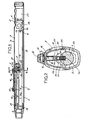
- Figure 1 est une vue en coupe longitudinale d'une première forme d'exécution de la clé,
- Figure 2 en est une vue en coupe suivant II-II de figure 1 montrant, à échelle agrandie, les composants de cette clé,
- Figures 3 et 4 sont des vues similaires aux figures 1 et 2 mais correspondant à une autre forme d'exécution de la clé.
- FIG. 1 is a view in longitudinal section of a first embodiment of the key,
- Figure 2 is a sectional view along II-II of Figure 1 showing, on an enlarged scale, the components of this key,
- Figures 3 and 4 are views similar to Figures 1 and 2 but corresponding to another embodiment of the key.
Dans ces dessins, 2 désigne le corps tubulaire de la clé, 3 la barre de flexion, 4 de la tête d'entrainement de douilles de serrage amovibles, 5 le curseur de réglage de la valeur du couple mesuré. Comme le montrent les figures 2 et 4, le corps tubulaire 2 présente, en section transversale, une forme ovoïde. A son extrémité postérieure, il comporte des défoncements 6 constituant crans de positionnement des doigts de la main. Enfin, il comporte latéralement deux fenêtres 7 dont l'utilité sera précise plus loin. Sur une partie de sa longueur, ce corps est muni d'une fente longitudinale 8 bordée par une face d'appui usinée 9 et notamment rectifiée pour présenter une bonne planéité.In these drawings, 2 designates the tubular body of the wrench, 3 the bending bar, 4 the drive head for removable clamping sleeves, 5 the slider for adjusting the value of the measured torque. As shown in Figures 2 and 4, the tubular body 2 has, in cross section, an ovoid shape. At its rear end, it has knock-
La barre de flexion 3, réalisée dans une barre profilée c'est à dire avec des tolérances diamétrales de l'ordre de 0,1 mm, est encastrée dans la tête d'entrainement 4 et est liée par un axe transversal d'articulation 10, à l'extrémité antérieure du corps tubulaire 2. Son extrémité postérieure est également liée au corps par un axe transversal 12. Dans la forme d'exécution représentée, la liaison de l'extrémité de la tige avec l'axe 12 est assurée par une lumière débouchante oblongue 13 de manière à permettre à la tige, un déplacement longitudinal. En pratique et en raison du faible mouvement de translation de cette extrémité lorsque la barre de flexion est déformée, la lumière 13 est remplacée par un alésage circulaire dont les seules tolérances de fabrication permettent un jeu suffisant avec l'axe 12.The
Dans les deux formes d'exécution, le curseur 5 est composé d'une plaquette 14 en contact de frottement avec la face rectifiée 9 du corps, d'une réglette inclinée 15, disposée dans le corps, et de deux goujons 16 assurant la liaison de la plaquette 14 avec la réglette 15. Comme le montrent plus en détails les figures 2 et 4, la tête de chacun des goujons 16 est rendue solidaire de la réglette 15 par collage ou autre. Son extrémité libre filetée traverse la plaquette de frottement 14 pour recevoir un écrou 17. Par ailleurs, comme le montrent ces figures, un ressort 18, disposé autour de chaque goujon 16, est interposé entre la réglette 15 et le corps 2 pour écarter la réglette du corps et assurer ainsi le rattrapage automatique des jeux. En fait, ce ressort prend appui sur une pièce intermédiaire 19 qui, disposé à l'intérieur du corps, présente une section transversale similaire à la moitié supérieure de ce corps et comporte latéralement des graduations 20 formalisant l'échelle de mesure et coopérant avec un index 22 disposé dans la lumière 7 de ce corps. Enfin, les moyens de pré-alarme, indiquant que l'on approche du couple affiché, de même que les moyens d'alarme indiquant que l'on atteint le couple affiché, sont constitués par des contacts électriques associés à une pile sèche 23 disposée dans l'extrémité postérieure du corps tubulaire 2.In both embodiments, the slider 5 is composed of a
Dans la forme d'exécution représentée aux figures 1 et 2, les deux contacts électriques, respectivement, antérieur d'alarme 24 et postérieur de pré-alarme 25, sont montés sur le circuit d'alimentation de deux diodes électroluminescentes, respectivement 26 et 27, dont celle 26 est reliée par un circuit 34 à un avertisseur sonore 28 connecté à la borne positive de la pile.Comme le montre la figure 2, chaque contact est composé d'un puits isolants 29 avec fond isolant 30 dans lequel est disposée une bille de contact 32 maintenue en position sortie par un ressort 33. Le dépassement de la bille est limité par une saillie ménagée à l'extrémité supérieure du puits isolant 29. La bille de chaque contact est reliée électriquement à la diode luminescente correspondante 26 ou 27 reliée, par ailleurs, par une liaison électrique commune 31, à la borne positive de la pile 23. L'autre borne de cette pile est reliée par une languette élastique 11 au corps 2, et donc par le curseur 5 à la réglette 15.In the embodiment shown in Figures 1 and 2, the two electrical contacts, respectively,
Dans cette forme d'exécution, où les deux contacts sont disposés longitudinalement l'un derrière l'autre et coopèrent avec une face pentue dans le sens longitudinal, la valeur de la saillie des contacts 24 et 25 est identique puisque, par l'inclinaison de la face de contact pentue 15a de la réglette 15, l'espace entre chacun des contacts et la face 15a est différent, et le premier contact pouvant être actionné est celui 25 correspondant à la pré-alarme.In this embodiment, where the two contacts are arranged longitudinally one behind the other and cooperate with a sloping face in the longitudinal direction, the value of the projection of the
Dans la forme d'exécution représentée aux figures 3 et 4, les diodes électroluminescentes 26a et 27a sont portées par la plaquette 15. Ces deux diodes sont reliées directement par un circuit 36 à la borne positive de la pile 23. En outre, chacune d'elles est reliée électriquement par un circuit respectivement, 38 et 39 à deux pistes conductrices, respectivement, 38a et 39a, ménagées sur la face de portée 15a d'une plaquette isolante 15b rapportée sur la 15 en vis à vis de deux contacts 24a-25a. La diode d'alarme 27a est reliée par un circuit 37 à l'alarme sonore 28. Enfin un circuit 42 relie la borne négative de la pile et l'axe 12, et, en conséquence,cette borne avec la barre de flexion 3 et les contacts 24a et 25a noyés dans cette barre. Comme le montre plus en détails la figure 4, chacun des deux contacts 24a et 25a, disposés côte à côte et transversalement dans des puits conducteurs de la barre de flexion 3, est composé d'une touche 40 soumise à l'action d'un ressort 41 tendant à la faire saillir vers l'extérieur. La touche 40 du contact 25a correspondant à la pré-alarme dépasse davantage de la barre de flexion 3 que la touche 40 du contact 24a correspondant à l'alarme.In the embodiment shown in Figures 3 and 4, the
Dans ces deux dispositifs, la plaquette de frottement 14 avec les écrous 17 est protégée par un capot collé 44 constituant, également, organe d'actionnement du curseur et organe d'interdiction d'accès aux écrous. Pour la forme d'exécution représentée à la figure 3, ce capot comporte des ouvertures permettant le passage des diodes électroluminescentes 26a-27a.In these two devices, the
Dans les deux formes d'exécution, lorsque les éléments de la clé sont assemblés, il est procédé au réglage des deux valeurs extrêmes de son échelle de mesure. Ce réglage comprend deux phases. Une première phase consistant à régler le point bas de l'échelle correspondant à une valeur zéro et, plus généralement, à une valeur de quelques mètres-kilogrammes et une deuxième phase consistant à régler le point haut de l'échelle.In the two embodiments, when the elements of the key are assembled, the two extreme values of its measurement scale are adjusted. This adjustment has two phases. A first phase consisting in adjusting the low point of the scale corresponding to a zero value and, more generally, in a value of a few meters-kilograms and a second phase consisting in adjusting the high point of the scale.
Ce réglage est effectué sur un banc de mesure permettant de communiquer à la tête d'entrainement de la clé et en conséquence à l'ensemble de la clé, un couple de réaction de valeur définie mais réglable, correspondant à la valeur du couple affiché sur la clé, par le curseur 5 et visible sur la gradation 20 à travers l'une des fenêtres 7.This adjustment is made on a measuring bench allowing communicate to the drive head of the key and consequently to the whole of the key, a reaction torque of defined but adjustable value, corresponding to the value of the torque displayed on the key, by the cursor 5 and visible on the
Le réglage du point bas de l'échelle de mesure s'effectue donc en exerçant sur la tête d'entrainement 4 un couple de réaction correspondant à la valeur du point bas de l'échelle et en amenant le curseur 5, dont le capot 44 a été enlevé, dans la position où la valeur de bas d'échelle de la gradation coïncide avec l'index 22 du corps. Par actionnement de l'écrou 17 du goujon 16 disposé à l'extrémité postérieure du curseur, la réglette 15 est déplacée transversalement en direction de la barre 3 jusqu'à ce qu'elle vienne en contact d'abord avec le contact de pré-alarme, 25 ou 25a, puis avec le contact d'alarme 24 ou 24a, ce qui entraine l'allumage de la diode électroluminescente correspondante et le fonctionnement de l'avertisseur sonore 28. Dans la deuxième phase du réglage, le curseur 5 est déplacé jusqu'à l'autre extrémité de l'échelle de mesure c'est à dire jusqu'à ce que le repère 22 du corps 2 coincide avec la valeur maximale de la graduation 20 portée par la pièce 19. Après que la clé ait été soumise à un couple de valeur égale à celle du haut de l'échelle de mesure, l'écrou 17 du goujon 16 disposé à l'extrémité antérieure de la plaquette 14 est actionné jusqu'à ce que la réglette 15 rencontre le contact 24 ou 24a d'alarme. Cette opération terminée, le capot 44 est mis en place et collé pour s'opposer à tous déréglages.The adjustment of the low point of the measurement scale is therefore carried out by exerting on the drive head 4 a reaction torque corresponding to the value of the low point of the scale and by bringing the cursor 5, including the
Il faut noter qu'au moins l'un des goujons 16 est disposé sur la réglette 15 de manière à venir au-dessus du contact d'alarme 24 ou 24a lorsque le curseur 5 est dans une position correspondant à la coïncidence avec l'index 22 de l'une des valeurs extrêmes de l'échelle de mesure. Dans les formes d'exécution cette superposition a lieu lorsque l'index coïncide avec la valeur de bas d'échelle. Cette disposition particulière évite toute détérioration du réglage effectué pour cette valeur de bas d'échelle, lorsqu'il est procédé au réglage de l'alarme et de l'inclinaison de la réglette 15 pour la valeur haute de l'échelle de mesure. En effet dans ces conditions, le réglage de la réglette, pour la valeur haute de l'échelle de mesure, réglage s'effectuant par actionnement de l'écrou 17 de la vis antérieure 16, entraine une modification de l'inclinaison de cette réglette par rapport à l'axe longitudinal général de la clé et un pivotement de cette réglette autour de l'autre goujon, sans modification quelconque du réglage de longueur effectué sur le premier goujon. Une telle disposition d'au moins l'un des goujons facilite donc le réglage.It should be noted that at least one of the
L'opération de réglage sur banc de mesure permet aussi, après réglage des deux valeurs extrêmes, de vérifier le fonctionnement de la clé pour tout ou partie des valeurs intermédaires portées sur la graduation 20.The adjustment operation on a measurement bench also makes it possible, after adjusting the two extreme values, to check the operation of the key for all or part of the intermediate values shown on the
Il faut ici remarquer que pour obtenir une linéarité de l'échelle de mesure entre les deux valeurs extrêmes, linéarité permettant d'obtenir la précision recherchée pour toutes les valeurs intermédiaires, il suffit que deux contraintes de fabrication soient respectées, à savoir la planéité de la face 9 sur laquelle coulisse la plaquette 14 et la planéité de la face 15a de la réglette 15. Il faut ici noter que ces contraintes de fabrication sont très faciles à satisfaire et conduisent à une clé beaucoup moins onéreuse à réaliser que les clés actuelles dans lesquelles, pour obtenir une précision de mesure, les tolérances dimensionnelles, de fabrication et de montage de chacun des composants essentiels, sont excessivement serrées.It should be noted here that in order to obtain a linearity of the measurement scale between the two extreme values, linearity making it possible to obtain the desired precision for all the intermediate values, it suffices that two manufacturing constraints are respected, namely the flatness of the
Dans les formes d'exécution décrites, la plaquette 15 portant la portée de contact 15a est inclinée de manière à se rapprocher de la barre de flexion 3 en allant vers l'extrémité postérieure de cette barre. Si les mêmes résultats peuvent être obtenus avec une inclinaison inverse de la plaquette, la disposition présentée s'avère plus intéressante car, lors de l'utilisation de la clé pour un serrage avec des couples élevés, le curseur est déplacé vers l'extrémité postérieure de la clé, c'est à dire sur la zone qui est moins sensible aux éventuelles déformations du corps tubulaire 2. En d'autres termes et bien que le moment d'inertie du corps tubulaire soit très supérieur au moment d'inertie de la barre de flexion 3, l'inclinaison de la plaquette, retenue dans les formes d'exécution représentées, supprime tous risques d'altération de la mesure par d'éventuelles déformations du corps tubulaire.In the embodiments described, the
Enfin, pour éviter tous déplacements latéraux de la barre de flexion pouvant modifier la position des contacts ou altérer la mesure, le corps 2 comporte, au niveau de l'extrémité postérieure de la barre 3, un berceau 43 visible aux figures 2 et 4.Finally, to avoid any lateral displacements of the bending bar which could modify the position of the contacts or alter the measurement, the body 2 comprises, at the rear end of the
Bien entendu, les contacts 24-25 et 24a-25a peuvent indifféremment être constitués par une bille 32 ou par un poussoir 40 pourvu que leurs liaisons électriques avec les diodes et le corps restent les mêmes.Of course, the contacts 24-25 and 24a-25a can indifferently be constituted by a
Claims (7)
Applications Claiming Priority (2)
| Application Number | Priority Date | Filing Date | Title |
|---|---|---|---|
| FR8804638 | 1988-04-01 | ||
| FR8804638A FR2629383B1 (en) | 1988-04-01 | 1988-04-01 | ELECTROMECHANICAL DYNAMOMETRIC KEY |
Publications (2)
| Publication Number | Publication Date |
|---|---|
| EP0335809A1 EP0335809A1 (en) | 1989-10-04 |
| EP0335809B1 true EP0335809B1 (en) | 1991-08-14 |
Family
ID=9365091
Family Applications (1)
| Application Number | Title | Priority Date | Filing Date |
|---|---|---|---|
| EP19890420110 Expired - Lifetime EP0335809B1 (en) | 1988-04-01 | 1989-03-29 | Electromechanical torque wrench |
Country Status (4)
| Country | Link |
|---|---|
| EP (1) | EP0335809B1 (en) |
| DE (1) | DE68900197D1 (en) |
| ES (1) | ES2025851T3 (en) |
| FR (1) | FR2629383B1 (en) |
Families Citing this family (1)
| Publication number | Priority date | Publication date | Assignee | Title |
|---|---|---|---|---|
| FR2736858B1 (en) * | 1995-07-18 | 1997-10-10 | Sam Outillage | ELECTROMECHANICAL DYNAMOMETRIC SCREWDRIVER WITH SOUND AND / OR VISUAL ALARM |
Family Cites Families (8)
| Publication number | Priority date | Publication date | Assignee | Title |
|---|---|---|---|---|
| US2250941A (en) * | 1938-05-21 | 1941-07-29 | Automotive Maintenance Mach Co | Torque measuring wrench |
| US2474247A (en) * | 1944-07-08 | 1949-06-28 | Hattan Mark | Signal type torque indicating wrench |
| US2440683A (en) * | 1944-09-13 | 1948-05-04 | Hattan Mark | Signal type torque indicating wrench |
| US2663209A (en) * | 1949-04-12 | 1953-12-22 | Buckeye Tools Corp | Torque indicating power operated tool |
| FR2131018A5 (en) * | 1971-03-30 | 1972-11-10 | Snap On Tools Corp | |
| US3763724A (en) * | 1971-07-26 | 1973-10-09 | Snap On Tools Corp | Automatic torque release wrench of the preset type |
| DE3026134A1 (en) * | 1980-07-10 | 1982-02-04 | Bayerische Motoren Werke AG, 8000 München | Torque spanner with flexible rod - has tube parallel to rod connected to spanner head and coupled to slider, movable in long direction of rod |
| CA1220367A (en) * | 1983-01-27 | 1987-04-14 | Repco Limited | Torque wrench |
-
1988
- 1988-04-01 FR FR8804638A patent/FR2629383B1/en not_active Expired - Lifetime
-
1989
- 1989-03-29 EP EP19890420110 patent/EP0335809B1/en not_active Expired - Lifetime
- 1989-03-29 ES ES89420110T patent/ES2025851T3/en not_active Expired - Lifetime
- 1989-03-29 DE DE8989420110T patent/DE68900197D1/en not_active Expired - Lifetime
Also Published As
| Publication number | Publication date |
|---|---|
| FR2629383A1 (en) | 1989-10-06 |
| FR2629383B1 (en) | 1991-03-15 |
| EP0335809A1 (en) | 1989-10-04 |
| DE68900197D1 (en) | 1991-09-19 |
| ES2025851T3 (en) | 1992-04-01 |
Similar Documents
| Publication | Publication Date | Title |
|---|---|---|
| WO1995020109A1 (en) | Safer disc brake | |
| FR2695616A1 (en) | Bicycle brake with articulated levers. | |
| CA2127912C (en) | Tool for measuring the tightening force exerted by a length measuring-device mobile arm | |
| EP0074883A1 (en) | Rectilinear translation mechanism with belt pulleys and belts | |
| EP0739595A1 (en) | Fastening level with adjustable hook | |
| EP0335809B1 (en) | Electromechanical torque wrench | |
| FR2491007A1 (en) | VEHICLE LEVEL DETECTOR WITH SECURITY MECHANISM | |
| EP0385945B1 (en) | Ski binding with a sole plate | |
| EP2214066A1 (en) | Correction device for timepiece equipped with two elements for indicating the time | |
| EP0260583A1 (en) | Feeler for measuring dimensions | |
| FR2746957A1 (en) | CONTROL MECHANISM OF A CIRCUIT BREAKER WITH WIDE OPENING ANGLE | |
| EP0192547B1 (en) | Actuating device for a double master brake cylinder | |
| EP0446770B1 (en) | Alarm-clock | |
| EP3423780A1 (en) | Strain sensor with measurement discrimination according to the deformation direction | |
| EP0760524A1 (en) | Device for adjusting a thermal tripping device for a circuit breaker | |
| FR2531895A1 (en) | TIGHTENING WRENCH | |
| FR2584494A1 (en) | MULTIPURPOSE DEVICE FOR CALIBRATING AND CONTROLLING THE TIGHTENING TORQUE OF A SCREW-NUT BINDING MEMBER | |
| FR2633544A1 (en) | Electrical-detection torque wrench | |
| EP1610026B1 (en) | Brake caliper for an electromechanical disc brake | |
| FR2780324A1 (en) | POSITIONING, HOLDING OR TIGHTENING DEVICE | |
| EP0483008B1 (en) | Lenses alignment device with rotating table | |
| FR2506938A1 (en) | Tennis racket string tension measuring device - has body section pressing string face against base portion and determines resultant deflection | |
| EP1069038B1 (en) | Automatic pedal for mountainbike | |
| EP1926573B1 (en) | Torque wrench | |
| FR2661743A1 (en) | Device for checking the tightening force of a screwed assembly |
Legal Events
| Date | Code | Title | Description |
|---|---|---|---|
| PUAI | Public reference made under article 153(3) epc to a published international application that has entered the european phase |
Free format text: ORIGINAL CODE: 0009012 |
|
| 17P | Request for examination filed |
Effective date: 19890403 |
|
| AK | Designated contracting states |
Kind code of ref document: A1 Designated state(s): BE DE ES GB LU NL |
|
| 17Q | First examination report despatched |
Effective date: 19901114 |
|
| GRAA | (expected) grant |
Free format text: ORIGINAL CODE: 0009210 |
|
| AK | Designated contracting states |
Kind code of ref document: B1 Designated state(s): BE DE ES GB LU NL |
|
| REF | Corresponds to: |
Ref document number: 68900197 Country of ref document: DE Date of ref document: 19910919 |
|
| GBT | Gb: translation of ep patent filed (gb section 77(6)(a)/1977) | ||
| REG | Reference to a national code |
Ref country code: ES Ref legal event code: FG2A Ref document number: 2025851 Country of ref document: ES Kind code of ref document: T3 |
|
| PLBE | No opposition filed within time limit |
Free format text: ORIGINAL CODE: 0009261 |
|
| STAA | Information on the status of an ep patent application or granted ep patent |
Free format text: STATUS: NO OPPOSITION FILED WITHIN TIME LIMIT |
|
| 26N | No opposition filed | ||
| EPTA | Lu: last paid annual fee | ||
| PGFP | Annual fee paid to national office [announced via postgrant information from national office to epo] |
Ref country code: NL Payment date: 20000331 Year of fee payment: 12 |
|
| PGFP | Annual fee paid to national office [announced via postgrant information from national office to epo] |
Ref country code: LU Payment date: 20000405 Year of fee payment: 12 |
|
| PGFP | Annual fee paid to national office [announced via postgrant information from national office to epo] |
Ref country code: DE Payment date: 20010315 Year of fee payment: 13 |
|
| PGFP | Annual fee paid to national office [announced via postgrant information from national office to epo] |
Ref country code: GB Payment date: 20010328 Year of fee payment: 13 |
|
| PG25 | Lapsed in a contracting state [announced via postgrant information from national office to epo] |
Ref country code: LU Free format text: LAPSE BECAUSE OF NON-PAYMENT OF DUE FEES Effective date: 20010329 |
|
| PG25 | Lapsed in a contracting state [announced via postgrant information from national office to epo] |
Ref country code: NL Free format text: LAPSE BECAUSE OF NON-PAYMENT OF DUE FEES Effective date: 20011001 |
|
| NLV4 | Nl: lapsed or anulled due to non-payment of the annual fee |
Effective date: 20011001 |
|
| REG | Reference to a national code |
Ref country code: GB Ref legal event code: IF02 |
|
| PG25 | Lapsed in a contracting state [announced via postgrant information from national office to epo] |
Ref country code: GB Free format text: LAPSE BECAUSE OF NON-PAYMENT OF DUE FEES Effective date: 20020329 |
|
| PG25 | Lapsed in a contracting state [announced via postgrant information from national office to epo] |
Ref country code: DE Free format text: LAPSE BECAUSE OF NON-PAYMENT OF DUE FEES Effective date: 20021001 |
|
| GBPC | Gb: european patent ceased through non-payment of renewal fee |
Effective date: 20020329 |
|
| PGFP | Annual fee paid to national office [announced via postgrant information from national office to epo] |
Ref country code: ES Payment date: 20050317 Year of fee payment: 17 |
|
| PGFP | Annual fee paid to national office [announced via postgrant information from national office to epo] |
Ref country code: BE Payment date: 20050418 Year of fee payment: 17 |
|
| PG25 | Lapsed in a contracting state [announced via postgrant information from national office to epo] |
Ref country code: ES Free format text: LAPSE BECAUSE OF NON-PAYMENT OF DUE FEES Effective date: 20060330 |
|
| PG25 | Lapsed in a contracting state [announced via postgrant information from national office to epo] |
Ref country code: BE Free format text: LAPSE BECAUSE OF NON-PAYMENT OF DUE FEES Effective date: 20060331 |
|
| REG | Reference to a national code |
Ref country code: ES Ref legal event code: FD2A Effective date: 20060330 |
|
| BERE | Be: lapsed |
Owner name: S.A. *SAM OUTILLAGE Effective date: 20060331 |