EP0335809B1 - Elektromechanischer Drehmomentschlüssel - Google Patents
Elektromechanischer Drehmomentschlüssel Download PDFInfo
- Publication number
- EP0335809B1 EP0335809B1 EP19890420110 EP89420110A EP0335809B1 EP 0335809 B1 EP0335809 B1 EP 0335809B1 EP 19890420110 EP19890420110 EP 19890420110 EP 89420110 A EP89420110 A EP 89420110A EP 0335809 B1 EP0335809 B1 EP 0335809B1
- Authority
- EP
- European Patent Office
- Prior art keywords
- cursor
- hand
- alarm
- rigid
- bar
- Prior art date
- Legal status (The legal status is an assumption and is not a legal conclusion. Google has not performed a legal analysis and makes no representation as to the accuracy of the status listed.)
- Expired - Lifetime
Links
Images

Classifications
-
- B—PERFORMING OPERATIONS; TRANSPORTING
- B25—HAND TOOLS; PORTABLE POWER-DRIVEN TOOLS; MANIPULATORS
- B25B—TOOLS OR BENCH DEVICES NOT OTHERWISE PROVIDED FOR, FOR FASTENING, CONNECTING, DISENGAGING OR HOLDING
- B25B23/00—Details of, or accessories for, spanners, wrenches, screwdrivers
- B25B23/14—Arrangement of torque limiters or torque indicators in wrenches or screwdrivers
- B25B23/142—Arrangement of torque limiters or torque indicators in wrenches or screwdrivers specially adapted for hand operated wrenches or screwdrivers
- B25B23/1422—Arrangement of torque limiters or torque indicators in wrenches or screwdrivers specially adapted for hand operated wrenches or screwdrivers torque indicators or adjustable torque limiters
- B25B23/1427—Arrangement of torque limiters or torque indicators in wrenches or screwdrivers specially adapted for hand operated wrenches or screwdrivers torque indicators or adjustable torque limiters by mechanical means
-
- B—PERFORMING OPERATIONS; TRANSPORTING
- B25—HAND TOOLS; PORTABLE POWER-DRIVEN TOOLS; MANIPULATORS
- B25B—TOOLS OR BENCH DEVICES NOT OTHERWISE PROVIDED FOR, FOR FASTENING, CONNECTING, DISENGAGING OR HOLDING
- B25B23/00—Details of, or accessories for, spanners, wrenches, screwdrivers
- B25B23/14—Arrangement of torque limiters or torque indicators in wrenches or screwdrivers
- B25B23/142—Arrangement of torque limiters or torque indicators in wrenches or screwdrivers specially adapted for hand operated wrenches or screwdrivers
- B25B23/1422—Arrangement of torque limiters or torque indicators in wrenches or screwdrivers specially adapted for hand operated wrenches or screwdrivers torque indicators or adjustable torque limiters
- B25B23/1425—Arrangement of torque limiters or torque indicators in wrenches or screwdrivers specially adapted for hand operated wrenches or screwdrivers torque indicators or adjustable torque limiters by electrical means
Definitions
- the invention relates to torque wrenches comprising a tubular body, a bending bar secured to a drive head, articulated at the anterior end of the body and bearing on the posterior end thereof, and means detecting the torque measured from the differential of the arrows of the bending bar and of the body and comprising a cursor which, movable on the body, is integral with a sloping bearing facing the central zone of deformation of the bar bending.
- the object of the present invention is to provide a torque wrench requiring reduced execution precision, while making it possible to obtain the measurement precision sought for each key.
- This key is of the type comprising, as described above, a tubular body, a bending bar secured to the drive head, articulated at the anterior end of the body and bearing on the posterior end thereof, and means detecting the torque measured from the deflection differential between the bending bar and the body, means composed, on the one hand, of two electrical contacts, respectively, of pre-alarm, and of alarm for obtaining the torque displayed, and on the other hand, a contact surface, sloping and connected to a torque setting cursor, movable on the tubular body.
- the end of the flexion bar is linked to the body by a transverse axis, but with the possibility of longitudinal translation, while, on the one hand, the contact surface is produced by machining on a strip spaced from the cursor to which it is linked by studs which, passing through a longitudinal lumen of the body and bearing by a nut on this body, constitute adjustment members for adjusting, one and the other, respectively, the low point and the high point of the measuring scale, and that on the other hand the two electrical contacts are arranged on the bending bar and in the area thereof presenting , in flexion, the largest arrow.
- the components of the key are produced with current manufacturing tolerances of the order of 0.1 mm.
- the setting its calibration is carried out by bringing the cursor to its position corresponding to the low point of the scale and by actuating the adjustment nut concerned until the steep contact surface actuates the contact triggering the obtaining alarm of the couple.
- the cursor is moved on the movable body to its position corresponding to the maximum of the measurement scale and the calibration of the key is adjusted by screwing or unscrewing the other adjustment nut, until 'that the torque obtaining alarm is triggered.
- this last adjustment, and possibly the two adjustments if the measurement scale does not start from a zero value, are carried out on a measurement bench making it possible to communicate to the key, a reaction torque corresponding to the tightening torque. displayed by the cursor.
- the head of each of the adjustment studs is integral with the strip and the nut screwed onto each of these studs is applied, by a play take-up spring, interposed between the strip and the body, on a friction plate, itself applied to the only machined outer face of the body.
- the machined contact face of the inclined strip occupies an immutable position relative to the machined face of the body, whatever the position of the cursor on this body. It follows that the measurement scale is linear and that, after adjusting the extreme values of this scale, the measurement precision is constant, whatever the position of the cursor and the functional clearances specific to each key.
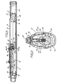
- the tubular body 2 designates the tubular body of the wrench, 3 the bending bar, 4 the drive head for removable clamping sleeves, 5 the slider for adjusting the value of the measured torque.
- the tubular body 2 has, in cross section, an ovoid shape. At its rear end, it has knock-outs 6 constituting notches for positioning the fingers of the hand. Finally, it has two windows 7 laterally, the usefulness of which will be specified below. Over a part of its length, this body is provided with a longitudinal slot 8 bordered by a machined bearing face 9 and in particular rectified to have good flatness.
- the connection of the end of the rod with the axis 12 is ensured by an oblong opening light 13 so as to allow the rod, a longitudinal displacement.
- the light 13 is replaced by a circular bore whose only manufacturing tolerances allow sufficient play with the axis 12.
- the slider 5 is composed of a plate 14 in frictional contact with the rectified face 9 of the body, of an inclined strip 15, arranged in the body, and of two studs 16 ensuring the connection of the plate 14 with the strip 15.
- the head of each of the studs 16 is made integral with the strip 15 by gluing or the like. Its threaded free end passes through the friction plate 14 to receive a nut 17.
- a spring 18, disposed around each stud 16 is interposed between the strip 15 and the body 2 to separate the strip of the body and thus ensure the automatic adjustment of the games.
- this spring bears on an intermediate piece 19 which, disposed inside the body, has a cross section similar to the upper half of this body and laterally includes graduations 20 formalizing the measurement scale and cooperating with a index finger 22 disposed in the lumen 7 of this body.
- the pre-alarm means indicating that the displayed torque is approaching, as well as the alarm means indicating that the displayed torque is reached, are constituted by electrical contacts associated with a dry battery 23 disposed in the posterior end of the tubular body 2.
- each contact is composed of an insulating well 29 with insulating bottom 30 in which is placed a contact ball 32 held in the extended position by a spring 33.
- the protrusion of the ball is limited by a projection provided at the upper end of the insulating well 29.
- the ball of each contact is electrically connected to the corresponding light-emitting diode 26 or 27 connected, moreover, by a common electrical connection 31, to the positive terminal of the battery 23.
- the other terminal of this battery is connected by an elastic tongue 11 to the body 2, and therefore by the cursor 5 to the strip 15.
- the value of the projection of the contacts 24 and 25 is identical since, by the inclination of the sloping contact face 15a of the strip 15, the space between each of the contacts and the face 15a is different, and the first contact that can be actuated is that 25 corresponding to the pre-alarm.
- the light emitting diodes 26a and 27a are carried by the wafer 15. These two diodes are connected directly by a circuit 36 to the positive terminal of the battery 23. In addition, each of 'they are electrically connected by a circuit respectively, 38 and 39 to two conductive tracks, respectively, 38a and 39a, formed on the bearing face 15a of an insulating plate 15b attached to the 15 opposite two contacts 24a- 25a.
- the alarm diode 27a is connected by a circuit 37 to the audible alarm 28.
- a circuit 42 connects the negative terminal of the battery and the axis 12, and, consequently, this terminal with the bending bar 3 and the contacts 24a and 25a embedded in this bar. As shown in more detail in FIG.
- each of the two contacts 24a and 25a, arranged side by side and transversely in conductive wells of the bending bar 3, is composed of a key 40 subjected to the action of a spring 41 tending to project it outwards.
- the key 40 of the contact 25a corresponding to the pre-alarm exceeds the flexion bar 3 more than the key 40 of the contact 24a corresponding to the alarm.
- the friction plate 14 with the nuts 17 is protected by a glued cover 44 also constituting the actuator of the cursor and the member preventing access to the nuts.
- this cover has openings for the passage of light emitting diodes 26a-27a.
- the two extreme values of its measurement scale are adjusted.
- This adjustment has two phases. A first phase consisting in adjusting the low point of the scale corresponding to a zero value and, more generally, in a value of a few meters-kilograms and a second phase consisting in adjusting the high point of the scale.
- This adjustment is made on a measuring bench allowing communicate to the drive head of the key and consequently to the whole of the key, a reaction torque of defined but adjustable value, corresponding to the value of the torque displayed on the key, by the cursor 5 and visible on the gradation 20 through one of the windows 7.
- the adjustment of the low point of the measurement scale is therefore carried out by exerting on the drive head 4 a reaction torque corresponding to the value of the low point of the scale and by bringing the cursor 5, including the cover 44 has been removed, in the position where the scale value of the gradation coincides with the index 22 of the body.
- the strip 15 is moved transversely in the direction of the bar 3 until it comes into contact first with the pre-contact. alarm, 25 or 25a, then with the alarm contact 24 or 24a, which causes the corresponding light-emitting diode to light up and the horn 28 to operate.
- the cursor 5 is moved to the other end of the measurement scale, i.e. until the mark 22 on the body 2 coincides with the maximum value of the graduation 20 carried by the part 19.
- the nut 17 of the stud 16 disposed at the front end of the plate 14 is actuated until the strip 15 meets the contact 24 or 24a alarm. This operation finished, the cover 44 is put in place and glued to oppose any misadjustments.
- At least one of the studs 16 is disposed on the strip 15 so as to come above the alarm contact 24 or 24a when the cursor 5 is in a position corresponding to the coincidence with the index 22 of one of the extreme values of the measurement scale. In the embodiments, this superposition takes place when the index coincides with the bottom of scale value. This particular arrangement avoids any deterioration of the adjustment made for this bottom of scale value, when the alarm and tilting of the strip 15 for the high value of the measurement scale are adjusted.
- the adjustment of the strip for the high value of the measurement scale, adjustment being effected by actuation of the nut 17 of the front screw 16, causes a modification of the inclination of this strip relative to the general longitudinal axis of the key and a pivoting of this strip around the other stud, without any modification of the length adjustment made on the first stud.
- Such an arrangement of at least one of the studs therefore facilitates adjustment.
- the adjustment operation on a measurement bench also makes it possible, after adjusting the two extreme values, to check the operation of the key for all or part of the intermediate values shown on the scale 20.
- the plate 15 carrying the contact surface 15a is inclined so as to approach the bending bar 3 going towards the rear end of this bar. If the same results can be obtained with a reverse inclination of the insert, the arrangement presented is more advantageous because, when using the key for tightening with high torques, the cursor is moved towards the rear end of the key, that is to say on the zone which is less sensitive to possible deformations of the tubular body 2. In other words and although the moment of inertia of the tubular body is much greater than the moment of inertia of the bending bar 3, the inclination of the plate, retained in the embodiments shown, eliminates any risk of alteration of the measurement by possible deformations of the tubular body.
- the body 2 comprises, at the rear end of the bar 3, a cradle 43 visible in FIGS. 2 and 4.
- the contacts 24-25 and 24a-25a can indifferently be constituted by a ball 32 or by a pusher 40 provided that their electrical connections with the diodes and the body remain the same.
Claims (7)
Applications Claiming Priority (2)
| Application Number | Priority Date | Filing Date | Title |
|---|---|---|---|
| FR8804638 | 1988-04-01 | ||
| FR8804638A FR2629383B1 (fr) | 1988-04-01 | 1988-04-01 | Cle dynamometrique electromecanique |
Publications (2)
| Publication Number | Publication Date |
|---|---|
| EP0335809A1 EP0335809A1 (de) | 1989-10-04 |
| EP0335809B1 true EP0335809B1 (de) | 1991-08-14 |
Family
ID=9365091
Family Applications (1)
| Application Number | Title | Priority Date | Filing Date |
|---|---|---|---|
| EP19890420110 Expired - Lifetime EP0335809B1 (de) | 1988-04-01 | 1989-03-29 | Elektromechanischer Drehmomentschlüssel |
Country Status (4)
| Country | Link |
|---|---|
| EP (1) | EP0335809B1 (de) |
| DE (1) | DE68900197D1 (de) |
| ES (1) | ES2025851T3 (de) |
| FR (1) | FR2629383B1 (de) |
Families Citing this family (1)
| Publication number | Priority date | Publication date | Assignee | Title |
|---|---|---|---|---|
| FR2736858B1 (fr) * | 1995-07-18 | 1997-10-10 | Sam Outillage | Tournevis dynamometrique electromecanique a alarme sonore et/ou visuelle |
Family Cites Families (8)
| Publication number | Priority date | Publication date | Assignee | Title |
|---|---|---|---|---|
| US2250941A (en) * | 1938-05-21 | 1941-07-29 | Automotive Maintenance Mach Co | Torque measuring wrench |
| US2474247A (en) * | 1944-07-08 | 1949-06-28 | Hattan Mark | Signal type torque indicating wrench |
| US2440683A (en) * | 1944-09-13 | 1948-05-04 | Hattan Mark | Signal type torque indicating wrench |
| US2663209A (en) * | 1949-04-12 | 1953-12-22 | Buckeye Tools Corp | Torque indicating power operated tool |
| FR2131018A5 (de) * | 1971-03-30 | 1972-11-10 | Snap On Tools Corp | |
| US3763724A (en) * | 1971-07-26 | 1973-10-09 | Snap On Tools Corp | Automatic torque release wrench of the preset type |
| DE3026134A1 (de) * | 1980-07-10 | 1982-02-04 | Bayerische Motoren Werke AG, 8000 München | Drehmomentschluessel |
| CA1220367A (en) * | 1983-01-27 | 1987-04-14 | Repco Limited | Torque wrench |
-
1988
- 1988-04-01 FR FR8804638A patent/FR2629383B1/fr not_active Expired - Lifetime
-
1989
- 1989-03-29 ES ES89420110T patent/ES2025851T3/es not_active Expired - Lifetime
- 1989-03-29 EP EP19890420110 patent/EP0335809B1/de not_active Expired - Lifetime
- 1989-03-29 DE DE8989420110T patent/DE68900197D1/de not_active Expired - Lifetime
Also Published As
| Publication number | Publication date |
|---|---|
| ES2025851T3 (es) | 1992-04-01 |
| FR2629383A1 (fr) | 1989-10-06 |
| DE68900197D1 (de) | 1991-09-19 |
| FR2629383B1 (fr) | 1991-03-15 |
| EP0335809A1 (de) | 1989-10-04 |
Similar Documents
| Publication | Publication Date | Title |
|---|---|---|
| WO1995020109A1 (fr) | Frein a disque a securite accrue | |
| FR2695616A1 (fr) | Frein de bicyclette à leviers articulés. | |
| WO2005077585A1 (fr) | Outil de serrage, en particulier pince a souder, avec un systeme de compensation | |
| CA2127912C (fr) | Outil pour mesurer une force de serrage exercee par une tige mobile d'appareil de mesure de longueur | |
| EP0074883A1 (de) | Vorrichtung zur Übertragung geradliniger Bewegungen mittels Riemenscheiben und Treibriemen | |
| EP0335809B1 (de) | Elektromechanischer Drehmomentschlüssel | |
| FR2491007A1 (fr) | Detecteur de niveau de vehicule avec mecanisme de securite | |
| EP0385945B1 (de) | Skibindung mit einer Sohlenplatte | |
| EP2214066A1 (de) | Korrekturvorrichtung für Uhrwerk, das mit zwei Zeitanzeigeorganen ausgestattet ist | |
| EP0260583A1 (de) | Taster zur Dimensionsmessung | |
| FR2746957A1 (fr) | Mecanisme de commande d'un disjoncteur a grand angle d'ouverture | |
| EP0192547B1 (de) | Betätigungseinrichtung für Doppelhauptbremszylinder | |
| EP0446770B1 (de) | Wecker | |
| WO2017149211A1 (fr) | Capteur de deformation permettant une discrimination de mesure en fonction de la direction de la deformation | |
| EP0760524A1 (de) | Vorrichtung zum einstellen eines thermischen auslösers einer schutzschalter | |
| FR2531895A1 (fr) | Cle de serrage | |
| FR2584494A1 (fr) | Dispositif polyvalent d'etalonnage et de controle du couple de serrage d'un organe de liaison du type vis-ecrou. | |
| FR2633544A1 (fr) | Cle dynamometrique a detection electrique | |
| EP1610026B1 (de) | Bremssattel für eine elektromechanische Scheibenbremse | |
| FR2780324A1 (fr) | Dispositif de positionnement, de maintien ou de serrage | |
| EP0483008B1 (de) | Linsenausrichtgerät mit Drehtisch | |
| FR2506938A1 (fr) | Dispositif pour mesurer la tension d'un cordage, notamment un cordage de raquette de tennis | |
| EP1069038B1 (de) | Automatisches Pedal für Mountainbike | |
| FR2574588A1 (fr) | " manche a balai " | |
| EP1926573B1 (de) | Drehmomentschlüssel |
Legal Events
| Date | Code | Title | Description |
|---|---|---|---|
| PUAI | Public reference made under article 153(3) epc to a published international application that has entered the european phase |
Free format text: ORIGINAL CODE: 0009012 |
|
| 17P | Request for examination filed |
Effective date: 19890403 |
|
| AK | Designated contracting states |
Kind code of ref document: A1 Designated state(s): BE DE ES GB LU NL |
|
| 17Q | First examination report despatched |
Effective date: 19901114 |
|
| GRAA | (expected) grant |
Free format text: ORIGINAL CODE: 0009210 |
|
| AK | Designated contracting states |
Kind code of ref document: B1 Designated state(s): BE DE ES GB LU NL |
|
| REF | Corresponds to: |
Ref document number: 68900197 Country of ref document: DE Date of ref document: 19910919 |
|
| GBT | Gb: translation of ep patent filed (gb section 77(6)(a)/1977) | ||
| REG | Reference to a national code |
Ref country code: ES Ref legal event code: FG2A Ref document number: 2025851 Country of ref document: ES Kind code of ref document: T3 |
|
| PLBE | No opposition filed within time limit |
Free format text: ORIGINAL CODE: 0009261 |
|
| STAA | Information on the status of an ep patent application or granted ep patent |
Free format text: STATUS: NO OPPOSITION FILED WITHIN TIME LIMIT |
|
| 26N | No opposition filed | ||
| EPTA | Lu: last paid annual fee | ||
| PGFP | Annual fee paid to national office [announced via postgrant information from national office to epo] |
Ref country code: NL Payment date: 20000331 Year of fee payment: 12 |
|
| PGFP | Annual fee paid to national office [announced via postgrant information from national office to epo] |
Ref country code: LU Payment date: 20000405 Year of fee payment: 12 |
|
| PGFP | Annual fee paid to national office [announced via postgrant information from national office to epo] |
Ref country code: DE Payment date: 20010315 Year of fee payment: 13 |
|
| PGFP | Annual fee paid to national office [announced via postgrant information from national office to epo] |
Ref country code: GB Payment date: 20010328 Year of fee payment: 13 |
|
| PG25 | Lapsed in a contracting state [announced via postgrant information from national office to epo] |
Ref country code: LU Free format text: LAPSE BECAUSE OF NON-PAYMENT OF DUE FEES Effective date: 20010329 |
|
| PG25 | Lapsed in a contracting state [announced via postgrant information from national office to epo] |
Ref country code: NL Free format text: LAPSE BECAUSE OF NON-PAYMENT OF DUE FEES Effective date: 20011001 |
|
| NLV4 | Nl: lapsed or anulled due to non-payment of the annual fee |
Effective date: 20011001 |
|
| REG | Reference to a national code |
Ref country code: GB Ref legal event code: IF02 |
|
| PG25 | Lapsed in a contracting state [announced via postgrant information from national office to epo] |
Ref country code: GB Free format text: LAPSE BECAUSE OF NON-PAYMENT OF DUE FEES Effective date: 20020329 |
|
| PG25 | Lapsed in a contracting state [announced via postgrant information from national office to epo] |
Ref country code: DE Free format text: LAPSE BECAUSE OF NON-PAYMENT OF DUE FEES Effective date: 20021001 |
|
| GBPC | Gb: european patent ceased through non-payment of renewal fee |
Effective date: 20020329 |
|
| PGFP | Annual fee paid to national office [announced via postgrant information from national office to epo] |
Ref country code: ES Payment date: 20050317 Year of fee payment: 17 |
|
| PGFP | Annual fee paid to national office [announced via postgrant information from national office to epo] |
Ref country code: BE Payment date: 20050418 Year of fee payment: 17 |
|
| PG25 | Lapsed in a contracting state [announced via postgrant information from national office to epo] |
Ref country code: ES Free format text: LAPSE BECAUSE OF NON-PAYMENT OF DUE FEES Effective date: 20060330 |
|
| PG25 | Lapsed in a contracting state [announced via postgrant information from national office to epo] |
Ref country code: BE Free format text: LAPSE BECAUSE OF NON-PAYMENT OF DUE FEES Effective date: 20060331 |
|
| REG | Reference to a national code |
Ref country code: ES Ref legal event code: FD2A Effective date: 20060330 |
|
| BERE | Be: lapsed |
Owner name: S.A. *SAM OUTILLAGE Effective date: 20060331 |