EP0335735B1 - A process for firing ceramic shaped bodies and a tunnel kiln used therefor - Google Patents
A process for firing ceramic shaped bodies and a tunnel kiln used therefor Download PDFInfo
- Publication number
- EP0335735B1 EP0335735B1 EP19890303202 EP89303202A EP0335735B1 EP 0335735 B1 EP0335735 B1 EP 0335735B1 EP 19890303202 EP19890303202 EP 19890303202 EP 89303202 A EP89303202 A EP 89303202A EP 0335735 B1 EP0335735 B1 EP 0335735B1
- Authority
- EP
- European Patent Office
- Prior art keywords
- temperature
- firing
- tunnel kiln
- preheating zone
- zone
- Prior art date
- Legal status (The legal status is an assumption and is not a legal conclusion. Google has not performed a legal analysis and makes no representation as to the accuracy of the status listed.)
- Expired - Lifetime
Links
Images

Classifications
-
- C—CHEMISTRY; METALLURGY
- C04—CEMENTS; CONCRETE; ARTIFICIAL STONE; CERAMICS; REFRACTORIES
- C04B—LIME, MAGNESIA; SLAG; CEMENTS; COMPOSITIONS THEREOF, e.g. MORTARS, CONCRETE OR LIKE BUILDING MATERIALS; ARTIFICIAL STONE; CERAMICS; REFRACTORIES; TREATMENT OF NATURAL STONE
- C04B38/00—Porous mortars, concrete, artificial stone or ceramic ware; Preparation thereof
- C04B38/0006—Honeycomb structures
-
- C—CHEMISTRY; METALLURGY
- C04—CEMENTS; CONCRETE; ARTIFICIAL STONE; CERAMICS; REFRACTORIES
- C04B—LIME, MAGNESIA; SLAG; CEMENTS; COMPOSITIONS THEREOF, e.g. MORTARS, CONCRETE OR LIKE BUILDING MATERIALS; ARTIFICIAL STONE; CERAMICS; REFRACTORIES; TREATMENT OF NATURAL STONE
- C04B33/00—Clay-wares
- C04B33/32—Burning methods
-
- C—CHEMISTRY; METALLURGY
- C04—CEMENTS; CONCRETE; ARTIFICIAL STONE; CERAMICS; REFRACTORIES
- C04B—LIME, MAGNESIA; SLAG; CEMENTS; COMPOSITIONS THEREOF, e.g. MORTARS, CONCRETE OR LIKE BUILDING MATERIALS; ARTIFICIAL STONE; CERAMICS; REFRACTORIES; TREATMENT OF NATURAL STONE
- C04B35/00—Shaped ceramic products characterised by their composition; Ceramics compositions; Processing powders of inorganic compounds preparatory to the manufacturing of ceramic products
- C04B35/622—Forming processes; Processing powders of inorganic compounds preparatory to the manufacturing of ceramic products
- C04B35/64—Burning or sintering processes
-
- F—MECHANICAL ENGINEERING; LIGHTING; HEATING; WEAPONS; BLASTING
- F27—FURNACES; KILNS; OVENS; RETORTS
- F27B—FURNACES, KILNS, OVENS, OR RETORTS IN GENERAL; OPEN SINTERING OR LIKE APPARATUS
- F27B9/00—Furnaces through which the charge is moved mechanically, e.g. of tunnel type; Similar furnaces in which the charge moves by gravity
- F27B9/30—Details, accessories, or equipment peculiar to furnaces of these types
- F27B9/3005—Details, accessories, or equipment peculiar to furnaces of these types arrangements for circulating gases
Definitions
- the present invention relates to a process for firing ceramic shaped bodies, particularly ceramic honeycomb structural bodies, and to a firing kiln adapted for effecting such a process.
- a tunnel kiln as shown in Fig. 4 has been used for firing ceramic honeycomb structural bodies with a view to mass production.
- the tunnel kiln is generally constituted by a preheating zone 11, a firing zone 12, and a waste heat zone 13.
- Combustion gases generated from combustion burners 14 provided at the firing zone 12 are evacuated outside the kiln through the preheating zone 11 by suction of an exhaust fan 15 provided at a low temperature section of the preheating zone 11 on the inlet side.
- the firing condition is constituted by a temperature-rising section, a sintering section in which a constant temperature is maintained, and a temperature-descending section.
- the firing kiln according to the present invention is set out in claim 2.
- the ceramic-firing conditions of this process can be attained merely by providing the exhaust means at the high temperature section of the preheating zone on the outlet side.
- the ceramic-firing process and apparatus according to the present invention are based on knowledge obtained by examining conventional firing kilns and their firing conditions.
- the temperature distribution in the outer surface and the inside of the ceramic shaped body under the conventional firing conditions is that a shaping aid contained in the shaped body is thermally decomposed at 150 to 300 ° C, and owing to this, heat is first generated at the outer periphery of the ceramic shaped body, and then generated inside. Although heat generated at the outer periphery is easily dissipated, heat generated inside is accumulated without being dissipated. Therefore, it is found out that as shown in Fig. 6, a temperature difference occurs between the outer surface and the inside of the ceramic shaped body so that firing cracks are likely to occur. In particular, since extrusion shaping is employed for the ceramic honeycomb shaped bodies from the structural standpoint, a considerable amount of a shaping aid is contained. It is also found out that because partition walls defining through holes of the honeycomb are thin, firing cracks or thermal deformation is likely to occur due to slight change in temperature distribution.
- Fig. 1 shows for the relationship between the firing temperature and the time
- the heating rate in a temperature range from a firing-starting point A to a point B at which a shaping aid contained in a ceramic shaped body is thermally decomposed is smaller than in a temperature range from the point B to a sintering temperature C.
- the shaping aid may involve binders such as methyl cellulose, carboxylmethyl cellulose, polyvinyl alcohol, starch paste, etc., a surface active agent, a lubricant such as wax, and the like. Therefore, the thermal decomposition temperature is specifically determined depending upon the kind of shaping aid, and therefore, the heating rate can be determined based on the dimension and shape of the shaped body and the content of the shaping aid.
- a cordierite ceramic honeycomb structural body can be obtained by heating the shaped body such that the heating rate is set at 80 to 90 ° C/h in a range up to the decomposition temperature, 200 °C, of methyl cellulose, and at 100 to 120 ° C/h in a range from 200 ° C to 1,400 ° C at which the shaped body is maintained during sintering.
- the heating rate in the temperature range from the thermal decomposition temperature B to the sintering temperature C is set such that delay in raising the temperature from A to B is complemented.
- Fig. 2 is a concept view illustrating the construction of an embodiment of the tunnel kiln for effecting the firing process according to the present invention.
- the tunnel kiln is constituted by a preheating zone 1, a firing zone 2 and a waste heat zone 3.
- An exhaust fan 4 is provided at an inlet side of a low temperature section of the preheating zone 1 for evacuating combustion waste gas.
- Another exhaust fan 5 is provided at an outlet side of a high temperature section of the preheating zone 1 for evacuating the high temperature gas.
- the preheating zone 1 When the preheating zone 1 is constituted as above, the combustion gases generated by burners 6 positioned in the firing zone 2 are sucked by the exhaust fan 4 at the inlet side of the preheating zone 1 to generate the combustion gas stream, while the high temperature gas is sucked midway of this stream by means of the exhaust fan 5. Thereby, the firing condition as shown in Fig. 1 is attained for the tunnel kiln.
- the heating rate can arbitrarily be varied.
- the heating rate of the shaping aid in the ceramic shaped body to be fired can be retarded near the decomposition temperature thereof so that temperature difference between the inside and the outer portion of the shaped body due to the decomposition of the shaping aid can be diminished.
- Fig. 3 is a concept view illustrating another tunnel kiln for effecting the firing process according to the present invention.
- the same reference numerals in Fig. 2 are given to the same or similar parts in Fig.3 as in the embodiment of Fig. 2, and explanation thereof is omitted.
- the embodiment in Fig. 3 differs from that of Fig. 1 in that a high temperature gas at a high temperature section of a preheating zone 1 is evacuated by an exhaust fan 5, and supplied to a low temperature section of the preheating zone 1 through a temperature adjusting means 7.
- the circulated gas tends to pass on the upper side of the kiln, that is, on a ceiling side of the kiln, because the temperature of the circulated gas is high.
- temperature difference occurs between the kiln bottom portion and the kiln upper portion, so that firing cracks or deformation occur in the fired shaped body due to such a temperature difference.
- the gas once discharged outside the kiln by the exhaust fan 5 is circulated to the low temperature section of the preheating zone, thereby removing the temperature difference between the upper portion and the bottom portion of the kiln.
- the temperature of the combustion gas is controlled by a temperature adjuster 7 such as a heat exchanger or by changing the amount of the gas to be circulated.
- a temperature adjuster 7 such as a heat exchanger or by changing the amount of the gas to be circulated.
- the temperature adjuster 7 is depicted to have a flow-controlling function, but a flow controller may be provided separately from the temperature adjuster.
- the temperature of the preheating zone can be uniformalized, and heat inputs and outgoings can be improved by recycling the exhaust gas.
- the exhaust fan is provided at the high temperature section of the preheating zone at the outlet side for evacuating a given amount of the high temperature gas through the exhaust fan.
Description
- The present invention relates to a process for firing ceramic shaped bodies, particularly ceramic honeycomb structural bodies, and to a firing kiln adapted for effecting such a process.
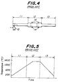
- Heretofore, a tunnel kiln as shown in Fig. 4 has been used for firing ceramic honeycomb structural bodies with a view to mass production. The tunnel kiln is generally constituted by a preheating zone 11, a
firing zone 12, and awaste heat zone 13. Combustion gases generated fromcombustion burners 14 provided at thefiring zone 12 are evacuated outside the kiln through the preheating zone 11 by suction of anexhaust fan 15 provided at a low temperature section of the preheating zone 11 on the inlet side. In the tunnel kiln of this structure, as shown in Fig. 5, the firing condition is constituted by a temperature-rising section, a sintering section in which a constant temperature is maintained, and a temperature-descending section. - However, if ceramic shaped bodies are fired under such firing conditions, firing cracks or deformation occur in some of the fired products. In particular, occurrence of such defects is more frequent in the case of ceramic honeycomb structural bodies having a number of through holes.
- It is an object of the present invention to solve the above-mentioned problems, and to provide a firing process which produces fired products free or more free from defects, as well as a tunnel kiln useful in the process.
- The process according to the present invention is set out in claim 1.
- The firing kiln according to the present invention is set out in claim 2.
- In the process, since the heating rate up to the decomposing temperature of the shaping aid is slow, thermal decomposition of the shaping aid is made uniform so that neither firing cracks nor firing deformation occur.
- Further, the ceramic-firing conditions of this process can be attained merely by providing the exhaust means at the high temperature section of the preheating zone on the outlet side.
- These and other optional features and advantages of the invention will be appreciated upon reading of the following description of the invention when taken in conjunction with the attached drawings, with the understanding that some modifications, variations, and changes of the same could be made by the skilled person in the art to which the invention pertains.
- For a better understanding of the invention, reference is made to the attached drawings, wherein:
- Fig. 1 is a diagram showing a firing condition of an example of the ceramic-firing process according to the present invention;
- Fig. 2 is a side view of a tunnel kiln as an embodiment of the present invention;
- Fig. 3 is a concept view illustrating the construction of another embodiment of the tunnel kiln for effecting the firing process according to the present invention;
- Fig. 4 is a concept view illustrating the construction of a tunnel kiln for effecting a conventional firing process;
- Fig. 5 is a diagram illustrating an example of a heat curve of the tunnel kiln shown in Fig. 4; and
- Fig. 6 is a diagram illustrating differences in temperature between an inner portion and an outer portion of a fired product obtained by the conventional process.
- The ceramic-firing process and apparatus according to the present invention are based on knowledge obtained by examining conventional firing kilns and their firing conditions.
- That is, the temperature distribution in the outer surface and the inside of the ceramic shaped body under the conventional firing conditions is that a shaping aid contained in the shaped body is thermally decomposed at 150 to 300 ° C, and owing to this, heat is first generated at the outer periphery of the ceramic shaped body, and then generated inside. Although heat generated at the outer periphery is easily dissipated, heat generated inside is accumulated without being dissipated. Therefore, it is found out that as shown in Fig. 6, a temperature difference occurs between the outer surface and the inside of the ceramic shaped body so that firing cracks are likely to occur. In particular, since extrusion shaping is employed for the ceramic honeycomb shaped bodies from the structural standpoint, a considerable amount of a shaping aid is contained. It is also found out that because partition walls defining through holes of the honeycomb are thin, firing cracks or thermal deformation is likely to occur due to slight change in temperature distribution.
- Therefore, as Fig. 1 shows for the relationship between the firing temperature and the time, according to the ceramic-firing process of the present invention, the heating rate in a temperature range from a firing-starting point A to a point B at which a shaping aid contained in a ceramic shaped body is thermally decomposed is smaller than in a temperature range from the point B to a sintering temperature C.
- The shaping aid may involve binders such as methyl cellulose, carboxylmethyl cellulose, polyvinyl alcohol, starch paste, etc., a surface active agent, a lubricant such as wax, and the like. Therefore, the thermal decomposition temperature is specifically determined depending upon the kind of shaping aid, and therefore, the heating rate can be determined based on the dimension and shape of the shaped body and the content of the shaping aid.
- For instance, when a body in which a shaping aid mainly composed of methyl cellulose is added to raw materials of talc, kaolin and alumina is extruded in the form of a honeycomb structure, a cordierite ceramic honeycomb structural body can be obtained by heating the shaped body such that the heating rate is set at 80 to 90 ° C/h in a range up to the decomposition temperature, 200 °C, of methyl cellulose, and at 100 to 120°C/h in a range from 200 ° C to 1,400 ° C at which the shaped body is maintained during sintering.
- The heating rate in the temperature range from the thermal decomposition temperature B to the sintering temperature C is set such that delay in raising the temperature from A to B is complemented.
- Next, the firing kiln according to the present invention will be explained in more detail below with reference to the attached drawings.
- Fig. 2 is a concept view illustrating the construction of an embodiment of the tunnel kiln for effecting the firing process according to the present invention. In this embodiment, the tunnel kiln is constituted by a preheating zone 1, a firing zone 2 and a waste heat zone 3. An exhaust fan 4 is provided at an inlet side of a low temperature section of the preheating zone 1 for evacuating combustion waste gas. Another exhaust fan 5 is provided at an outlet side of a high temperature section of the preheating zone 1 for evacuating the high temperature gas.
- When the preheating zone 1 is constituted as above, the combustion gases generated by burners 6 positioned in the firing zone 2 are sucked by the exhaust fan 4 at the inlet side of the preheating zone 1 to generate the combustion gas stream, while the high temperature gas is sucked midway of this stream by means of the exhaust fan 5. Thereby, the firing condition as shown in Fig. 1 is attained for the tunnel kiln. By varying the exhaust amount of the high temperature gas through the exhaust fan 5, the heating rate can arbitrarily be varied. As a result, the heating rate of the shaping aid in the ceramic shaped body to be fired can be retarded near the decomposition temperature thereof so that temperature difference between the inside and the outer portion of the shaped body due to the decomposition of the shaping aid can be diminished.
- Fig. 3 is a concept view illustrating another tunnel kiln for effecting the firing process according to the present invention. The same reference numerals in Fig. 2 are given to the same or similar parts in Fig.3 as in the embodiment of Fig. 2, and explanation thereof is omitted. The embodiment in Fig. 3 differs from that of Fig. 1 in that a high temperature gas at a high temperature section of a preheating zone 1 is evacuated by an exhaust fan 5, and supplied to a low temperature section of the preheating zone 1 through a temperature adjusting means 7.
- When a large amount of the combustion gas is evacuated outside the kiln by means of the exhaust fan 5 to decrease the temperature-rising rate in the preheating zone as a temperature zone in which the shaping aid is decomposed, an amount of the gas circulated to the side of the exhaust fan 4 on the inlet side of the tunnel kiln decreases.
- When the amount of the circulated gas decreases, the circulated gas tends to pass on the upper side of the kiln, that is, on a ceiling side of the kiln, because the temperature of the circulated gas is high. As a result, temperature difference occurs between the kiln bottom portion and the kiln upper portion, so that firing cracks or deformation occur in the fired shaped body due to such a temperature difference.
- In order to prevent this phenomenon, the gas once discharged outside the kiln by the exhaust fan 5 is circulated to the low temperature section of the preheating zone, thereby removing the temperature difference between the upper portion and the bottom portion of the kiln.
- The temperature of the combustion gas is controlled by a temperature adjuster 7 such as a heat exchanger or by changing the amount of the gas to be circulated. In Fig. 3, the temperature adjuster 7 is depicted to have a flow-controlling function, but a flow controller may be provided separately from the temperature adjuster.
- In the above construction, the temperature of the preheating zone can be uniformalized, and heat inputs and outgoings can be improved by recycling the exhaust gas.
- Although a single exhaust fan is provided in each of the low and high temperature sections of the preheating zone at the inlet side and the outlet side, respectively, in the above-mentioned embodiments, needless to say, the number of exhaust fans is not limited to one.
- As is clear from the foregoing explanation, according to the firing process of the present invention, since the thermal decomposition of the shaping aid gradually proceeds, neither firing cracks nor deformation occur. Furthermore, in the tunnel kiln according to the present invention, the exhaust fan is provided at the high temperature section of the preheating zone at the outlet side for evacuating a given amount of the high temperature gas through the exhaust fan. Thereby, desired firing conditions can be attained during the firing. Consequently, since the temperature difference between the inner portion and the outer portion of the shaped body during the firing is removed, fired products free from cracks can be obtained.
Claims (4)
Applications Claiming Priority (3)
| Application Number | Priority Date | Filing Date | Title |
|---|---|---|---|
| JP7644588 | 1988-03-31 | ||
| JP63076445A JP2543565B2 (en) | 1988-03-31 | 1988-03-31 | Tunnel furnace used for firing ceramics |
| JP76445/88 | 1988-03-31 |
Publications (4)
| Publication Number | Publication Date |
|---|---|
| EP0335735A2 EP0335735A2 (en) | 1989-10-04 |
| EP0335735A3 EP0335735A3 (en) | 1991-09-11 |
| EP0335735B1 true EP0335735B1 (en) | 1993-06-16 |
| EP0335735B2 EP0335735B2 (en) | 2000-11-08 |
Family
ID=13605352
Family Applications (1)
| Application Number | Title | Priority Date | Filing Date |
|---|---|---|---|
| EP19890303202 Expired - Lifetime EP0335735B2 (en) | 1988-03-31 | 1989-03-31 | A process for firing ceramic shaped bodies and a tunnel kiln used therefor |
Country Status (3)
| Country | Link |
|---|---|
| EP (1) | EP0335735B2 (en) |
| JP (1) | JP2543565B2 (en) |
| DE (1) | DE68907105T3 (en) |
Cited By (1)
| Publication number | Priority date | Publication date | Assignee | Title |
|---|---|---|---|---|
| CN108061463A (en) * | 2017-12-20 | 2018-05-22 | 长沙市西欧电子科技有限公司 | A kind of environmental protection de-waxing dumping kiln |
Families Citing this family (17)
| Publication number | Priority date | Publication date | Assignee | Title |
|---|---|---|---|---|
| DE4420295C1 (en) * | 1994-06-10 | 1995-10-26 | Riedhammer Gmbh Co Kg | Continuous furnace |
| JP3022195B2 (en) * | 1994-09-05 | 2000-03-15 | 日本碍子株式会社 | Method for firing ceramic compact and combustion apparatus used for firing method |
| JP3138656B2 (en) * | 1997-03-28 | 2001-02-26 | 日本碍子株式会社 | Method for firing ceramic molded body |
| JP3202945B2 (en) * | 1997-09-02 | 2001-08-27 | 日本碍子株式会社 | Method for firing ceramic honeycomb structure |
| KR20010033449A (en) * | 1997-12-22 | 2001-04-25 | 알프레드 엘. 미첼슨 | Method for firing ceramic honeycomb bodies and a tunnel kiln used therefor |
| AU2002255363A1 (en) | 2002-04-10 | 2003-10-20 | Lg Electronics Inc. | Method for controlling home automation system |
| JP4311609B2 (en) * | 2002-07-26 | 2009-08-12 | 日本碍子株式会社 | Method for producing porous ceramic body |
| JP4222600B2 (en) * | 2003-01-07 | 2009-02-12 | 日本碍子株式会社 | Method for firing ceramic honeycomb structure |
| JPWO2006006667A1 (en) | 2004-07-14 | 2008-05-01 | 日本碍子株式会社 | Method for manufacturing porous honeycomb structure |
| JP4899814B2 (en) * | 2006-11-15 | 2012-03-21 | 株式会社デンソー | Manufacturing method of exhaust gas purification filter |
| JP2008119664A (en) * | 2006-11-15 | 2008-05-29 | Denso Corp | Manufacturing method of exhaust gas purifying filter |
| JP2008119666A (en) * | 2006-11-15 | 2008-05-29 | Denso Corp | Manufacturing method of exhaust gas purifying filter |
| JP5603555B2 (en) * | 2009-02-06 | 2014-10-08 | 日本碍子株式会社 | Heat treatment method for the object to be heat treated |
| US8444737B2 (en) * | 2009-02-27 | 2013-05-21 | Corning Incorporated | Ceramic structures and methods of making ceramic structures |
| DE102009026251A1 (en) * | 2009-07-24 | 2011-02-03 | Thyssenkrupp Steel Europe Ag | Method and device for energy-efficient hot forming |
| CN110577407A (en) * | 2019-09-19 | 2019-12-17 | 孟津青城古建制品有限公司 | Method for controlling sintering curve of antique city wall brick |
| CN113620697B (en) * | 2021-08-12 | 2022-06-21 | 亚细亚建筑材料股份有限公司 | Low-temperature fast-fired ceramic and preparation method thereof |
Family Cites Families (7)
| Publication number | Priority date | Publication date | Assignee | Title |
|---|---|---|---|---|
| JPS5327726A (en) * | 1976-08-26 | 1978-03-15 | Yamaha Motor Co Ltd | Multicylinder internal combustion engine |
| JPS5610544A (en) * | 1979-07-07 | 1981-02-03 | Matsushita Electric Works Ltd | Phenol resin molding compound |
| JPS57119843A (en) * | 1981-01-20 | 1982-07-26 | Kobe Steel Ltd | Calcining method for catalyst carrier molding |
| JPS6025720A (en) * | 1983-07-22 | 1985-02-08 | Matsushita Electric Ind Co Ltd | Injection molder |
| FR2584805B1 (en) * | 1985-07-12 | 1989-07-13 | Elect Meca Et Const | IMPROVEMENT IN DRYING AND COOKING PLANTS FOR CERAMIC PRODUCTS |
| EP0232342A1 (en) * | 1985-07-19 | 1987-08-19 | Andreas Hässler | Process for operating a tunnel oven |
| DE3632918A1 (en) * | 1986-09-27 | 1988-06-09 | Haessler Andreas | Tunnel kiln with bypass afterburning |
-
1988
- 1988-03-31 JP JP63076445A patent/JP2543565B2/en not_active Expired - Lifetime
-
1989
- 1989-03-31 DE DE1989607105 patent/DE68907105T3/en not_active Expired - Lifetime
- 1989-03-31 EP EP19890303202 patent/EP0335735B2/en not_active Expired - Lifetime
Cited By (1)
| Publication number | Priority date | Publication date | Assignee | Title |
|---|---|---|---|---|
| CN108061463A (en) * | 2017-12-20 | 2018-05-22 | 长沙市西欧电子科技有限公司 | A kind of environmental protection de-waxing dumping kiln |
Also Published As
| Publication number | Publication date |
|---|---|
| EP0335735A3 (en) | 1991-09-11 |
| JPH01249665A (en) | 1989-10-04 |
| DE68907105D1 (en) | 1993-07-22 |
| JP2543565B2 (en) | 1996-10-16 |
| DE68907105T2 (en) | 1993-12-02 |
| EP0335735B2 (en) | 2000-11-08 |
| EP0335735A2 (en) | 1989-10-04 |
| DE68907105T3 (en) | 2001-05-10 |
Similar Documents
| Publication | Publication Date | Title |
|---|---|---|
| EP0335735B1 (en) | A process for firing ceramic shaped bodies and a tunnel kiln used therefor | |
| JP4869295B2 (en) | Method for firing ceramic honeycomb body | |
| US7017278B2 (en) | Microwave drying method | |
| US5046946A (en) | Process for firing ceramic shaped bodies and a tunnel kiln used therefor | |
| EP2366970B1 (en) | Method of drying a honeycomb formed body | |
| EP1264971B1 (en) | Method for manufacturing an exhaust gas purifying filter | |
| US4927577A (en) | Process for firing ceramic honeycomb structural bodies | |
| JP2981034B2 (en) | Method for firing ceramic honeycomb structure | |
| US5183609A (en) | Method of manufacturing ceramic honeycomb-structural body | |
| KR101419291B1 (en) | Process for producing cordierite ceramic honeycomb filter | |
| JPH03275309A (en) | Manufacture of ceramic honeycomb structure | |
| JP4311609B2 (en) | Method for producing porous ceramic body | |
| EP2681174B1 (en) | Method for manufacturing porous ceramic articles with reduced shrinkage | |
| JP2553192B2 (en) | Firing method of ceramic honeycomb structure | |
| US20070264376A1 (en) | Jig for baking ceramic honeycomb moldings | |
| CN111718190A (en) | Method for manufacturing ceramic honeycomb structure | |
| JP4453117B2 (en) | Method for manufacturing hexagonal honeycomb structure | |
| JP2002160976A (en) | Method for manufacturing ceramic honeycomb structure | |
| JP5362550B2 (en) | Method for drying honeycomb formed body | |
| JP2008110537A (en) | Manufacturing method of honeycomb structure and drying device used therein | |
| BE1014088A3 (en) | PROCESS FOR COOKING CERAMIC ALVEOLAR STRUCTURAL BODIES. | |
| US20220203575A1 (en) | Methods and apparatus for microwave drying of green ceramic honeycomb bodies using adjustable air flow | |
| EP2233871B1 (en) | Method for firing Si-bonded SiC ceramics | |
| JP2004292292A (en) | Method for firing ceramic honeycomb structure | |
| JPH07241476A (en) | Production of honeycomb catalyst |
Legal Events
| Date | Code | Title | Description |
|---|---|---|---|
| PUAI | Public reference made under article 153(3) epc to a published international application that has entered the european phase |
Free format text: ORIGINAL CODE: 0009012 |
|
| AK | Designated contracting states |
Kind code of ref document: A2 Designated state(s): BE DE FR GB |
|
| PUAL | Search report despatched |
Free format text: ORIGINAL CODE: 0009013 |
|
| AK | Designated contracting states |
Kind code of ref document: A3 Designated state(s): BE DE FR GB |
|
| 17P | Request for examination filed |
Effective date: 19910829 |
|
| 17Q | First examination report despatched |
Effective date: 19920327 |
|
| GRAA | (expected) grant |
Free format text: ORIGINAL CODE: 0009210 |
|
| AK | Designated contracting states |
Kind code of ref document: B1 Designated state(s): BE DE FR GB |
|
| REF | Corresponds to: |
Ref document number: 68907105 Country of ref document: DE Date of ref document: 19930722 |
|
| ET | Fr: translation filed | ||
| PLBI | Opposition filed |
Free format text: ORIGINAL CODE: 0009260 |
|
| PGFP | Annual fee paid to national office [announced via postgrant information from national office to epo] |
Ref country code: FR Payment date: 19940316 Year of fee payment: 6 |
|
| PGFP | Annual fee paid to national office [announced via postgrant information from national office to epo] |
Ref country code: GB Payment date: 19940321 Year of fee payment: 6 |
|
| PLBI | Opposition filed |
Free format text: ORIGINAL CODE: 0009260 |
|
| PLAB | Opposition data, opponent's data or that of the opponent's representative modified |
Free format text: ORIGINAL CODE: 0009299OPPO |
|
| 26 | Opposition filed |
Opponent name: RIEDHAMMER GMBH & CO.KG Effective date: 19940302 |
|
| 26 | Opposition filed |
Opponent name: RIEDHAMMER GMBH & CO.KG Effective date: 19940302 Opponent name: HANS LINGL ANLAGENBAU UND VERFAHRENSTECHNIK GMBH & Effective date: 19940316 |
|
| R26 | Opposition filed (corrected) |
Opponent name: RIEDHAMMER GMBH & CO.KG * 940316 HANS LINGL ANLAG Effective date: 19940302 |
|
| PG25 | Lapsed in a contracting state [announced via postgrant information from national office to epo] |
Ref country code: GB Effective date: 19950331 |
|
| GBPC | Gb: european patent ceased through non-payment of renewal fee |
Effective date: 19950331 |
|
| PG25 | Lapsed in a contracting state [announced via postgrant information from national office to epo] |
Ref country code: FR Free format text: LAPSE BECAUSE OF NON-PAYMENT OF DUE FEES Effective date: 19951130 |
|
| PLAW | Interlocutory decision in opposition |
Free format text: ORIGINAL CODE: EPIDOS IDOP |
|
| APAA | Appeal reference recorded |
Free format text: ORIGINAL CODE: EPIDOS REFN |
|
| REG | Reference to a national code |
Ref country code: FR Ref legal event code: ST |
|
| APAC | Appeal dossier modified |
Free format text: ORIGINAL CODE: EPIDOS NOAPO |
|
| APAC | Appeal dossier modified |
Free format text: ORIGINAL CODE: EPIDOS NOAPO |
|
| APAE | Appeal reference modified |
Free format text: ORIGINAL CODE: EPIDOS REFNO |
|
| APAC | Appeal dossier modified |
Free format text: ORIGINAL CODE: EPIDOS NOAPO |
|
| PLAW | Interlocutory decision in opposition |
Free format text: ORIGINAL CODE: EPIDOS IDOP |
|
| PUAH | Patent maintained in amended form |
Free format text: ORIGINAL CODE: 0009272 |
|
| STAA | Information on the status of an ep patent application or granted ep patent |
Free format text: STATUS: PATENT MAINTAINED AS AMENDED |
|
| 27A | Patent maintained in amended form |
Effective date: 20001108 |
|
| AK | Designated contracting states |
Kind code of ref document: B2 Designated state(s): BE DE FR GB |
|
| APAH | Appeal reference modified |
Free format text: ORIGINAL CODE: EPIDOSCREFNO |
|
| PGFP | Annual fee paid to national office [announced via postgrant information from national office to epo] |
Ref country code: BE Payment date: 20060126 Year of fee payment: 18 |
|
| BERE | Be: lapsed |
Owner name: *NGK INSULATORS LTD Effective date: 20070331 |
|
| PG25 | Lapsed in a contracting state [announced via postgrant information from national office to epo] |
Ref country code: BE Free format text: LAPSE BECAUSE OF NON-PAYMENT OF DUE FEES Effective date: 20070331 |
|
| PGFP | Annual fee paid to national office [announced via postgrant information from national office to epo] |
Ref country code: DE Payment date: 20080331 Year of fee payment: 20 |