EP0335504B1 - Cylindre de levage activé par un fluide sous pression, particuliairement pour clapets de ventilation. - Google Patents
Cylindre de levage activé par un fluide sous pression, particuliairement pour clapets de ventilation. Download PDFInfo
- Publication number
- EP0335504B1 EP0335504B1 EP89301992A EP89301992A EP0335504B1 EP 0335504 B1 EP0335504 B1 EP 0335504B1 EP 89301992 A EP89301992 A EP 89301992A EP 89301992 A EP89301992 A EP 89301992A EP 0335504 B1 EP0335504 B1 EP 0335504B1
- Authority
- EP
- European Patent Office
- Prior art keywords
- pressure
- actuated
- lifting cylinder
- pressure fluid
- lifting rod
- Prior art date
- Legal status (The legal status is an assumption and is not a legal conclusion. Google has not performed a legal analysis and makes no representation as to the accuracy of the status listed.)
- Expired - Lifetime
Links
- 239000012530 fluid Substances 0.000 title claims description 46
- 238000009877 rendering Methods 0.000 claims description 2
- 238000009423 ventilation Methods 0.000 description 5
- 230000006835 compression Effects 0.000 description 4
- 238000007906 compression Methods 0.000 description 4
- 239000000779 smoke Substances 0.000 description 4
- 238000010276 construction Methods 0.000 description 2
- 238000011161 development Methods 0.000 description 2
- 230000018109 developmental process Effects 0.000 description 2
- 239000011521 glass Substances 0.000 description 2
- 230000009172 bursting Effects 0.000 description 1
- 230000006378 damage Effects 0.000 description 1
Images

Classifications
-
- F—MECHANICAL ENGINEERING; LIGHTING; HEATING; WEAPONS; BLASTING
- F15—FLUID-PRESSURE ACTUATORS; HYDRAULICS OR PNEUMATICS IN GENERAL
- F15B—SYSTEMS ACTING BY MEANS OF FLUIDS IN GENERAL; FLUID-PRESSURE ACTUATORS, e.g. SERVOMOTORS; DETAILS OF FLUID-PRESSURE SYSTEMS, NOT OTHERWISE PROVIDED FOR
- F15B15/00—Fluid-actuated devices for displacing a member from one position to another; Gearing associated therewith
- F15B15/20—Other details, e.g. assembly with regulating devices
- F15B15/26—Locking mechanisms
- F15B15/261—Locking mechanisms using positive interengagement, e.g. balls and grooves, for locking in the end positions
-
- A—HUMAN NECESSITIES
- A62—LIFE-SAVING; FIRE-FIGHTING
- A62C—FIRE-FIGHTING
- A62C2/00—Fire prevention or containment
- A62C2/06—Physical fire-barriers
- A62C2/24—Operating or controlling mechanisms
- A62C2/246—Operating or controlling mechanisms having non-mechanical actuators
- A62C2/248—Operating or controlling mechanisms having non-mechanical actuators pneumatic
Definitions
- the invention relates to a lifting cylinder which can be actuated by pressure fluid, preferably for opening and closing ventilating devices such as ventilating flaps for example, in a construction according to the preamble to claim 1.
- Lifting cylinders of the above-mentioned kind which can be actuated by pressure fluid are used, for example, for closing and opening ventilating devices, ventilating flaps, natural-lighting elements and the like in the roof and wall region of halls and the like.
- a lifting cylinder as known from EP-A-0 246 736, which can be actuated by pressure fluid, the lifting rod is adapted to be locked in each of two stroke end positions by means of a detent member which can be actuated by pressure fluid.
- the building and construction expense necessary for this is considerable and involves a large number of individual components.
- the locking in the respective end positions is effected even during normal operation for interior ventilation although here locking is generally not necessary, for example for safety reasons.
- Ventilating devices additionally also serve as fire-protection elements so that lifting cylinders of the kind mentioned at the beginning, which can be actuated by pressure fluid, are often also coupled to a device for automatic pressure actuation in case of fire, which device comprises a small glass flask which bursts for example when a critical operating temperature is exceeded, and a dischargeable compressed-air cartridge, so that in case of fire, the ventilating flaps can be forcibly transferred into the open position by means of the lifting cylinder after the compressed-air cartridge has been discharged. In this case, it is necessary to lock the lifting cylinder in its end position in order to maintain the automatic ventilation in the event of any destruction of the supply of pressure fluid.
- fire alarms generally also have to perform an important and decisive safety task in case of fire.
- fire-protection ventilation devices which can be actuated by lifting cylinders of conventional type, however, it may happen, as a result of the immediate automatic ventilation in case of fire, that fire alarms responding to smoke do not give any alarm signal.
- the lifting cylinder according to the invention which can be actuated by pressure fluid, is an inexpensive device which is simple to handle and which, with only a small number of components which are not susceptible to wear, is in a position to bring the ventilating flaps for example reliably into their open and closed positions, while the intermediate stroke position can be used as the lifting-rod end stroke position during normal operation for the daily supply of air to and removal of air from interior spaces.
- This intermediate stroke position can likewise be used, for example on an outbreak of fire, at first only to open the flaps, for example up to one or two thirds for a certain period of time or, by appropriate connection with regard to control, up to a moment when fire alarms have given an alarm signal, and only after that to bring the lifting rod, for example by discharge of a further pressure-fluid cartridge with a higher operating pressure, into the end position and to lock it there.
- Expensive, separate compressed-air connections which are extremely susceptible particularly in case of a disaster, are advantageously unnecesary to unlock the detent member, for which purpose an entrainment means may appropriately be provided on the lifting rod, by which means, as a result of the end stroke movement of the lifting rod, a retaining element locking the detent member in its detent position can be transferred into an operating position releasing the detent member or the detent member can be transferred into an actuating position rendering possible the locking of the lifting rod.
- the lifting cylinder according to the invention may have housing members which together define one or preferably two working pressure chambers of working pistons as well as internal guiding spaces.
- the lifting rod is guided for longitudinal movement inside the housing and its front end is adapted to be connected to a linkage or the like of ventilating flaps to be opened or closed.
- At least one working piston may appropriately be secured to the rear end of the lifting rod, which end has a surface for the action of pressure which can be acted upon, via the pressure-fluid connection preferably constructed in the rear housing portion, preferably with compressed air as pressure fluid so that the lifting rod can be moved pneumatically.
- the working piston provided at the rear end of the lifting rod is preferably the one which is responsible for unlocking the detent member and also for locking the detent rod whereas the further working piston disposed in front of this working piston, bears against the stop in the intermediate stroke position.
- a compression spring may be supported on the face of a working piston situated opposite to the surface for the action of pressure so that, after pressure relief, the working piston or the lifting rod can be transferred by means of spring force into the end stroke position in which the ventilating flaps should be closed.
- a detent member may be provided which is aligned for longitudinal movement perpendicular to the longitudinal axis of the lifting rod and can only be moved manually, by means of a ring for example, into an unlocking position, against the force of a spring.
- a preferably disc-shaped retaining member which surrounds the lifting rod and has a collar-shaped marginal extension may be provided which engages with its front ends in a marginal recess formed in the detent member, to retain the detent member in its detent position.
- the lifting rod may appropriately be made movable relative to the retaining element which is formed at the rear by a spring with a spring tension adapted to the operating pressure in case of disaster so that when the discharge pressure of a compressed-air cartridge is present for example, the retaining element is moved, by means of the entrainment means, against the force of the spring while as a result of this movement of the lifting rod, it is transferred into a position in which the front ends no longer engage in the marginal recess in the detent member so that the detent member is unlocked and can engage behind the entrainment means.
- the retaining element is provided with an internal receiving space which is adapted substantially to the dimensions of the entrainment means so that the latter are disposed in the receiving space.
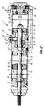
- the lifting cylinder numbered generally by 1 in the drawing shown in Figure 1 has housing portions 2, 3, 4 which, as a whole, define a working pressure chamber 5 and an internal guiding space 7.
- a lifting rod 8 with longitudinal central axis 9 is guided for longitudinal movement inside the housing and its front end is adapted to be connected to a linkage or the like of ventilating flaps to be opened or closed.
- the working piston 6 Secured to the rear end of the lifting rod 8 is the working piston 6 which is to be acted upon, at its surface 10 for the action of pressure, preferably by compressed air as a pressure fluid via a pressure-fluid connection formed in the rear housing portion 4 and not visible in detail in the drawing, so that the lifting rod 8 is adapted to be transferred pneumatically into a stroke position in which the ventilating flaps are opened.
- a compression spring not illustrated in detail, should be supported on the surface 11 situated opposite to the surface 10 for the action of pressure so that after the working pressure chamber has been relieved of pressure, the working piston 6 or the lifting rod 8 can be transferred, by means of spring force, into the stroke position illustrated in which the ventilating flaps are closed.
- a detent member numbered in general by 13 which is aligned for longitudinal movement perpendicular to the longitudinal axis 9 of the lifting rod and, after the lifting rod 8 has been locked, can only be unlocked manually by means of the ring 14.
- the detent member comprises a rod portion 15 which is supported via a spring 16.
- a contact member 17 and an entrainment means 19 which in turn comprises a locking marginal extension 18 which extends obliquely outwards.
- the contact member 17 is supported on the entrainment means 19 via a spring 22.
- the lifting rod can bear or be supported, via the front end of the contact member 17, against the contact surface 21, forming the stop, of the housing portion 2, in an intermediate stroke position, without the lifting rod being locked.
- This intermediate stroke position can be varied - in relation to the end travel - by the appropriate geometrical dimensions of the distance between contact surface 21 on the one hand and detent member on the other hand in the example of embodiment shown in Figure 1, or of the distance of the contact member 17 from the front end of the entrainment means 19.
- the end travel is only a few millimetres but may equally well be formed in such a manner that the ventilating flaps are only one or two thirds opened for example, for the more reliable response of a fire alarm in case of fire.
- the detent pin 15 of the detent member is moved slightly downwards against the force of the spring by means of the locking marginal extension, in the intermediate stroke position.
- the spring 22 is designed in such a manner that, at this operating pressure, the lifting rod still cannot undergo any further movement relative to the contact member 17.
- the housing portions 2, 3.1, 3.2, 3.3 and 4 together define two working pressure chambers 5.1 and 5.2 and guiding spaces 7.1, 7.2 respectively, in each of which a front working piston 6.1 or a rear working piston 6.2 is guided for longitudinal movement being able to be acted upon by pressure fluid.
- the working pressure chambers 5.1 and 5.2 are connected to a common pressure-fluid supply numbered in general by 23. From the pressure-fluid supply 23, the working pressure chamber 5.2 is adapted to be acted upon with pressure fluid via its pressure-fluid connection 24 and the working pressure chamber 5.1 is adapted to be supplied with pressure fluid through the connecting conduits 25, 26, 27.
- the pressure-fluid connection 24 of the working pressure chamber 5.2 is provided with a non-return valve 28. Furthermore, this working pressure chamber 5.2 also has a connecting conduit 30 controlled likewise by a non-return valve 29 so that when the pressure-fluid connection 24 is released, the working pressure chamber 5.1 can be connected to the working pressure chamber 5.2 through the connecting conduit 30 and the connecting conduits 26 and 27.
- the pressure-fluid inlet 23 can be connected to a pressure-fluid supply and to, for example, two pressure-fluid cartridges in each of which a pressure fluid is stored with a different pressure level.
- the control is then effected solely via the working pressure chamber 5.1 and the working piston 6.1 since the non-return valves are designed in such a manner that they only respond to a higher operating pressure of 10 bar for example.
- the stroke end position is formed by the intermediate stroke position in which - as illustrated in the drawing - the working piston 6.1 rests against the stop element 21 designed resiliently for example or in the form of a telescopic member with a response behaviour adapted to the operating pressures.
- a first pressure-fluid cartridge for example, is adapted to be discharged via actuating elements, for example via bursting glass bulbs and the like piercing units which can be released.
- the discharge pressure of this first cartridge is selected so that the working piston 6.1 is transferred into the position illustrated and hence the lifting rod is transferred into the intermediate stroke position in which the flaps are only partially opened, for example in a defined one-third position, in order to ensure that smoke detectors can give a signal.
- a pressure medium at 10 bar for example is then released so that the pressure medium can then pass through the non-return valve 28 into the working pressure chamber 5.2 and also, through the connecting conduits 30, 26, 27 into the working pressure chamber 5.1 so that, with compression of the stop element 21 and possibly of the spring 22, the lifting rod 8 can be transferred into its end stroke position while the lifting rod is automatically locked by means of the detent member 13 in a similar manner to that in the example of embodiment shown in Figure 1.
Landscapes
- Engineering & Computer Science (AREA)
- Health & Medical Sciences (AREA)
- Public Health (AREA)
- Business, Economics & Management (AREA)
- Emergency Management (AREA)
- Physics & Mathematics (AREA)
- Fluid Mechanics (AREA)
- Mechanical Engineering (AREA)
- General Engineering & Computer Science (AREA)
- Actuator (AREA)
Claims (13)
- Vérin de levage (1) qui peut être actionné par un fluide sous pression, destiné en particulier à ouvrir et à fermer des dispositifs de ventilation, tels que, par exemple, des volets de ventilation, comportant un piston de travail (6,6.1,6.2) qui est disposé sur une tige de levage (8) mobile longitudinalement et qui est guidée de manière à pouvoir se déplacer dans une chambre à pression de travail (5,5.1,5.2) comprenant un conduit de liaison (24,27) pour le fluide sous pression et ayant un loquet (13) sollicité par un ressort, lequel est de préférence aligné perpendiculairement à axe longitudinal (9) de la tige de levage, afin de verrouiller cette tige de levage dans sa position de fin de course, caractérisé en ce que la tige de levage (8) peut être appliquée contre une butée (21), dans une position intermédiaire de sa course, et, si une pression de fonctionnement qui peut être prédéterminée, est dépassée, elle peut être alors transférée dans sa position de fin de course.
- Vérin de levage pouvant être actionné par un fluide sous pression suivant la revendication 1 caractérisé en ce qu'à la tige de levage (8) est associé un moyen d'entraînement (19) si bien que, comme conséquence du mouvement final de la course de la tige de levage (8), un élément de retenue, bloquant le loquet (13) dans sa position de verrouillage, peut être transféré dans une position de fonctionnement libérant le loquet (13) ou bien le loquet peut être transféré dans une position active rendant possible le verrouillage de la tige de levage.
- Vérin de levage pouvant être actionné par un fluide sous pression suivant l'une quelconque des revendications 1 ou 2 caractérisé en ce que la tige de levage (8) comporte deux pistons de travail (6.1,6.2) espacés l'un de l'autre et à l'un au moins de ces pistons de travail (6.1) est associée une butée (17,21) pour supporter la tige de levage dans la position intermédiaire de sa course et ce qu'à l'un des pistons de travail (6.2) est associé le moyen d'entraînement (19) pour libérer ou débloquer le loquet.
- Vérin de levage pouvant être actionné par un fluide sous pression suivant la revendication 3 caractérisé en ce que les deux chambres à pression de travail (5.1,5.2) peuvent être reliées à une source commune de fluide sous pression (23) et la chambre à pression de travail (5.2) du piston de travail (6.2) comprenant le moyen d'entraînement (19) comporte un conduit de fluide sous pression (24) qui peut être ouvert uniquement lorsque la pression de fonctionnement prédéterminée est dépassée.
- Vérin de levage pouvant être actionné par un fluide sous pression suivant la revendication 4 caractérisé en ce que le conduit de fluide sous pression (24) peut être ouvert et fermé au moyen d'un clapet antiretour (28) sollicité par un ressort.
- Vérin de levage pouvant être actionné par un fluide sous pression suivant l'une quelconque des revendications 1 à 5 caractérisé en ce que la butée (17,21) est réalisée sous la forme d'un ressort ou d'un élément télescopique ayant un comportement en réponse sélectionnable à volonté.
- Vérin de levage pouvant être actionné par un fluide sous pression suivant l'une quelconque des revendications 2 à 6 caractérisé en ce que l'élément de retenue est supporté, sur le vérin de levage (1), par l'intermédiaire d'un ressort et ce ressort est conçu de telle façon que l'élément de retenue peut être déplacé à l'écart de la position de blocage, par l'intermédiaire du moyen d'entraînement (19), uniquement lorsque la pression de fonctionnement prédéterminée est dépassée.
- Vérin de levage pouvant être actionné par un fluide sous pression suivant l'une quelconque des revendications 2 à 7 caractérisé en ce que l'élément de retenue est réalisé sous la forme d'un disque entourant la tige de levage (8) et le loquet (13) comprend un creux marginal à son extrémité supérieure, creux dans lequel une région extrême avant de l'élément de retenue peut être introduite pour verrouiller le loquet.
- Vérin de levage pouvant être actionné par un fluide sous pression suivant l'une quelconque des revendications 2 à 8 caractérisé en ce que la tige de levage (8) peut être verrouillée par l'intermédiaire du moyen d'entraînement (19).
- Vérin de levage pouvant être actionné par un fluide sous pression suivant la revendication 9 caractérisé en ce que l'élément de retenue présente un espace de réception adapté sensiblement aux dimensions du moyen d'entraînement (19).
- Vérin de levage pouvant être actionné par un fluide sous pression suivant l'une quelconque des revendications 2 à 11 caractérisé en ce que le moyen d'entraînement (19) est précédé par un organe de contact (17) qui est supporté sur le moyen d'entraînement (19) par l'intermédiaire d'un ressort.
- Vérin de levage pouvant être actionné par un fluide sous pression suivant la revendication 9 caractérisé en ce que le moyen d'entraînement (19) comporte une saillie marginale de verrouillage (18), en forme de collerette, qui s'étend obliquement vers l'extérieur et en arrière de laquelle peut être verrouillé le loquet (13) qui peut être déverrouillé uniquement manuellement.
- Vérin de levage pouvant être actionné par un fluide sous pression suivant l'une quelconque des revendications 1 à 12 caractérisé en ce qu'au moins un piston de travail (6,6.1,6.2) peut être soumis à l'action d'un ressort de rappel.
Priority Applications (1)
| Application Number | Priority Date | Filing Date | Title |
|---|---|---|---|
| AT89301992T ATE82521T1 (de) | 1988-03-26 | 1989-02-28 | Mittels druckfluid aktivierbarer hubzylinder, insbesondere fuer lueftungsklappen. |
Applications Claiming Priority (4)
| Application Number | Priority Date | Filing Date | Title |
|---|---|---|---|
| DE8804119U DE8804119U1 (de) | 1988-03-26 | 1988-03-26 | Druckmittelbetätigbarer Hubzylinder für vorzugsweise Entlüftungseinrichtungen |
| DE8804119U | 1988-03-26 | ||
| DE3814003A DE3814003A1 (de) | 1988-03-26 | 1988-04-26 | Druckmittelbetaetigbarer hubzylinder fuer vorzugsweise entlueftungseinrichtungen |
| DE3814003 | 1988-04-26 |
Publications (2)
| Publication Number | Publication Date |
|---|---|
| EP0335504A1 EP0335504A1 (fr) | 1989-10-04 |
| EP0335504B1 true EP0335504B1 (fr) | 1992-11-19 |
Family
ID=25867395
Family Applications (1)
| Application Number | Title | Priority Date | Filing Date |
|---|---|---|---|
| EP89301992A Expired - Lifetime EP0335504B1 (fr) | 1988-03-26 | 1989-02-28 | Cylindre de levage activé par un fluide sous pression, particuliairement pour clapets de ventilation. |
Country Status (2)
| Country | Link |
|---|---|
| EP (1) | EP0335504B1 (fr) |
| DE (2) | DE3814003A1 (fr) |
Cited By (1)
| Publication number | Priority date | Publication date | Assignee | Title |
|---|---|---|---|---|
| CN104454779A (zh) * | 2014-10-13 | 2015-03-25 | 长沙迪普机械科技有限公司 | 一种带止动机构的线性致动器 |
Families Citing this family (1)
| Publication number | Priority date | Publication date | Assignee | Title |
|---|---|---|---|---|
| CN105257619B (zh) * | 2015-11-13 | 2017-12-05 | 湖南特力液压有限公司 | 液压缸 |
Citations (2)
| Publication number | Priority date | Publication date | Assignee | Title |
|---|---|---|---|---|
| DE3109684A1 (de) * | 1981-03-13 | 1982-09-23 | Zahnräderfabrik Renk AG, 8900 Augsburg | Stellvorrichtung zur erzeugung verschieden grosser linearbewegungen |
| EP0246736A1 (fr) * | 1986-03-22 | 1987-11-25 | Colt International Holdings A.G. | Dispositif pneumatique comportant piston et cylindre à double effet |
Family Cites Families (6)
| Publication number | Priority date | Publication date | Assignee | Title |
|---|---|---|---|---|
| DE109684C (fr) * | ||||
| FR994333A (fr) * | 1945-01-16 | 1951-11-15 | F Brasseur Sa Des Atel | Moteur pour couloir oscillant |
| US2582512A (en) * | 1948-06-07 | 1952-01-15 | Deere & Co | Multispeed and multistroke fluidpressure apparatus |
| DE2408200A1 (de) * | 1974-02-20 | 1975-08-28 | Grescha Ges Grefe & Scharf | Vorrichtung zur fernbetaetigung von fluegeln von rauch- und waermeabzugsanlagen |
| DE2634565A1 (de) * | 1976-07-31 | 1978-02-02 | Iva Ingenieurgesellschaft Mbh | Einrichtung zum oeffnen einer kombinierten lueftungs-rauch- und waermeabzugsklappe |
| DE3008995C2 (de) * | 1980-03-08 | 1982-07-15 | Heinz Essmann Gmbh & Co Kg, 4902 Bad Salzuflen | Vorrichtung zum Öffnen und Schließen einer Rauch- und Wärmeabzugsklappe |
-
1988
- 1988-04-26 DE DE3814003A patent/DE3814003A1/de not_active Withdrawn
-
1989
- 1989-02-28 DE DE8989301992T patent/DE68903519T2/de not_active Expired - Fee Related
- 1989-02-28 EP EP89301992A patent/EP0335504B1/fr not_active Expired - Lifetime
Patent Citations (2)
| Publication number | Priority date | Publication date | Assignee | Title |
|---|---|---|---|---|
| DE3109684A1 (de) * | 1981-03-13 | 1982-09-23 | Zahnräderfabrik Renk AG, 8900 Augsburg | Stellvorrichtung zur erzeugung verschieden grosser linearbewegungen |
| EP0246736A1 (fr) * | 1986-03-22 | 1987-11-25 | Colt International Holdings A.G. | Dispositif pneumatique comportant piston et cylindre à double effet |
Cited By (2)
| Publication number | Priority date | Publication date | Assignee | Title |
|---|---|---|---|---|
| CN104454779A (zh) * | 2014-10-13 | 2015-03-25 | 长沙迪普机械科技有限公司 | 一种带止动机构的线性致动器 |
| CN104454779B (zh) * | 2014-10-13 | 2017-02-15 | 长沙迪普机械科技有限公司 | 一种带止动机构的线性致动器 |
Also Published As
| Publication number | Publication date |
|---|---|
| DE68903519T2 (de) | 1993-05-19 |
| EP0335504A1 (fr) | 1989-10-04 |
| DE3814003A1 (de) | 1989-10-12 |
| DE68903519D1 (de) | 1992-12-24 |
Similar Documents
| Publication | Publication Date | Title |
|---|---|---|
| CA2378206C (fr) | Soupape pour bouteilles a gaz haute pression | |
| EP1896143B1 (fr) | Vanne a verrouillage a diaphragme | |
| AU642374B2 (en) | Piston pressure-type vacuum breaker | |
| CA2110835A1 (fr) | Soupape de limitation de la pression, a grand debit | |
| US4169616A (en) | Valve and cylinder-actuated lock controlled thereby | |
| CA2061155A1 (fr) | Cartouche a gaz sous pression | |
| EP0803669A3 (fr) | Système de sécurité destiné à des récipients de fluide sous pression | |
| EP0354979A3 (fr) | Vanne va-et-vient pour fond de puits | |
| EP1354159A1 (fr) | Dispositif d'alarme et de vidange pour extincteur de systeme de protection contre l'incendie | |
| US4350115A (en) | Warning signal device for respirators | |
| EP0611350B1 (fr) | Electrovanne combinee et vanne d'arret solidaire par construction | |
| EP0335504A1 (fr) | Cylindre de levage activé par un fluide sous pression, particuliairement pour clapets de ventilation. | |
| US6010112A (en) | Driving device for a shut-off device in a pipe-line | |
| CA1301018C (fr) | Regulateur de pression | |
| US4216703A (en) | Valve actuator | |
| US5235896A (en) | Hydraulic cylinder/piston mechanism | |
| EP0619449B1 (fr) | Dispositif de sûreté pour un assemblage de renversement automatique d'une soupape du cylindre | |
| JP4026855B2 (ja) | 調整可能な要素、特に排煙・排熱設備の排煙弁を作動させるための圧縮空気シリンダ | |
| EP0246736B1 (fr) | Dispositif pneumatique comportant piston et cylindre à double effet | |
| JPH0637168B2 (ja) | 車両用流体圧力ブレーキ装置用制御弁 | |
| US3523675A (en) | Valve operating apparatus with locking means | |
| EP0308112B1 (fr) | Dispositif pour la commande automatique des volets de ventilation pour l'extraction de la fumée et de chaleur | |
| US5044528A (en) | Actuating device for a tap on a beverage decanting installation | |
| GB2139327A (en) | Hydraulic valve arrangement | |
| EP0234926A1 (fr) | Dispositif de déclenchement pneumatique d'un système de volets de ventilation automatique |
Legal Events
| Date | Code | Title | Description |
|---|---|---|---|
| PUAI | Public reference made under article 153(3) epc to a published international application that has entered the european phase |
Free format text: ORIGINAL CODE: 0009012 |
|
| AK | Designated contracting states |
Kind code of ref document: A1 Designated state(s): AT BE CH DE FR GB IT LI LU NL SE |
|
| 17P | Request for examination filed |
Effective date: 19900217 |
|
| 17Q | First examination report despatched |
Effective date: 19910805 |
|
| GRAA | (expected) grant |
Free format text: ORIGINAL CODE: 0009210 |
|
| AK | Designated contracting states |
Kind code of ref document: B1 Designated state(s): AT BE CH DE FR GB IT LI LU NL SE |
|
| REF | Corresponds to: |
Ref document number: 82521 Country of ref document: AT Date of ref document: 19921215 Kind code of ref document: T |
|
| ITF | It: translation for a ep patent filed | ||
| REF | Corresponds to: |
Ref document number: 68903519 Country of ref document: DE Date of ref document: 19921224 |
|
| ET | Fr: translation filed | ||
| PLBE | No opposition filed within time limit |
Free format text: ORIGINAL CODE: 0009261 |
|
| STAA | Information on the status of an ep patent application or granted ep patent |
Free format text: STATUS: NO OPPOSITION FILED WITHIN TIME LIMIT |
|
| 26N | No opposition filed | ||
| PGFP | Annual fee paid to national office [announced via postgrant information from national office to epo] |
Ref country code: LU Payment date: 19940331 Year of fee payment: 6 |
|
| EPTA | Lu: last paid annual fee | ||
| EAL | Se: european patent in force in sweden |
Ref document number: 89301992.7 |
|
| PG25 | Lapsed in a contracting state [announced via postgrant information from national office to epo] |
Ref country code: LU Free format text: LAPSE BECAUSE OF NON-PAYMENT OF DUE FEES Effective date: 19950228 |
|
| PGFP | Annual fee paid to national office [announced via postgrant information from national office to epo] |
Ref country code: GB Payment date: 19970217 Year of fee payment: 9 |
|
| PGFP | Annual fee paid to national office [announced via postgrant information from national office to epo] |
Ref country code: SE Payment date: 19970220 Year of fee payment: 9 |
|
| PGFP | Annual fee paid to national office [announced via postgrant information from national office to epo] |
Ref country code: FR Payment date: 19970221 Year of fee payment: 9 |
|
| PGFP | Annual fee paid to national office [announced via postgrant information from national office to epo] |
Ref country code: CH Payment date: 19970227 Year of fee payment: 9 Ref country code: AT Payment date: 19970227 Year of fee payment: 9 |
|
| PGFP | Annual fee paid to national office [announced via postgrant information from national office to epo] |
Ref country code: NL Payment date: 19970228 Year of fee payment: 9 |
|
| PGFP | Annual fee paid to national office [announced via postgrant information from national office to epo] |
Ref country code: DE Payment date: 19970303 Year of fee payment: 9 |
|
| PGFP | Annual fee paid to national office [announced via postgrant information from national office to epo] |
Ref country code: BE Payment date: 19970317 Year of fee payment: 9 |
|
| PG25 | Lapsed in a contracting state [announced via postgrant information from national office to epo] |
Ref country code: LI Free format text: LAPSE BECAUSE OF NON-PAYMENT OF DUE FEES Effective date: 19980228 Ref country code: GB Free format text: LAPSE BECAUSE OF NON-PAYMENT OF DUE FEES Effective date: 19980228 Ref country code: FR Free format text: THE PATENT HAS BEEN ANNULLED BY A DECISION OF A NATIONAL AUTHORITY Effective date: 19980228 Ref country code: CH Free format text: LAPSE BECAUSE OF NON-PAYMENT OF DUE FEES Effective date: 19980228 Ref country code: BE Free format text: LAPSE BECAUSE OF NON-PAYMENT OF DUE FEES Effective date: 19980228 Ref country code: AT Free format text: LAPSE BECAUSE OF NON-PAYMENT OF DUE FEES Effective date: 19980228 |
|
| PG25 | Lapsed in a contracting state [announced via postgrant information from national office to epo] |
Ref country code: SE Free format text: LAPSE BECAUSE OF NON-PAYMENT OF DUE FEES Effective date: 19980301 |
|
| BERE | Be: lapsed |
Owner name: COLT INTERNATIONAL HOLDINGS A.G. Effective date: 19980228 |
|
| PG25 | Lapsed in a contracting state [announced via postgrant information from national office to epo] |
Ref country code: NL Free format text: LAPSE BECAUSE OF NON-PAYMENT OF DUE FEES Effective date: 19980901 |
|
| REG | Reference to a national code |
Ref country code: CH Ref legal event code: PL |
|
| GBPC | Gb: european patent ceased through non-payment of renewal fee |
Effective date: 19980228 |
|
| NLV4 | Nl: lapsed or anulled due to non-payment of the annual fee |
Effective date: 19980901 |
|
| PG25 | Lapsed in a contracting state [announced via postgrant information from national office to epo] |
Ref country code: DE Free format text: LAPSE BECAUSE OF NON-PAYMENT OF DUE FEES Effective date: 19981103 |
|
| REG | Reference to a national code |
Ref country code: FR Ref legal event code: ST |
|
| EUG | Se: european patent has lapsed |
Ref document number: 89301992.7 |
|
| PG25 | Lapsed in a contracting state [announced via postgrant information from national office to epo] |
Ref country code: IT Free format text: LAPSE BECAUSE OF NON-PAYMENT OF DUE FEES Effective date: 20050228 |