EP0335020A1 - Verdauungsbehälter für Mikrowellenofen - Google Patents
Verdauungsbehälter für Mikrowellenofen Download PDFInfo
- Publication number
- EP0335020A1 EP0335020A1 EP88302857A EP88302857A EP0335020A1 EP 0335020 A1 EP0335020 A1 EP 0335020A1 EP 88302857 A EP88302857 A EP 88302857A EP 88302857 A EP88302857 A EP 88302857A EP 0335020 A1 EP0335020 A1 EP 0335020A1
- Authority
- EP
- European Patent Office
- Prior art keywords
- cap
- vessel
- spring
- valve
- microwave heating
- Prior art date
- Legal status (The legal status is an assumption and is not a legal conclusion. Google has not performed a legal analysis and makes no representation as to the accuracy of the status listed.)
- Withdrawn
Links
- 230000029087 digestion Effects 0.000 title claims description 38
- 238000010438 heat treatment Methods 0.000 title claims description 18
- 239000000463 material Substances 0.000 claims abstract description 15
- 238000013022 venting Methods 0.000 claims abstract description 14
- GRYSXUXXBDSYRT-WOUKDFQISA-N (2r,3r,4r,5r)-2-(hydroxymethyl)-4-methoxy-5-[6-(methylamino)purin-9-yl]oxolan-3-ol Chemical compound C1=NC=2C(NC)=NC=NC=2N1[C@@H]1O[C@H](CO)[C@@H](O)[C@H]1OC GRYSXUXXBDSYRT-WOUKDFQISA-N 0.000 claims description 4
- 239000002131 composite material Substances 0.000 claims description 4
- 230000013011 mating Effects 0.000 claims description 4
- 230000000712 assembly Effects 0.000 claims description 3
- 238000000429 assembly Methods 0.000 claims description 3
- 238000007789 sealing Methods 0.000 claims description 3
- 230000001012 protector Effects 0.000 claims 1
- 239000004809 Teflon Substances 0.000 abstract description 47
- 229920006362 Teflon® Polymers 0.000 abstract description 47
- 238000000120 microwave digestion Methods 0.000 abstract description 21
- 238000001914 filtration Methods 0.000 abstract description 2
- 239000007789 gas Substances 0.000 description 20
- 238000000034 method Methods 0.000 description 13
- 230000002209 hydrophobic effect Effects 0.000 description 9
- 230000009972 noncorrosive effect Effects 0.000 description 6
- 239000007788 liquid Substances 0.000 description 5
- 239000011521 glass Substances 0.000 description 4
- 210000002445 nipple Anatomy 0.000 description 4
- 229920000642 polymer Polymers 0.000 description 4
- 239000012528 membrane Substances 0.000 description 3
- 238000004454 trace mineral analysis Methods 0.000 description 3
- 239000003517 fume Substances 0.000 description 2
- 239000000126 substance Substances 0.000 description 2
- 229910000640 Fe alloy Inorganic materials 0.000 description 1
- CWYNVVGOOAEACU-UHFFFAOYSA-N Fe2+ Chemical compound [Fe+2] CWYNVVGOOAEACU-UHFFFAOYSA-N 0.000 description 1
- 208000036366 Sensation of pressure Diseases 0.000 description 1
- 239000002253 acid Substances 0.000 description 1
- 150000007513 acids Chemical class 0.000 description 1
- 229910045601 alloy Inorganic materials 0.000 description 1
- 239000000956 alloy Substances 0.000 description 1
- 238000004458 analytical method Methods 0.000 description 1
- 230000000740 bleeding effect Effects 0.000 description 1
- 238000009835 boiling Methods 0.000 description 1
- 239000003518 caustics Substances 0.000 description 1
- 239000000919 ceramic Substances 0.000 description 1
- 238000006243 chemical reaction Methods 0.000 description 1
- 238000004140 cleaning Methods 0.000 description 1
- 230000006835 compression Effects 0.000 description 1
- 238000007906 compression Methods 0.000 description 1
- 238000011109 contamination Methods 0.000 description 1
- 231100001010 corrosive Toxicity 0.000 description 1
- 230000000694 effects Effects 0.000 description 1
- 238000004880 explosion Methods 0.000 description 1
- 239000000945 filler Substances 0.000 description 1
- 239000012530 fluid Substances 0.000 description 1
- 229920002313 fluoropolymer Polymers 0.000 description 1
- 239000004811 fluoropolymer Substances 0.000 description 1
- 239000003365 glass fiber Substances 0.000 description 1
- 238000009434 installation Methods 0.000 description 1
- 239000002184 metal Substances 0.000 description 1
- 238000005065 mining Methods 0.000 description 1
- 238000012986 modification Methods 0.000 description 1
- 230000004048 modification Effects 0.000 description 1
- 238000000465 moulding Methods 0.000 description 1
- 229910021652 non-ferrous alloy Inorganic materials 0.000 description 1
- 230000000737 periodic effect Effects 0.000 description 1
- 239000002861 polymer material Substances 0.000 description 1
- 239000011148 porous material Substances 0.000 description 1
- -1 rag content Substances 0.000 description 1
- 239000007787 solid Substances 0.000 description 1
- 238000010301 surface-oxidation reaction Methods 0.000 description 1
- 230000007704 transition Effects 0.000 description 1
Images


Classifications
-
- G—PHYSICS
- G01—MEASURING; TESTING
- G01N—INVESTIGATING OR ANALYSING MATERIALS BY DETERMINING THEIR CHEMICAL OR PHYSICAL PROPERTIES
- G01N1/00—Sampling; Preparing specimens for investigation
- G01N1/28—Preparing specimens for investigation including physical details of (bio-)chemical methods covered elsewhere, e.g. G01N33/50, C12Q
- G01N1/44—Sample treatment involving radiation, e.g. heat
-
- B—PERFORMING OPERATIONS; TRANSPORTING
- B01—PHYSICAL OR CHEMICAL PROCESSES OR APPARATUS IN GENERAL
- B01J—CHEMICAL OR PHYSICAL PROCESSES, e.g. CATALYSIS OR COLLOID CHEMISTRY; THEIR RELEVANT APPARATUS
- B01J19/00—Chemical, physical or physico-chemical processes in general; Their relevant apparatus
- B01J19/08—Processes employing the direct application of electric or wave energy, or particle radiation; Apparatus therefor
- B01J19/12—Processes employing the direct application of electric or wave energy, or particle radiation; Apparatus therefor employing electromagnetic waves
- B01J19/122—Incoherent waves
- B01J19/126—Microwaves
-
- H—ELECTRICITY
- H05—ELECTRIC TECHNIQUES NOT OTHERWISE PROVIDED FOR
- H05B—ELECTRIC HEATING; ELECTRIC LIGHT SOURCES NOT OTHERWISE PROVIDED FOR; CIRCUIT ARRANGEMENTS FOR ELECTRIC LIGHT SOURCES, IN GENERAL
- H05B6/00—Heating by electric, magnetic or electromagnetic fields
- H05B6/64—Heating using microwaves
- H05B6/6408—Supports or covers specially adapted for use in microwave heating apparatus
-
- B—PERFORMING OPERATIONS; TRANSPORTING
- B01—PHYSICAL OR CHEMICAL PROCESSES OR APPARATUS IN GENERAL
- B01J—CHEMICAL OR PHYSICAL PROCESSES, e.g. CATALYSIS OR COLLOID CHEMISTRY; THEIR RELEVANT APPARATUS
- B01J2219/00—Chemical, physical or physico-chemical processes in general; Their relevant apparatus
- B01J2219/08—Processes employing the direct application of electric or wave energy, or particle radiation; Apparatus therefor
- B01J2219/12—Processes employing electromagnetic waves
- B01J2219/1203—Incoherent waves
- B01J2219/1206—Microwaves
- B01J2219/1209—Features relating to the reactor or vessel
- B01J2219/1212—Arrangements of the reactor or the reactors
- B01J2219/1218—Multiple reactors
-
- Y—GENERAL TAGGING OF NEW TECHNOLOGICAL DEVELOPMENTS; GENERAL TAGGING OF CROSS-SECTIONAL TECHNOLOGIES SPANNING OVER SEVERAL SECTIONS OF THE IPC; TECHNICAL SUBJECTS COVERED BY FORMER USPC CROSS-REFERENCE ART COLLECTIONS [XRACs] AND DIGESTS
- Y10—TECHNICAL SUBJECTS COVERED BY FORMER USPC
- Y10T—TECHNICAL SUBJECTS COVERED BY FORMER US CLASSIFICATION
- Y10T137/00—Fluid handling
- Y10T137/7722—Line condition change responsive valves
- Y10T137/7837—Direct response valves [i.e., check valve type]
- Y10T137/7904—Reciprocating valves
- Y10T137/7922—Spring biased
- Y10T137/7927—Ball valves
- Y10T137/7928—With follower
Definitions
- the present invention pertains to a digestion vessel, and more particularly, pertains to a microwave digestion vessel for use in a microwave oven with a valve assembly for venting high pressure, the valve including the use of a spring such as a Teflon spring acting against a ball such as a Teflon ball.
- Teflon PFA Teflon PFA molded vessels
- Teflon PFA material provided a microwave digestion vessel which would function at elevated pressures and temperatures over time. Irrespective, there was still the necessity in the art for providing for the venting of high pressures and collection of vapors or gases in a slow controlled manner during microwave digestions.
- the present invention overcomes the disadvantages of the prior art by providing a microwave digestion vessel including a valve assembly, utilizing a Teflon ball and Teflon non-corrosive, non-contaminating spring, and including a pressure release hole out the side of the valve for exhausting pressure on actuation of the valve spring in a slow controlled manner.
- the general purpose of the present invention is a microwave digestion vessel for use in digestion procedures in a microwave oven.
- the Teflon PFA digestion vessel includes a Teflon valve assembly, the Teflon valve assembly including a unique Teflon spring acting in conjunction with a Teflon ball for venting of high pressures in a slow controlled manner.
- a microwave digestion vessel including a Teflon PFA vessel with a threaded top, a Teflon PFA cap with mating threads to the vessel, the cap including a valve assembly having a valve seat, the valve seat including a ball seat and a Teflon non-corrosive, non-contaminating valve spring acting between a valve cap, which threads onto the valve seat, and a Teflon ball.
- An exhaust hole is provided in one side of the valve seat for exhausting gases under pressure.
- the Teflon valve spring includes a section of spring with two open cylinders on each end.
- a plurality of spacing nipples extend outwardly from the sides of the cylinders, as well as the sections of spring, for spacing the spring within the round interior section leading to the valve seat.
- a small clearance is provided adjacent to the ball at the valve seat for slow controlled venting of pressure.
- a digestion vessel with a enclosed spring cavity having an integral ball seat, and a side venting orifice adjacent to a lower orifice for short path flow and venting of gases.
- Teflon PFA microwave digestion vessel with a Teflon venting valve including a Teflon spring for relieving high pressures during digestion procedures.
- Teflon spring for relieving high pressures during digestion procedures.
- Teflon PFA microwave digestion vessel utilizing a Teflon valve spring in a Teflon valve assembly.
- the Teflon valve spring is transparent to microwave energy, and does not heat up during the microwave heating process in the microwave oven, as well as being non-contaminating and non-corrosive.
- a further significant aspect and feature of the present invention is dialing in a spring pressure exerted by a ball against the valve seat.
- Anther significant aspect and feature of the present invention is a Teflon valve spring enclosed in a sleeve shielding and protecting the spring from contaminating exhaust vapors.
- An additional significant aspect and feature of the present invention is a hydrophobic filter in the outlet port of the relief valve.
- One object of the present invention is to provide a microwave digestion vessel which includes an entire Teflon valve assembly for relieving high pressure build-up in the vessel during digestion procedures in a microwave oven utilizing a slow controlled venting procedure based on the design of the valve.
- Another object of the present invention is to provide a microwave digestion vessel which includes a non-corrosive Teflon spring which will not corrode and impede valve operation.
- An additional object of the present invention is to provide a microwave digestion vessel which includes a non-corrosive Teflon spring which will not contaminate the gases or vapors from the vessel nor the contents thereof.
- a further object of the present invention is a short path of flow of gases to exit from the digestion vessel to the atmosphere. In the unlikely event of spring failure, gases will inherently vent through the orifices, preventing rupture or explosion of the vessel.
- Yet a further object of the present invention is to provide a protected spring enclosure preventing and minimizing contact between the spring and corrosive hot vessel vapors.
- a further object of the present invention is to provide a safe microwave digestion vessel which will not pressurize if spring failure occurs.
- Another object of the present invention is to provide a hydrophobic filter in the output of the vale in the microwave digestion vessel which will pass only gases and contain liquids within.
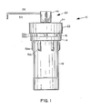
- FIG. 1 illustrates a side view of a microwave digestion vessel 10 including a Teflon PFA vessel 12 with a threaded top 13, as illustrated in FIG. 2, and a molding flange 14 for encompassing a lower portion of a Teflon PFA cap 16 with internal threads 18, as illustrated in FIG. 2.
- a valve body 20 extends upwardly from the top of the cap 16, and is described in detail in FIG. 2.
- a venting tube 54 extends outwardly from the valve cap 46 as later described.
- a retaining ring 22 with a top leading edge 24 surrounds an upper portion of the cap 16 and includes internal threads 26 as illustrated in FIG. 2.
- the ring 22 provides that cap 16 cannot expand away from the vessel 12 during microwave digestion procedures at elevated temperatures. Threads 26 are self threading providing for loose screwing of the ring 22 on and off of the cap 16 as required.
- FIG. 2 illustrates a cross-sectional view of FIG. 1 where all numerals correspond to those elements previously described.
- the valve body 20 includes a central hole 28, a ball seat 30, and narrow aperture clearance 32 upwardly extending on an interior section of an upwardly extending valve body wall 27.
- the ball seat is positioned about a lower portion of a ball 34 in the top wall of the cap 16.
- Top 36 of the valve body 20 is planar providing for a positive stop.
- the Teflon ball 34 engages against the ball seat 30.
- a Teflon spiral spring 38 engages within the internal cylindrical wall section 39 of the valve body 20.
- the Teflon spring 38 includes two open cylindrical members 40 and 42 connected by a section of spiral spring 44.
- a plurality of spacing nipples 45a-45n extend outwardly from the members 40-44.
- Each cylindrical member 40 and 42 includes a 45′ chamber or a rounded chamber, and a flat surface as later described in FIG. 3.
- a valve cap 46 includes interior threads 48 which engage with threads 29 of the valve body 47, providing for an integral fit.
- a top underside surface 47 of valve cap 46 is also planar providing for a positive stop and mating with the planar surface 36 of valve body 20.
- a hole 50 extends upwardly to a side hole 52 for venting of pressures out the side of the valve cap 46.
- a relief tube 54 can be pressed into the side hole 50 for relieving and draining residual fluids into a second container as later described.
- the Teflon spring can be glass filled, a composite, or the like, for maintaining a proper flexible spring coefficient.
- the vessel bottom, vessel cap, and valve seat and cap, as well as the ball and spring can also be made out of other materials than Teflon PFA.
- the spring section can also assume any other like geometrical configuration such as a "Z" shape, etc., rather than the spiral shape as illustrated.
- the ring 22 can be of a polymer, a composite, or other like material.
- the flange 14 is of an annular right angle shape so that the lower portion of the cap 16 screws and extends down into the area created by the encompassing annular flange so that the cap 16 will not expand off of the threaded vessel top 13 during digestion processes which create height pressures.
- the top of the vessel 12 includes a flat planar lip edge s0 with annular exterior edge 64.
- the interior of the cap 12 includes an angled annular interior wedge edge 62. As the cap 16 is screwed on tightly, angled wedge edge 62 exerts outward force upon lip edge 60 and forces it and the annular exterior edge 64 outwardly affecting a secure pressurized seal between edge 64 and the adjacent interior cap surface, as well as between wedge edge 62 and portions of lip edge 60. It is illustrated that the two planar surfaces 36 and 47 of valve body 20 and valve cap 46, respectively, mate flush with each other's surfaces.
- FIG. 3 illustrates an enlarged view of the valve body 27, ball 34, and the spring 38.
- Each open cylindrical member 40 and 42 includes a 45′ or conforming chamber 40a and 42a and a flat surface 40b and 42b. Hollow portions 40c and 42c through members 40 and 42 are provided for venting of gases, vapors, etc.
- the spring 38 is interchangeable in either direction for ease of installation.
- the spring includes a plurality of spacing nipples 45a-45n for spacing elements 40-44 from the side wall 39.
- the spring can be of one to ten turns, while two turns are illustrated by way of example and for purposes of illustration only.
- the transition from the ball seat 30 to the clearance of each side of the 34 in hole 28 is in the range of 20/1000 inch for controlling pressure release, although any other suitable dimension can be utilized as parameters would require.
- FIG. 4 illustrates a top view in partial cross section of the present invention where all numerals correspond to those elements previously described.
- a plurality of downwardly extending lugs 56a-56n are provided for the cap 16, and a plurality of like downwardly extending lugs 58a-58n are provided for the the vessel 12.
- These ribs provide point contact gripping point for a lug tool to separate the top and bottom of the vessel.
- the lower lugs 58a-58n are molded into the lower edge of flange 14 for structural integrity and stability.
- FIG. 5 illustrates a bottom view of the vessel where all numbers correspond to those elements previously described.
- FIG. 6 illustrates the mode of operation of the present invention, illustrating a microwave oven 80, and a turntable 82 in the microwave oven cavity 84 for supporting a plurality of digestion vessels 10 about the perimeter of the turntable 82.
- Two digestion vessels 86 and 88 are shown by way of example and for purposes of illustration only.
- a container 90 positions on the axis of the turntable.
- the microwave digestion vessels include relief tubes from the hole of each valve assembly coupled into the container for discharge of any residual pressure, vapors, or liquids, etc.
- the container 90 can include a cap 92.
- the container and cap can be made of Teflon, glass, or any other material transparent to microwave energy.
- the bottle, cap, and ring will be made of materials transparent to microwave energy.
- the material while indicated as a fluoropolymer, such as Teflon PFA, can include a glass fiber filler, rag content, or a composite material.
- the ring can also be made of a polymer as required.
- the vessels can be used with or without the ring as illustrated in FIG. 5 where one vessel is illustrated with the ring 22 and the other vessel is without the ring.
- FIG. 7 illustrates a side view of a first alternate embodiment of a microwave digestion vessel 100 including a vessel 102 of Teflon PFA or like material with a buttress threaded upper member lo4 as illustrated in FIG. 9.
- a molded flange 106 encompasses a lower portion of a Teflon PFA vessel cap 108 including internal buttress threads 110 as illustrated in FIG. 9, although the molded flange 106 is not required for operation in low pressure functions.
- a threaded cap neck 112 extends from the upper surface of the cap 108.
- Cap 114 fits over and about neck 112.
- a configured, angled, threaded filter body member 116 intersects with the neck 112 and the top surface of the cap or lid 108.
- a pointer member 118 positions on the upper surface of cap 108 for determining and referencing preset adjustment of the relief internal valve as described in detail in FIGS. 9 and 10.
- Lugs 109a-109n and 111a-111n, as described in previous Figures position about 28 and on cap 108 and vessel 102 for tightening of the cap 108 to the vessel 102.
- a knurled nut 120 with internal ferrels positions over and about the angled filter tube body 116 for securing a relief tube 122 to the filter body 116.
- FIG. 8 illustrates a top view of the cap or lid 108 including the smaller cap 114, the adjustment reference numbers 124, the pointer 118 for referencing adjustment numbers 124, the filter body 116, the knurled nut 120 and the relief tube 122.
- FIG. 9 illustrates an exploded view of the relief valve and outlet port of FIG. 7.
- the inner cylindrical portion 113 of threaded neck 112 and a semi-spherical cavity ball seat surface 126 in a lower portion of cap 108 form a valve cavity body 128.
- a small orifice 130 positions at the bottom of the valve cavity 128 to vent pressure from the interior of vessel 102 out through filter body tube 116 as described in later detail.
- a hole 132 positions between the vent cavity 128 and a larger hole 134 in the filter body 116 as illustrated.
- Beveled edge 136 at the outer portion of larger hole 134 accommodates a built-in integral ferrel surface 138 for positioning and securing a relief tube 122 to the filter body 116.
- a hydrophobic filter 140 at the end of relief tube 122 positions in the inner portion of larger hole 134 to relieve gas pressures and exclude liquids from exiting overboard.
- a spring cavity 142 is formed by walls of cylindrical sleeve 144.
- a solid radiused end 146 integral to the sleeve 144 positions at the end of the sleeve 144 and acts to serve as a valve when placed into cavity 128 and against valve hole 130.
- a spring 148 consisting of non-corrosive material such as being a spring coated with Teflon, a polymer material, a glass spring, a Teflon spring, or the like, positions in spring cavity 142 of the hollow sleeve 144.
- a threaded configured cap 114 similar to those in previous figures positions over and about the threaded neck 112.
- the top of threaded neck 112 forms an annular seal 115 to mate with the annular grove 119 in the inner top of cap 114.
- the spring 148 in the hollow sleeve 144 exerts downward pressure against flat sur face 145 to radiused ball valve 146, thereby affecting a pressure seal of the radiused ball valve 146 in semi-spherical cavity 126 surface and sealing against the orifice 130.
- Fine interior buttressed threads 15o mate to fine exterior buttressed threads 152 of the neck 112 providing for vernier like fine adjustment of tension on spring 148, thereby allowing for fine tuning of the pressure relief differential as vessel pressures relieve through orifice 130, against valve ball 146, through hydroscopic filter 140 in filter body 116, and overboard through relief tube 122.
- the top of vessel 102 forms an annular ring 103 and effects a seal in annular groove 105 in cap 108 as illustrated.
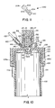
- FIG. 10 illustrates a cross-sectional assembled view of FIG. 9 where all numerals correspond to those elements previously described.
- Physical dimensions by way of example and not to be construed as limiting of the present invention include a 3/16" radius for the semi-spherical ball seat 126, a 3/8" wide spring 148, a 3/64" sleeve 144 thickness, a 3/4" diameter cap 114, a 3/32" to 1/8" orifice 130, a 1/8" diameter orifice 132, 3/16" O.D. x 1/8" I.D. tubing 122, and a threaded diameter 0.600" buttress threaded GTPI 150 and 152.
- FIG. 11 illustrates an alternative embodiment of structure for a hydrophobic vent insert 200.
- a hydrophobic vent insert 200 can in its entirety be placed within hole 134 in filter body 116 in lieu of hydrophobic filter 140.
- Configured male portion 202 mates into configured female portion 204 as illustrated.
- a small wafer like hydrophobic filter 206 is placed internally as illustrated, and gases flow between orifices 210 and 208, through the hydrophobic insert 200, and overboard through vent tube 122.
- the gas vents out during predigestion, allowing excess gas to escape without loosing any liquids inside the container.
- the adjustable nut allows for dialing in any predetermined pressure for different digestion procedures. A user can also open the adjustment nut before removing the main cap, allowing for the exhausting of any built-up pressure through the vent.
- the spring can be reused, or in the event that the spring has experienced fatigue, the spring can also be exchanged.
- the thin sleeve protects the spring from hot gases during a digestion procedure, as the gases vent in a least distance path, and does not pass by the spring.
- the area for the porous plug or permeable membrane allows for gases to vent as safely as possible.
- the permeable membrane could be as thin as 10ml in any type of suitable microporous or filtering material.
- a two-piece assembly may also be utilized as illustrated in FIG. 11 for containing a thin disc or discs, such as for a hydrophobic vent.
- the springs can be made of any suitable materials, such as special alloys, Teflon coated, glass springs, glass-reinforced polymers, polymers or Teflon springs.
- the hole 130 can be varied in diameter which would vary to release pressure at a desired level.
- the spring compression is adjustable by the number of turns, diameter of the cross-section, etc., and any space between the top of the cap and the top of the sleeve 144 is adjustable.
- the sleeve 144 is a one-piece member. During digestion, the sleeve rises to allow gases to escape, but not liquids under digestion, as indicated by dashed line "P" in FIG. 10.
- An external filter could be used in lieu of the assemblies 140 and 200 of FIGS. 10 and 11.
- the spring can be of Teflon, a coated metal, ceramic, or any other suitable material.
- the disk or membrane is a porous material, and relieves the pressure differential accordingly.
Landscapes
- Chemical & Material Sciences (AREA)
- Physics & Mathematics (AREA)
- Electromagnetism (AREA)
- Health & Medical Sciences (AREA)
- General Health & Medical Sciences (AREA)
- Life Sciences & Earth Sciences (AREA)
- Organic Chemistry (AREA)
- Chemical Kinetics & Catalysis (AREA)
- Toxicology (AREA)
- Analytical Chemistry (AREA)
- Biochemistry (AREA)
- General Physics & Mathematics (AREA)
- Immunology (AREA)
- Pathology (AREA)
- Pressure Vessels And Lids Thereof (AREA)
- Safety Valves (AREA)
- Cookers (AREA)
Applications Claiming Priority (1)
| Application Number | Priority Date | Filing Date | Title |
|---|---|---|---|
| US06/702,639 US4613738A (en) | 1985-02-19 | 1985-02-19 | Microwave heating digestion vessel |
Publications (1)
| Publication Number | Publication Date |
|---|---|
| EP0335020A1 true EP0335020A1 (de) | 1989-10-04 |
Family
ID=24822047
Family Applications (1)
| Application Number | Title | Priority Date | Filing Date |
|---|---|---|---|
| EP88302857A Withdrawn EP0335020A1 (de) | 1985-02-19 | 1988-03-30 | Verdauungsbehälter für Mikrowellenofen |
Country Status (2)
| Country | Link |
|---|---|
| US (1) | US4613738A (de) |
| EP (1) | EP0335020A1 (de) |
Cited By (7)
| Publication number | Priority date | Publication date | Assignee | Title |
|---|---|---|---|---|
| EP0427113A1 (de) * | 1989-10-31 | 1991-05-15 | Inwave Ag Industrie Mikrowellentechnik | Mikrowellenofen mit Einsatz |
| EP0429814A3 (en) * | 1989-10-11 | 1991-10-16 | Mls Gmbh | Process and apparatus for initiating and/or promoting chemical processes |
| EP0467625A3 (en) * | 1990-07-19 | 1992-08-05 | Cem Corporation | Temperature controlled microwave system for heating contents of sealed moving containers |
| WO1993022650A3 (de) * | 1992-04-30 | 1993-12-23 | Mikrowellen Labor Systeme | Vorrichtung zur verdampfungsbehandlung von vorzugsweise flüssigen stoffen, insbesondere reagenzstoffen, oder zum aufbereiten oder analysieren von probenmaterial |
| WO2000072957A1 (en) * | 1999-06-01 | 2000-12-07 | Cem Corporation | Sealing closure for high pressure vessels in microwave assisted chemistry |
| EP1547681A3 (de) * | 2003-09-02 | 2005-09-07 | CEM Corporation | Durchflussgeregeltes Gerät für ein mikrowellenunterstütztes chemisches Verfahren |
| US7041947B2 (en) | 2003-09-02 | 2006-05-09 | Cem Corporation | Controlled flow instrument for microwave assisted chemistry with high viscosity liquids and heterogeneous mixtures |
Families Citing this family (34)
| Publication number | Priority date | Publication date | Assignee | Title |
|---|---|---|---|---|
| US4613738A (en) * | 1985-02-19 | 1986-09-23 | Savillex | Microwave heating digestion vessel |
| US4736083A (en) * | 1985-02-19 | 1988-04-05 | Savillex Corporation | Microwave heating digestion vessel |
| US4877624A (en) * | 1985-04-11 | 1989-10-31 | Cem Corporation | Digestion and sterilization methods and apparatus |
| US4882128A (en) * | 1987-07-31 | 1989-11-21 | Parr Instrument Company | Pressure and temperature reaction vessel, method, and apparatus |
| US4801773A (en) * | 1987-10-01 | 1989-01-31 | Ronnie Hanlon | Shroud to cover dish in microwave oven |
| DE3839901A1 (de) * | 1988-11-25 | 1990-05-31 | Werner Lautenschlaeger | Probenbehaelter zum aufschliessen von probenmaterial |
| EP0382334A3 (de) * | 1989-02-09 | 1991-09-18 | Bio-Rad Laboratories, Inc. | Verfahren zur Herstellung von Serumproben für Vitamin B12 und Folate-Analyse unter Verwendung von Mikrowellen |
| US4904450A (en) * | 1989-03-01 | 1990-02-27 | Terry Floyd | High temperature and high pressure digestion vessel assembly |
| US5204065A (en) * | 1989-03-01 | 1993-04-20 | Terry Floyd | High pressure and high temperature digestion vessel |
| US5264185A (en) * | 1989-03-01 | 1993-11-23 | Floyd Terry S | High pressure and high temperature digestion vessel |
| US4933529A (en) * | 1989-04-03 | 1990-06-12 | Savillex Corporation | Microwave heating digestion vessel |
| US5108701A (en) * | 1989-05-15 | 1992-04-28 | Cem Corporation | Process for rapid sterilization of biological media |
| US5320804A (en) * | 1989-05-15 | 1994-06-14 | Cem Corporation | Process and apparatus for controlled microwave heating under pressure |
| US5230865A (en) * | 1989-09-08 | 1993-07-27 | Cem Corporation | Ventable rupture diaphragm-protected container for heating contained materials by microwave radiation |
| US5206479A (en) * | 1990-05-04 | 1993-04-27 | Cem Corporation | Microwave heating system |
| US5407641A (en) * | 1990-10-25 | 1995-04-18 | Helmut Katschnig | Microwave apparatus, and container for use in a microwave apparatus |
| DE4108766C2 (de) * | 1991-03-18 | 1996-08-01 | Knapp Guenter Univ Prof Dipl I | Vorrichtung zum Erhitzen von Substanzen unter Entstehung hoher Drücke im Mikrowellenfeld |
| CA2093996C (en) * | 1992-05-04 | 2005-01-11 | Bobby Earl Green | Microwaveable squeeze bottle for cheese sauce and the like |
| US20020198230A1 (en) * | 1993-09-24 | 2002-12-26 | Howard M. Kingston | Method and apparatus for microwave assisted chemical reactions |
| DE4413425B4 (de) * | 1994-04-18 | 2006-08-31 | Anton Paar Gmbh | Vorrichtung zur Überwachung des Drucks in mehreren Aufschlußgefäßen |
| US5948307A (en) * | 1997-06-04 | 1999-09-07 | O.I. Corporation | High pressure relief for microwave digestion vessel assembly |
| US6803237B2 (en) | 2000-01-25 | 2004-10-12 | Woods Hole Oceanographic Institution | Sequential processing reaction vessel for chemical fractionation and analysis |
| JP3375930B2 (ja) * | 2000-03-06 | 2003-02-10 | 日本ピラー工業株式会社 | チェックバルブ |
| DE10050085C1 (de) * | 2000-10-10 | 2001-10-31 | Jochem Koetting | Verschlußelement und Verschlußsystem für Behältnisse und Gefäße |
| US20030194352A1 (en) * | 2001-12-20 | 2003-10-16 | Milestone S.R.L. | Device for closing a plurality of digestion vessesls |
| DE20120649U1 (de) * | 2001-12-20 | 2002-04-18 | MLS Mikrowellen-Labor-Systeme GmbH, 88299 Leutkirch | Vorrichtung zum Verschließen eines topfförmigen Aufschlussbehälters |
| US20030127313A1 (en) * | 2001-12-20 | 2003-07-10 | Milestone S.R.L. | Device for closing a pot-like digestion vessel |
| US7311118B2 (en) * | 2004-03-30 | 2007-12-25 | Parker-Hannifin Corporation | Floating ball check valve |
| US7820944B2 (en) * | 2006-05-08 | 2010-10-26 | Lincoln Global, Inc. | Spectroscopic technique for measuring the composition of cored wire electrodes |
| WO2009126099A1 (en) * | 2008-04-10 | 2009-10-15 | Denator Aktiebolag | Device for storing a biological sample and for preparing the biological sample |
| ITRM20110140U1 (it) * | 2011-09-08 | 2013-03-09 | Etatron D S Spa | Valvola di iniezione equipaggiata con molla in materiale plastico pvdf, utilizzata quale accessorio di pompe dosatrici elettromeccaniche |
| CN104056584B (zh) * | 2014-05-23 | 2016-03-02 | 上海屹尧仪器科技发展有限公司 | 可适用于微波工作环境的自卸压式化学反应釜 |
| US10065168B2 (en) | 2016-05-02 | 2018-09-04 | Cem Corporation | High temperature pressure digestion vessel system with dual action seal |
| CN108709790B (zh) * | 2018-05-02 | 2021-01-22 | 佛山市高明区杨和金属材料专业镇技术创新中心 | 一种微波消解仪的排气装置 |
Citations (3)
| Publication number | Priority date | Publication date | Assignee | Title |
|---|---|---|---|---|
| FR2417045A1 (fr) * | 1978-02-14 | 1979-09-07 | Accumulateurs Fixes | Soupape de surete |
| US4490597A (en) * | 1979-09-19 | 1984-12-25 | Mengel Clare L | Microwave permeable pressure compensating container |
| US4613738A (en) * | 1985-02-19 | 1986-09-23 | Savillex | Microwave heating digestion vessel |
Family Cites Families (6)
| Publication number | Priority date | Publication date | Assignee | Title |
|---|---|---|---|---|
| US2226593A (en) * | 1940-12-31 | Pressure cooker | ||
| US2826218A (en) * | 1953-10-02 | 1958-03-11 | Sidney D Barlow | Valve construction |
| US4343325A (en) * | 1977-09-28 | 1982-08-10 | Draft Systems, Inc. | Valve assembly and coupler therefor |
| US4254319A (en) * | 1979-06-25 | 1981-03-03 | Bruce Beh | Portable microwave oven-turntable device |
| US4406861A (en) * | 1980-02-19 | 1983-09-27 | Beauvais Max P | Microwave canning apparatus |
| ZA812894B (en) * | 1980-05-13 | 1982-05-26 | Thorn Cascade Co Ltd | Appliance for making an aerated beverage and a cap for a bottle used therein |
-
1985
- 1985-02-19 US US06/702,639 patent/US4613738A/en not_active Expired - Fee Related
-
1988
- 1988-03-30 EP EP88302857A patent/EP0335020A1/de not_active Withdrawn
Patent Citations (3)
| Publication number | Priority date | Publication date | Assignee | Title |
|---|---|---|---|---|
| FR2417045A1 (fr) * | 1978-02-14 | 1979-09-07 | Accumulateurs Fixes | Soupape de surete |
| US4490597A (en) * | 1979-09-19 | 1984-12-25 | Mengel Clare L | Microwave permeable pressure compensating container |
| US4613738A (en) * | 1985-02-19 | 1986-09-23 | Savillex | Microwave heating digestion vessel |
Non-Patent Citations (1)
| Title |
|---|
| SOVIET INVENTIONS ILLUSTRATED * |
Cited By (12)
| Publication number | Priority date | Publication date | Assignee | Title |
|---|---|---|---|---|
| EP0429814A3 (en) * | 1989-10-11 | 1991-10-16 | Mls Gmbh | Process and apparatus for initiating and/or promoting chemical processes |
| EP0427113A1 (de) * | 1989-10-31 | 1991-05-15 | Inwave Ag Industrie Mikrowellentechnik | Mikrowellenofen mit Einsatz |
| EP0467625A3 (en) * | 1990-07-19 | 1992-08-05 | Cem Corporation | Temperature controlled microwave system for heating contents of sealed moving containers |
| WO1993022650A3 (de) * | 1992-04-30 | 1993-12-23 | Mikrowellen Labor Systeme | Vorrichtung zur verdampfungsbehandlung von vorzugsweise flüssigen stoffen, insbesondere reagenzstoffen, oder zum aufbereiten oder analysieren von probenmaterial |
| US5447077A (en) * | 1992-04-30 | 1995-09-05 | Mls Mikrowellen-Labor-Systeme Gmbh | Device for the evaporation treatment of preferably liquid substances, in particular reagents, or for the preparation or analysis of sample material |
| WO2000072957A1 (en) * | 1999-06-01 | 2000-12-07 | Cem Corporation | Sealing closure for high pressure vessels in microwave assisted chemistry |
| US6287526B1 (en) | 1999-06-01 | 2001-09-11 | Cem Corporation | Sealing closure for high pressure vessels in microwave assisted chemistry |
| US6863871B2 (en) | 1999-06-01 | 2005-03-08 | Cem Corporation | Sealing closure for high pressure vessels in microwave assisted chemistry |
| EP1547681A3 (de) * | 2003-09-02 | 2005-09-07 | CEM Corporation | Durchflussgeregeltes Gerät für ein mikrowellenunterstütztes chemisches Verfahren |
| US7041947B2 (en) | 2003-09-02 | 2006-05-09 | Cem Corporation | Controlled flow instrument for microwave assisted chemistry with high viscosity liquids and heterogeneous mixtures |
| US7109452B2 (en) | 2003-09-02 | 2006-09-19 | Cem Corporation | Controlled flow instrument for microwave assisted chemistry with high viscosity liquids and heterogeneous mixtures |
| US7214913B2 (en) | 2003-09-02 | 2007-05-08 | Cem, Corporation | Controlled flow instrument for microwave assisted chemistry with high viscosity liquids and heterogeneous mixtures |
Also Published As
| Publication number | Publication date |
|---|---|
| US4613738A (en) | 1986-09-23 |
Similar Documents
| Publication | Publication Date | Title |
|---|---|---|
| EP0335020A1 (de) | Verdauungsbehälter für Mikrowellenofen | |
| US4736083A (en) | Microwave heating digestion vessel | |
| US4933529A (en) | Microwave heating digestion vessel | |
| US5264185A (en) | High pressure and high temperature digestion vessel | |
| US5204065A (en) | High pressure and high temperature digestion vessel | |
| US4904450A (en) | High temperature and high pressure digestion vessel assembly | |
| US5353949A (en) | Vent filter assembly | |
| US6076471A (en) | Tank car manway cover assembly | |
| US5270010A (en) | Sample holder for decomposition or analysis of sample materials | |
| KR100386001B1 (ko) | 축전지 배터리 내에 생성된 연기를 배출시키는 장치 | |
| GB1564483A (en) | Pressure cookers | |
| KR20130091697A (ko) | 압력 쿠커용 압력 릴리스 밸브 어셈블리 | |
| US4402828A (en) | Pressure filter vessel | |
| US5948307A (en) | High pressure relief for microwave digestion vessel assembly | |
| JPH03111263A (ja) | ねじ蓋封鎖体を備えた容器 | |
| FI69959C (fi) | Lock | |
| US5911332A (en) | HEPA filtered storage canisters | |
| CN102901663B (zh) | 新型密闭微波消解罐 | |
| US6948515B2 (en) | Carbon rupture disk assembly | |
| CA1074464A (en) | Top closure for control rod drive for nuclear reactor | |
| US4909408A (en) | Venting system for beverage containers | |
| JPH01274382A (ja) | マイクロ波加熱蒸解容器 | |
| KR100536639B1 (ko) | 압력 쿠커의 압력해제 밸브를 위한 안전캡과 이를사용하는 압력 쿠커 | |
| US7048139B1 (en) | Corrosion resistant vents with integral filter | |
| DK150423B (da) | Taerelement med luftdepolarisation |
Legal Events
| Date | Code | Title | Description |
|---|---|---|---|
| PUAI | Public reference made under article 153(3) epc to a published international application that has entered the european phase |
Free format text: ORIGINAL CODE: 0009012 |
|
| AK | Designated contracting states |
Kind code of ref document: A1 Designated state(s): DE FR GB |
|
| STAA | Information on the status of an ep patent application or granted ep patent |
Free format text: STATUS: THE APPLICATION IS DEEMED TO BE WITHDRAWN |
|
| 18D | Application deemed to be withdrawn |
Effective date: 19900405 |