EP0334774A1 - Integrierte Vorrichtung zur biospezifischen Reinigung einer Zellen enthaltenden Flüssigkeit - Google Patents
Integrierte Vorrichtung zur biospezifischen Reinigung einer Zellen enthaltenden Flüssigkeit Download PDFInfo
- Publication number
- EP0334774A1 EP0334774A1 EP89420088A EP89420088A EP0334774A1 EP 0334774 A1 EP0334774 A1 EP 0334774A1 EP 89420088 A EP89420088 A EP 89420088A EP 89420088 A EP89420088 A EP 89420088A EP 0334774 A1 EP0334774 A1 EP 0334774A1
- Authority
- EP
- European Patent Office
- Prior art keywords
- liquid
- membrane
- purification
- treated
- biospecific
- Prior art date
- Legal status (The legal status is an assumption and is not a legal conclusion. Google has not performed a legal analysis and makes no representation as to the accuracy of the status listed.)
- Granted
Links
- 239000007788 liquid Substances 0.000 title claims abstract description 174
- 239000012528 membrane Substances 0.000 claims abstract description 101
- 238000000746 purification Methods 0.000 claims abstract description 90
- 238000001914 filtration Methods 0.000 claims abstract description 75
- 230000001413 cellular effect Effects 0.000 claims description 46
- 239000012510 hollow fiber Substances 0.000 claims description 34
- 230000004087 circulation Effects 0.000 claims description 16
- 239000012982 microporous membrane Substances 0.000 claims description 6
- 210000004369 blood Anatomy 0.000 abstract description 45
- 239000008280 blood Substances 0.000 abstract description 45
- 238000000926 separation method Methods 0.000 abstract description 6
- 238000002616 plasmapheresis Methods 0.000 abstract description 4
- 210000002381 plasma Anatomy 0.000 description 26
- 238000009826 distribution Methods 0.000 description 11
- 230000002093 peripheral effect Effects 0.000 description 11
- 239000000835 fiber Substances 0.000 description 8
- 239000000126 substance Substances 0.000 description 7
- 238000004804 winding Methods 0.000 description 6
- 210000004027 cell Anatomy 0.000 description 4
- 238000004382 potting Methods 0.000 description 4
- 102000004169 proteins and genes Human genes 0.000 description 4
- 108090000623 proteins and genes Proteins 0.000 description 4
- 210000000601 blood cell Anatomy 0.000 description 3
- 239000003795 chemical substances by application Substances 0.000 description 3
- 238000004519 manufacturing process Methods 0.000 description 3
- 238000000034 method Methods 0.000 description 3
- 229920002635 polyurethane Polymers 0.000 description 3
- 239000004814 polyurethane Substances 0.000 description 3
- 238000007789 sealing Methods 0.000 description 3
- 241000894006 Bacteria Species 0.000 description 2
- 239000013543 active substance Substances 0.000 description 2
- 239000000853 adhesive Substances 0.000 description 2
- 230000001070 adhesive effect Effects 0.000 description 2
- 238000004891 communication Methods 0.000 description 2
- 239000004744 fabric Substances 0.000 description 2
- 238000010079 rubber tapping Methods 0.000 description 2
- 102000003886 Glycoproteins Human genes 0.000 description 1
- 108090000288 Glycoproteins Proteins 0.000 description 1
- 206010018910 Haemolysis Diseases 0.000 description 1
- QPMSXSBEVQLBIL-CZRHPSIPSA-N ac1mix0p Chemical compound C1=CC=C2N(C[C@H](C)CN(C)C)C3=CC(OC)=CC=C3SC2=C1.O([C@H]1[C@]2(OC)C=CC34C[C@@H]2[C@](C)(O)CCC)C2=C5[C@]41CCN(C)[C@@H]3CC5=CC=C2O QPMSXSBEVQLBIL-CZRHPSIPSA-N 0.000 description 1
- XECAHXYUAAWDEL-UHFFFAOYSA-N acrylonitrile butadiene styrene Chemical compound C=CC=C.C=CC#N.C=CC1=CC=CC=C1 XECAHXYUAAWDEL-UHFFFAOYSA-N 0.000 description 1
- 229920000122 acrylonitrile butadiene styrene Polymers 0.000 description 1
- 239000004676 acrylonitrile butadiene styrene Substances 0.000 description 1
- 238000004026 adhesive bonding Methods 0.000 description 1
- 150000001413 amino acids Chemical class 0.000 description 1
- 230000015572 biosynthetic process Effects 0.000 description 1
- 230000017531 blood circulation Effects 0.000 description 1
- 230000015556 catabolic process Effects 0.000 description 1
- 239000006285 cell suspension Substances 0.000 description 1
- 125000003636 chemical group Chemical group 0.000 description 1
- 238000005056 compaction Methods 0.000 description 1
- 230000000295 complement effect Effects 0.000 description 1
- 230000006378 damage Effects 0.000 description 1
- 230000007423 decrease Effects 0.000 description 1
- 238000006731 degradation reaction Methods 0.000 description 1
- 238000000502 dialysis Methods 0.000 description 1
- 238000007599 discharging Methods 0.000 description 1
- 210000003743 erythrocyte Anatomy 0.000 description 1
- 239000003292 glue Substances 0.000 description 1
- 150000004676 glycans Chemical class 0.000 description 1
- 230000008588 hemolysis Effects 0.000 description 1
- 238000012423 maintenance Methods 0.000 description 1
- 239000000463 material Substances 0.000 description 1
- 238000005374 membrane filtration Methods 0.000 description 1
- 230000007170 pathology Effects 0.000 description 1
- 238000009832 plasma treatment Methods 0.000 description 1
- 229920000515 polycarbonate Polymers 0.000 description 1
- 239000004417 polycarbonate Substances 0.000 description 1
- 229920000728 polyester Polymers 0.000 description 1
- 229920001282 polysaccharide Polymers 0.000 description 1
- 239000005017 polysaccharide Substances 0.000 description 1
- 239000004800 polyvinyl chloride Substances 0.000 description 1
- 229920000915 polyvinyl chloride Polymers 0.000 description 1
- 239000011148 porous material Substances 0.000 description 1
- 238000005215 recombination Methods 0.000 description 1
- 230000006798 recombination Effects 0.000 description 1
- 239000011347 resin Substances 0.000 description 1
- 229920005989 resin Polymers 0.000 description 1
- 230000000717 retained effect Effects 0.000 description 1
- 239000007787 solid Substances 0.000 description 1
- 239000000725 suspension Substances 0.000 description 1
- 238000003856 thermoforming Methods 0.000 description 1
- 238000002604 ultrasonography Methods 0.000 description 1
- 239000011800 void material Substances 0.000 description 1
- 238000003466 welding Methods 0.000 description 1
Images


Classifications
-
- B—PERFORMING OPERATIONS; TRANSPORTING
- B01—PHYSICAL OR CHEMICAL PROCESSES OR APPARATUS IN GENERAL
- B01D—SEPARATION
- B01D63/00—Apparatus in general for separation processes using semi-permeable membranes
- B01D63/08—Flat membrane modules
- B01D63/087—Single membrane modules
-
- A—HUMAN NECESSITIES
- A61—MEDICAL OR VETERINARY SCIENCE; HYGIENE
- A61M—DEVICES FOR INTRODUCING MEDIA INTO, OR ONTO, THE BODY; DEVICES FOR TRANSDUCING BODY MEDIA OR FOR TAKING MEDIA FROM THE BODY; DEVICES FOR PRODUCING OR ENDING SLEEP OR STUPOR
- A61M1/00—Suction or pumping devices for medical purposes; Devices for carrying-off, for treatment of, or for carrying-over, body-liquids; Drainage systems
- A61M1/34—Filtering material out of the blood by passing it through a membrane, i.e. hemofiltration or diafiltration
- A61M1/3472—Filtering material out of the blood by passing it through a membrane, i.e. hemofiltration or diafiltration with treatment of the filtrate
- A61M1/3475—Filtering material out of the blood by passing it through a membrane, i.e. hemofiltration or diafiltration with treatment of the filtrate with filtrate treatment agent in the same enclosure as the membrane
-
- A—HUMAN NECESSITIES
- A61—MEDICAL OR VETERINARY SCIENCE; HYGIENE
- A61M—DEVICES FOR INTRODUCING MEDIA INTO, OR ONTO, THE BODY; DEVICES FOR TRANSDUCING BODY MEDIA OR FOR TAKING MEDIA FROM THE BODY; DEVICES FOR PRODUCING OR ENDING SLEEP OR STUPOR
- A61M1/00—Suction or pumping devices for medical purposes; Devices for carrying-off, for treatment of, or for carrying-over, body-liquids; Drainage systems
- A61M1/34—Filtering material out of the blood by passing it through a membrane, i.e. hemofiltration or diafiltration
- A61M1/3472—Filtering material out of the blood by passing it through a membrane, i.e. hemofiltration or diafiltration with treatment of the filtrate
- A61M1/3486—Biological, chemical treatment, e.g. chemical precipitation; treatment by absorbents
- A61M1/3489—Biological, chemical treatment, e.g. chemical precipitation; treatment by absorbents by biological cells, e.g. bioreactor
-
- B—PERFORMING OPERATIONS; TRANSPORTING
- B01—PHYSICAL OR CHEMICAL PROCESSES OR APPARATUS IN GENERAL
- B01D—SEPARATION
- B01D61/00—Processes of separation using semi-permeable membranes, e.g. dialysis, osmosis or ultrafiltration; Apparatus, accessories or auxiliary operations specially adapted therefor
- B01D61/14—Ultrafiltration; Microfiltration
- B01D61/18—Apparatus therefor
-
- A—HUMAN NECESSITIES
- A61—MEDICAL OR VETERINARY SCIENCE; HYGIENE
- A61M—DEVICES FOR INTRODUCING MEDIA INTO, OR ONTO, THE BODY; DEVICES FOR TRANSDUCING BODY MEDIA OR FOR TAKING MEDIA FROM THE BODY; DEVICES FOR PRODUCING OR ENDING SLEEP OR STUPOR
- A61M1/00—Suction or pumping devices for medical purposes; Devices for carrying-off, for treatment of, or for carrying-over, body-liquids; Drainage systems
- A61M1/36—Other treatment of blood in a by-pass of the natural circulatory system, e.g. temperature adaptation, irradiation ; Extra-corporeal blood circuits
- A61M1/3687—Chemical treatment
Definitions
- the present invention relates to the technical field of the treatment of biological liquids to rid them of undesirable substances contained therein. More particularly, the present invention relates to a device for the filtration and biospecific purification of a biological liquid, in particular blood.
- French patent application 2,035,134 thus proposes a device making it possible to remove proteins or amino acids determined from the blood by passage over an active substance.
- Such a device presents a risk of degradation of the figured elements of the blood and in particular of the erythrocytes. Hemolysis following treatment of blood in this way is therefore the major drawback of such a technique.
- this patent application proposes a blood treatment system comprising a first device for separating the plasma from the figured elements of the blood, then in series, a second device for purifying the plasma.
- a blood treatment system comprising a first device for separating the plasma from the figured elements of the blood, then in series, a second device for purifying the plasma.
- the plasma retrofilters to join the enriched blood. in figurative elements.
- the plasma obtained by filtration of blood through the semi-permeable membrane constituting the wall of the hollow fibers is treated with an agent contained in the treatment chamber; thus, at the exit of this device, one obtains a recombination of the figured elements of the blood with the purified plasma.
- this device overcomes a number of drawbacks of the prior art, it has the disadvantage of being limited by the rate of plasmafiltration through the semi-permeable membrane. Indeed, to be able to use the filtration and retrofiltration processes, the pressure difference on either side of the plasmapheresis membrane must be canceled at the center of the module, which then results in a zero filtration flow rate at this point. To increase the overall flow rate of plasmafiltration, it would be necessary to be able to increase the filtration area, the flow rate of the blood to be treated or the pressure drop in the blood inside the device. Given its limited filtration capacity, such a device therefore does not meet the current performance requirements.
- the purification device further comprises means for subjecting the blood to be purified to pressure variations so as to cause an alternating passage of a fraction of the blood through the micropores of the membrane.
- the plasma fraction of the blood to be purified penetrates through the micropores of the membrane and comes into contact with biologically active substances.
- Such a device therefore makes it possible to avoid the preliminary phase of plasmafiltration while avoiding contact between the blood cells of the blood and the active biological substances.
- such a device presents serious manufacturing difficulties.
- it seems difficult, with such a device to achieve a sufficient purification rate.
- biospecific purification devices of the prior art do not make it possible to carry out the treatment of a biological liquid, in particular blood, in a satisfactory manner.
- the object of the present invention is to provide a biospecific purification device which does not have the drawbacks of the prior art and which allows good purification of a biological liquid, in particular blood, without the risk of cell destruction.
- Another object of the present invention is to provide a biospecific purification device, not requiring a large volume of liquid in circulation.
- Another object of the present invention is to provide a biospecific purification device, the manufacture of which can be carried out easily and at low cost prices.
- Another object of the present invention is to provide a biospecific purification device having good efficiency with respect to the size and the bulk of the device.
- Another object of the present invention is to provide a biospecific purification device, the implementation of which is simple, reliable and has all the security necessary for the patient during treatment.
- the present invention provides a device for the biospecific purification of a liquid containing cellular elements, of the type comprising a box provided with at least one inlet pipe for the liquid to be treated and inside which is arranged at least one membrane for separating by tangential filtration the liquid fraction of the cellular elements from the liquid to be treated, characterized in that said casing further comprises at least one microporous structure for biospecific purification by transverse filtration of the liquid fraction of said liquid to be treated and in that said housing is further provided with at least one outlet pipe for the liquid concentrated in cellular elements and one outlet pipe for the purified liquid fraction.
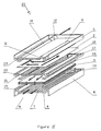
- the purification device represented as a whole by the reference 1 is essentially constituted by a flat membrane 2 for filtration of the liquid to be treated, and by a microporous structure 3 constituted by a stack of flat biospecific purification membranes.
- This set of membranes is placed inside an enclosure consisting essentially of a lower plate 4 and an upper plate 5.
- the lower plate 4 has, at the periphery, an elevation 6 constituting the side walls of the purification device 1.
- the internal face of this lower plate 4 is further provided with longitudinal grooves or any other appropriate network of grooves, constituted for example by sinusoidal grooves or continuous or discontinuous zig-zags, intended to promote the collection and circulation of the liquid obtained after filtration through all of the membranes.
- This network of grooves defines a useful zone 7 for the circulation of the purified liquid.
- a transverse pipe 105 makes it possible to collect the purified liquid.
- the lower plate 4 is also provided with a pipe 8 for communication with the outside constituting the outlet for the purified liquid; this pipe 8 is advantageously formed in the side wall 6 at one of the ends of the useful area 7.
- the upper plate 5 is provided with two lateral pipes 9 and 10 extending longitudinally and substantially parallel; these pipes 9 and 10 are respectively intended for the distribution of the liquid to be treated and for the collection of the liquid concentrated in cellular elements; they communicate with the outside through openings constituting, on the one hand the inlet 11 of the liquid to be treated and on the other hand, the outlet 12 of the liquid concentrated in cellular elements.
- the opening 11 is located on an edge of the plate 5 opposite the edge on which the opening 12 is located. This arrangement makes it possible to ensure good circulation of the liquid to be treated by avoiding the formation of a stagnation zone called " dead zone ".
- the profile of the pipes 9 and 10 is such that their section decreases substantially constantly from the openings 11 and 12. This is intended to promote the distribution of the liquid to be treated by maintaining a substantially constant speed throughout each of the pipes.
- the upper plate 5 is provided on its internal face with ribs or stops (not shown) arranged at regular intervals. Thanks to tightening at constant pressure during assembly of the device, these ribs or stops make it possible to ensure, between the upper plate 5 and the filtration membrane 2, a substantially constant spacing over the entire surface of the membrane.
- the filtration membrane 2 is a flat membrane allowing separate, by tangential filtration, the cellular elements from the liquid to be purified.
- this filtration membrane 2 is for example, a plasmapheresis membrane ensuring the separation of the plasma from the cells of the blood.
- An example of a membrane which is particularly suitable is the membrane manufactured by RHONE-POULENC bearing the name TPC 19 and the manufacturing method of which is described in the French patent application registered under number 82/00485.
- the microporous structure 3 for biospecific purification consists for example of a set of microporous flat membranes treated in an appropriate manner to ensure the biospecific purification of the liquid obtained by tangential filtration along the membrane 2.
- These are membranes having reactive chemical groups allowing the grafting of purifying molecules, constituted for example by proteins, glycoproteins, polysaccharides or more generally by organic derivatives of natural origin, synthetic or semi-synthetic having a biospecific affinity for the derivatives to be purified .
- microporous structure necessary for ensuring the biospecific purification can also be obtained by any suitable means, for example by using a sheet of nonwoven material with a high void content or by compaction of fibers or balls, or even by assembling son.
- the arrangement of the various elements constituting the purification device 1 is as follows.
- the microporous structure 3 constituted by the stack of purification membranes is arranged on the lower plate 4 inside the enclosure limited by the raised edges 6.
- the seal between the lower plate 4 and this stack is ensured by a frame seal 13.
- this stack of purification membranes a filtration membrane 2 intended to separate by tangential filtration the cellular elements of the liquid to be purified, such as, for example, the blood cells of the plasma in the case where the liquid to be purified is blood.
- the tightness of this membrane with the upper plate 5 is ensured by a frame seal 14, which is advantageously of the same type as the seal 13.
- These seals can be replaced by any equivalent means such as potting the membranes with, for example, a polyurethane adhesive.
- assembly studs 15 are distributed over the raised edges 6 of the lower plate 4. These pins 15 are intended to be introduced into the corresponding holes 16 located on the periphery of the upper plate 5. It will thus be possible to fix the purification device by riveting by ultrasound or by thermoforming for example.
- the purification device 1 thus makes it possible to integrate in a single housing a membrane for filtering the liquid to be purified as well as a microporous biospecific purification structure.
- the operation of the purification device 1 is as follows.
- the liquid to be treated is introduced into the line 9 through the inlet 11.
- This line 9 makes it possible to distribute the liquid to be treated over the entire length of the upper plate 5.
- This liquid is distributed then in the form of a film between the inlet pipe 9 and the outlet pipe 10.
- the direction of circulation of the liquid is indicated in FIG. I by arrows.
- This circulation of the liquid to be treated in the form of a film makes it possible to separate certain elements of the liquid by tangential filtration along the filtration membrane 2.
- the tangential filtration of the blood along a plasmapheresis membrane 2 makes it possible to separate the blood plasma which crosses the membrane from the cellular elements which, due to their size, are retained and are evacuated outside the device by the pipe 10 and the outlet 12.
- the liquid obtained after filtration through the membrane 2 is then filtered, but in this step by transverse filtration, through the stack of purification membranes, that is to say that all the liquid to be purified crosses the structure microporous represented by the stack of purification membranes.
- the purifying molecules grafted on the surface and in the micropores of the purification membranes selectively retain, during the transverse passage of the liquid to be purified, the molecules which it is desired to eliminate.
- the liquid thus purified is collected on the lower plate 4 by virtue of the network of grooves 7 before being evacuated outside by the outlet 8.
- the plasma obtained after tangential filtration along the membrane 2 is purified by transverse filtration through the purifying membranes.
- the purified plasma is evacuated outside the device by outlet 8. This plasma can optionally be recombined with the cellular elements coming from outlet 12, to then be returned to the patient during treatment, if the blood to be treated comes from the extracorporeal circulation of a patient.
- the device 1 it is possible to integrate in a single box the treatment of a liquid firstly by tangential filtration and then immediately by transverse filtration.
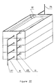
- the purification device designated as a whole by the reference 20 comprises between the filtration membrane 2 and the microporous structure 3 an intermediate plate 17.
- This intermediate plate constitutes a support for the filtration membrane 2, and therefore makes it possible to ensure a substantially constant spacing between the upper plate 5 and the filtration membrane 2, even in the case where one performs the assembly of the device at constant dimension, which from a practical point of view is preferable to an assembly at constant pressure.
- the film of liquid to be treated which flows between the inlet pipe 9 and the outlet pipe 10 has a substantially constant thickness over its entire surface.
- the intermediate plate 17 is provided on each of its two main faces, with grooves, defining, in the same way as the network of grooves on the internal face of the lower plate 4, a useful area for the circulation of the filtered liquid to be purified.
- a passage 18 allowing the filtered liquid collected on one of the faces of the intermediate plate 17 to be distributed along the other face of the plate before being purified by transverse filtration through the microporous structure 3 formed by the stack of microporous membranes.
- the elevation 6 of the lower plate 4 is provided, not with assembly studs 15 like the purification device 1 but with a peripheral groove 19 intended to receive a corresponding projection 21 situated on the periphery of the lower face of the intermediate plate 17.
- the intermediate plate 17 has on its upper face a peripheral groove 22 intended to receive a corresponding projection 23 situated on the periphery of the lower face of the lower plate 5.
- connection between the projection and the groove can be carried out by gluing or by welding, for example thermal or ultrasonic. It is also possible to assemble the device by any other appropriate means, for example by using side plates (not shown) provided with dovetail flanges which would keep all the elements of the device in contact.
- peripheral planar joints 13 and 24 located on either side of the stack of membranes 3 are intended both to ensure the tightness of the device 20 and to maintain sufficient space for the circulation of the liquid.
- the operation of the purification device 20 as shown in Figure II is as follows.
- the flow paths are symbolized by the arrows.
- the liquid to be treated is introduced through line 9, from which it flows laterally to reach the outlet line 10.
- This circulation of the liquid allows, in the same way as in the purification device 1 shown in the figure I, to ensure the separation of the cellular elements from the liquid to be purified by tangential filtration along the filtration membrane 2.
- the liquid fraction thus obtained is collected in the grooves located on the upper face of the intermediate plate 17 and flows to the passage 18 located at the end of the plate.
- the liquid to be purified borrows this passage 18 to then flow into the grooves located on the underside of this intermediate plate 17.
- the liquid thus distributed then flows by transverse filtration through the stack of microporous membranes treated for biospecific purification.
- the purified liquid is then collected thanks to the ribs of the lower plate 4, in the pipe 105 before being evacuated by the outlet 8.
- the inlets 11 of the liquid to be purified are combined in a pipe 25 making it possible to introduce the liquid to be treated; similarly, the outlets 12 of the liquid concentrated in cellular elements and the outlets 8 of the purified liquid are combined respectively in a line 26 and in a line 27.
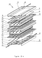
- the purification device 30 is a plane membrane device of the bimembrane type. This device 30 has in fact a single inlet 11 for the liquid to be treated, a single outlet 12 for the liquid concentrated in cellular elements, but two outlets 8 for the purified liquid.
- This device consists of two units for purifying the liquid to be treated, each comprising a filtration membrane 2, an intermediate plate 17 as well as a microporous structure 3 constituted by a stack of microporous membranes treated for the biospecific purification of the filtered liquid.
- the two purification units are arranged symmetrically with respect to a median frame 28 separating the two filtration membranes 2.
- This median frame 28 is provided with a gadroon 106 intended to seal with the peripheral edges of the median frames 17.
- the liquid to be treated is introduced into the purification device through an inlet 11 located on the middle frame at one end of the device. It then flows between the two membranes where it is filtered. The liquid concentrated in cellular elements is collected at the opposite end of the device and is discharged through an outlet 12 located on the middle frame 28.
- the filtration and purification of the liquid to be treated is thus carried out symmetrically in each of the purification units.
- the purification device 30 makes it possible, in a very compact form, to significantly increase the filtration and purification capacities of the device 20 shown in Figure II.
- the middle frame 28 of the purification device 30 is deleted; the inlet 11 of the liquid to be treated and the outlet 12 of the liquid concentrated in cellular elements are constituted by two end pieces housed between the intermediate plates 17 of the two purification units thanks to recesses 29 provided for this purpose. Sealing is ensured at the level of the membranes 2 for separating the cellular elements from the liquid to be treated by filling the grooves 107 of the intermediate plates 17.
- the device 30 further comprises on each of the intermediate plates 17 pressure taps 31 of the plasma to be purified.
- the purification device 40 is also a device with flat membranes of the bimembrane type.
- This device 40 consists of two purification units in the same way as the device 30, but in this case two inlets 11 of the liquid to be treated, two outlets 12 of the liquid enriched in cellular elements, a single outlet 8 of the purified liquid.
- the two purification units each comprise an external plate 5 of the same type as the upper plate 5 of the device 1 shown in FIG. I and comprising two lateral pipes 9 and 10 respectively for entering and leaving the liquid.
- Each purification unit also comprises a membrane 2 for separating the cellular elements by tangential filtration, an intermediate plate 17, a microporous structure 3 constituted by a stack of microporous membranes treated for the biospecific purification of the liquid to be treated.
- the structure of the device 40 is such that the various elements constituting each of the purification units are assembled symmetrically with respect to a central plate 32 separating the two stacks of membranes treated for biospecific purification.
- This central plate has on each of its faces longitudinal grooves forming a useful area for the circulation of the purified liquid.
- the flows inside the device 40 are symbolized by the arrows shown in Figure Va.
- the liquid to be treated is introduced through each of the pipes 9 of the plates 5.
- the separation of the cellular elements from the liquid to be treated is carried out by tangential filtration along the filtration membranes 2.
- the liquid concentrated in cellular elements is collected in line 10 from which it is discharged outside the device.
- the liquid obtained by filtration along the membrane 2 flows over the useful area of one of the faces of the intermediate plate to pass the passage 18 before being distributed on the other face of the plate 17.
- This liquid purifying then crosses the microporous structure 3 formed by the stack of purification membranes.
- the purified liquid is then collected using the grooves located on each of the faces of the central plate 32. All of the purified liquid thus obtained is led outside the device 40 via the outlet 8.
- the liquid to be purified is blood
- plasma is obtained by tangential filtration along the plasma filtration membrane 2. This plasma is purified by transverse filtration through the purification membranes.
- the purified plasma collected using the grooves in the central plate is led to the outside via outlet 8; this purified plasma can then be recombined with the blood concentrated in cellular elements coming from the outlet line 10 before being, for example, returned to a patient from where the blood to be purified comes.
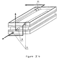
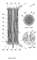
- the purification device 50 is a device of a mixed type comprising a membrane of the planar type, as well as hollow fibers.
- This purification device comprises, in a cylindrical envelope 33, a filtration membrane 34 constituted by an internal bundle of hollow fibers as well as a microporous plane membrane 35 treated for the biospecific purification of the liquid.
- the bundle of hollow fibers surrounds a central tube 36, and the purification membrane 35 is itself wound around the bundle 34.
- the central winding tube 36 can be made for example of polycarbonate, polyvinyl chloride or acrylonitrile -butadiene-styrene.
- the hollow fibers and the rolled up flat membrane are sealed at each end of the bundle using a potting resin common, in polyurethane for example.
- a potting resin common in polyurethane for example.
- an intermediate grid 37 can be provided between the hollow fiber bundle 34 and the purification membrane 35.
- This grid is for example constituted by a fabric having a thickness of approximately 100 to 110 microns of solid polyester.
- the fabric marketed by the company UGB under the mono reference TI 75-55775 is quite suitable.
- the winding of the membrane 35 is carried out continuously and uninterrupted.
- the purification device 50 comprises at each end of the cylindrical envelope 33 a cover (38, 39).
- the cover 38 is provided with a tube 41 intended for the entry of the liquid to be treated.
- the internal profile of this cover 38 is such that it defines an annular chamber 45 for distributing the liquid to be treated into which the tubing 41 opens.
- the axial part of the cover comes slightly insert inside the bundle of hollow fibers by means of a shoulder 47, while it is extended outside by a tube 43 which can be connected to means (not shown) for measuring the pressure of the filtered liquid to purify.
- This pressure tap is possible thanks to openings 108 in the central tube 36 which are placed in communication with the tubing 43 by means of a peripheral groove 109.
- the sealing of the distribution chamber 45 is ensured by two seals toric, 49 and 54 respectively.
- the cover 39 is provided with a tube 42 intended for the outlet of the liquid concentrated in cellular elements.
- the internal profile of this cover 39 makes it possible to define an annular chamber 46 for collecting the liquid concentrated in cellular elements on which the tubing 42 opens.
- the axial part 52 of the cover 39 is inserted slightly inside the bundle of hollow fibers thanks to a shoulder 48.
- the tightness of the collection chamber is ensured by two O-rings, respectively 51 and 53.
- the cylindrical envelope 33 also comprises a tube 44 allowing the evacuation of the purified liquid.
- the liquid to be treated containing cellular elements is introduced through the tubing 41 into the distribution zone 45 of the cover 38. It then penetrates inside the hollow fibers 34 which are open on the distribution zone 45
- the circulation of the liquid to be treated inside the hollow fibers makes it possible to separate, by tangential filtration, the cellular elements from the liquid to be treated.
- the liquid to be treated is blood
- one thus obtains a separation of the blood cells from the plasma which is then purified by transverse filtration through the microporous flat membrane 35 treated to ensure the biospecific purification of the liquid devoid of cellular elements. .
- the liquid concentrated in cellular elements is collected in the collection zone 46 of the cover 39 and is evacuated outside by the tubing 42.
- the purified liquid which in the case of blood treatment is purified plasma, is discharged outside the device through the tubing 44.
- This purified plasma may possibly be recombined, outside the purification device 50, with the blood concentrated in cellular elements originating from the tubing 42, in order to reconstitute whole but purified blood.
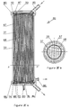
- the hollow fibers 34 for tangential filtration of the liquid to be treated are located on the periphery of the purification device 60, while the membrane 35 treated for biospecific purification is wound around the tube 36.
- the cover 55 is provided with a tube 57 for entering the liquid to be treated, but in this case, the distribution zone 62 of the liquid to be treated is located at the periphery of the cover 55.
- An O-ring 64 ensures the tightness of the distribution zone 62 at the level of the intermediate grid 37.
- the cover 56 is provided with a pipe 58 for the outlet of the liquid concentrated in cellular elements and in its axial part, with a pipe 59 for the outlet of the purified liquid as shown in detail in Figure VIIc.
- the purified dialysis liquid is collected in the pipe of the tubing 59 thanks to a peripheral groove 111 located on the part of the cover which is inserted inside the winding tube 36 and to openings 110 formed in the tube 36 at the level of the peripheral throat.
- the seal between the membrane 35 and the tubing 59 is provided by an O-ring 66.
- the collection zone 63 for the liquid concentrated in cellular elements is located at the periphery of the cover 56.
- the seal is provided by an O-ring 65.
- L 'cylindrical casing 33 also comprises a tube 61 allowing a pressure tap of the filtered liquid to be purified.
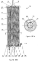
- the purification device 70 is a device made entirely of hollow fibers, in particular an internal bundle 67 of fibers for the tangential filtration of the liquid to be purified and a bundle external 68 of fibers treated for biospecific purification.
- the two beams are separated by an intermediate grid 37 and are arranged inside a cylindrical envelope 33.
- the device 70 comprises, in the same way as the devices 50 and 60, two covers 69 and 71.
- the cover 69 is provided with an axial tube 72 intended for the entry of the liquid to be treated.
- the profile of the cover 69 is such that a distribution zone 73 of the liquid to be treated communicates with the interior of the hollow fibers 67 located at the center of the device.
- An O-ring 74 seals the distribution zone 73 at the level of the intermediate grid 37.
- the cover 71 is provided with an axial tube 75 intended for the exit of the liquid concentrated in cellular elements, and on its periphery, with a tube 81 intended for the evacuation of the purified liquid.
- the internal profile of the cover 71 is such that it forms a central zone 76 for collecting the liquid enriched with cellular elements, into which the interior of the hollow fibers 67 of the internal bundle opens.
- an annular collection zone 78 of the purified liquid is formed by a peripheral groove drawn on the internal face of the cover 71. The sealing of this collection zone is ensured by two O-rings 77 and 79.
- the peripheral envelope 33 also includes a tubing 82 allowing a pressure tapping of the filtered liquid to be purified.
- the operation of the purification device 70 according to this embodiment is as follows. The liquid to be treated is introduced into the distribution zone 73 through the tubing 72, then enters the hollow fibers constituting the internal bundle 67.
- the circulation of the liquid inside these fibers 67 makes it possible to separate cellular elements of the liquid by tangential filtration along the fiber wall.
- the liquid enriched in cellular elements is collected in the zone 76 then evacuated outside by the tubing 75.
- the filtered fraction of the liquid to be treated crosses the intermediate grid 37 and penetrates inside the hollow fibers 68 by filtration through the microporous membrane constituting the wall of the hollow fibers 68.
- This membrane being treated to ensure the biospecific purification of a liquid, the liquid circulating inside these hollow fibers is a purified liquid which is collected in the annular zone 78 and is discharged outside through the tubing 81.
- the purification device 80 shown in Figures IXa and IXb is also a device made only of hollow fibers.
- the hollow fibers 67 for the separation of the cellular elements from the liquid to be purified by tangential filtration are located at the periphery of the device, while the hollow fibers 68 whose wall constitutes the microporous structure for biospecific purification, form the internal part of the beam.
- the two beams are separated by an intermediate grid 37
- the cover 83 is provided on its internal face with a peripheral groove constituting an annular zone 87 for distributing the liquid to be treated. This distribution area is sealed by two O-rings 92 and 93.
- the cover 84 is provided on its internal face with a peripheral groove constituting a zone 88 for collecting the liquid concentrated in cellular elements, into which opens a tube 86 for discharging this concentrated liquid.
- the tightness of this collection zone is ensured by two O-rings 94 and 95.
- the central part of the cover 84 also forms a collection zone 91 for the purified liquid, which is extended by an axial tube 89 for the outlet of this purified liquid. .
- FIGS Xa and Xb show another embodiment of a purification device 90 incorporating a membrane 101 for tangential filtration of the liquid to be purified arranged in a helix around a microporous membrane 102 for biospecific purification.
- This microporous membrane 102 is a flat membrane itself wound around a cylinder 103.
- These membranes are contained in a cylindrical envelope 104 having laterally a tubing 96 for inlet of the liquid to be treated, a tubing 97 for outlet of the liquid concentrated in cellular elements.
- the purification device 90 further comprises a tube 98 for the outlet of the purified liquid as well as a tube 99 allowing a pressure tapping of the filtered liquid to be purified.
- the purification device that is the subject of the present invention makes it possible to treat a liquid in a single housing successively by filtration. tangential then immediately by transverse filtration.
- the liquid treated may be blood, as has been described, but also any other liquid containing cellular elements, which it is desired to eliminate before ensuring the biospecific purification of the liquid.
- a cell suspension such as a suspension of transformed cells or bacteria
- purifying the liquid by transverse filtration through the microporous structure treated to ensure the biospecific purification of the liquid, in order to isolate, for example, monoclonal antibodies or proteins produced by bacteria.
Landscapes
- Health & Medical Sciences (AREA)
- Engineering & Computer Science (AREA)
- Heart & Thoracic Surgery (AREA)
- Biomedical Technology (AREA)
- Life Sciences & Earth Sciences (AREA)
- Public Health (AREA)
- Hematology (AREA)
- Anesthesiology (AREA)
- Animal Behavior & Ethology (AREA)
- General Health & Medical Sciences (AREA)
- Vascular Medicine (AREA)
- Veterinary Medicine (AREA)
- Chemical & Material Sciences (AREA)
- Chemical Kinetics & Catalysis (AREA)
- Water Supply & Treatment (AREA)
- Cell Biology (AREA)
- Molecular Biology (AREA)
- Biodiversity & Conservation Biology (AREA)
- Separation Using Semi-Permeable Membranes (AREA)
- External Artificial Organs (AREA)
- Detergent Compositions (AREA)
Priority Applications (1)
| Application Number | Priority Date | Filing Date | Title |
|---|---|---|---|
| AT89420088T ATE75621T1 (de) | 1988-03-25 | 1989-03-10 | Integrierte vorrichtung zur biospezifischen reinigung einer zellen enthaltenden fluessigkeit. |
Applications Claiming Priority (2)
| Application Number | Priority Date | Filing Date | Title |
|---|---|---|---|
| FR8804234 | 1988-03-25 | ||
| FR8804234A FR2628974A1 (fr) | 1988-03-25 | 1988-03-25 | Dispositif integre pour l'epuration biospecifique d'un liquide contenant des elements cellulaires |
Publications (2)
| Publication Number | Publication Date |
|---|---|
| EP0334774A1 true EP0334774A1 (de) | 1989-09-27 |
| EP0334774B1 EP0334774B1 (de) | 1992-05-06 |
Family
ID=9364816
Family Applications (1)
| Application Number | Title | Priority Date | Filing Date |
|---|---|---|---|
| EP89420088A Expired - Lifetime EP0334774B1 (de) | 1988-03-25 | 1989-03-10 | Integrierte Vorrichtung zur biospezifischen Reinigung einer Zellen enthaltenden Flüssigkeit |
Country Status (6)
| Country | Link |
|---|---|
| US (1) | US5015388A (de) |
| EP (1) | EP0334774B1 (de) |
| JP (1) | JP2921848B2 (de) |
| AT (1) | ATE75621T1 (de) |
| DE (1) | DE68901411D1 (de) |
| FR (1) | FR2628974A1 (de) |
Cited By (3)
| Publication number | Priority date | Publication date | Assignee | Title |
|---|---|---|---|---|
| EP0589572A1 (de) * | 1992-08-27 | 1994-03-30 | Pall Corporation | Behandlung von Proteinhaltigen Körperflüssigkeiten |
| EP1810742A1 (de) * | 2006-01-18 | 2007-07-25 | United Technologies Corporation | Brennstoffentgasungssystem mit nichtmetallischer Brennstoffplattenanordnung |
| ITPD20100001A1 (it) * | 2010-01-08 | 2011-07-09 | Federico Nalesso | Filtro per plasma separazione ed assorbimento combinate alimentato da singola pompa |
Families Citing this family (38)
| Publication number | Priority date | Publication date | Assignee | Title |
|---|---|---|---|---|
| US5232589A (en) * | 1987-10-02 | 1993-08-03 | Kopf Henry B | Filter element and support |
| US5176828A (en) * | 1991-02-04 | 1993-01-05 | Millipore Corporation | Manifold segment stack with intermediate feed manifold |
| US5139680A (en) * | 1991-06-05 | 1992-08-18 | Yuri Tarnopolsky | Method for continuous multicomponent separation using anisotropic separation bed |
| FR2678950B1 (fr) * | 1991-07-09 | 1993-11-05 | Bertin Et Cie | Cartouche, dispositif et procede d'extraction d'acides nucleiques tels que l'adn a partir d'un echantillon de sang ou de cellules de tissus. |
| US5183569A (en) * | 1991-12-16 | 1993-02-02 | Paradigm Biotechnologies Partnership | Filtration apparatus and process |
| US5308508A (en) * | 1992-05-15 | 1994-05-03 | Womack International, Inc. | High capacity filter media, method of use in filtration and method of formation |
| EP0605704A4 (de) * | 1992-06-29 | 1994-11-17 | Edward Shanbrom | Konservierung von blut, gewebe und biologischen flüssigkeiten durch stärke-iod-peroxid. |
| US7332125B2 (en) * | 1994-10-13 | 2008-02-19 | Haemonetics Corporation | System and method for processing blood |
| USD371439S (en) | 1994-11-15 | 1996-07-02 | Pall Corporation | Multiple compartment cassette |
| DE19510096A1 (de) * | 1995-03-20 | 1996-09-26 | Leybold Ag | Matrize zum Abformen von Schallaufzeichnungen und Verfahren zu ihrer Herstellung |
| US5868936A (en) * | 1996-06-20 | 1999-02-09 | Baxter International Inc. | Affinity membrane system and method of using same |
| US5942112A (en) * | 1997-10-17 | 1999-08-24 | Ishak; Noshi A. | Hollow fiber ultradialyzer apparatus |
| US6241945B1 (en) * | 1998-03-16 | 2001-06-05 | Life Science Holdings, Inc. | Modular combined pump, filtration, oxygenation and/or debubbler apparatus |
| AUPP576598A0 (en) * | 1998-09-07 | 1998-10-01 | Life Therapeutics Limited | Cassette for macromolecule purification |
| US6251291B1 (en) | 1998-12-28 | 2001-06-26 | Tranfusion Technologies Corporation | Reservoir-and-filter system and method of use |
| DE10000186C2 (de) * | 2000-01-05 | 2003-09-04 | Sartorius Gmbh | Vorrichtung und Anlage zur Crossflow-Filtration |
| AUPQ691400A0 (en) * | 2000-04-14 | 2000-05-11 | Life Therapeutics Limited | Separation of micromolecules |
| US20040228829A1 (en) * | 2003-03-11 | 2004-11-18 | Roberts Craig P. | Plasma detoxification system and methods of use |
| US8038638B2 (en) * | 2004-02-23 | 2011-10-18 | Hemolife Medical, Inc. | Plasma detoxification and volume control system and methods of use |
| EP1765433B1 (de) * | 2004-06-21 | 2016-05-18 | Hemolife Medical, Inc. | Plasmaentgiftung und volumensteuerungssystem |
| US8339447B2 (en) * | 2004-10-21 | 2012-12-25 | Truevision Systems, Inc. | Stereoscopic electronic microscope workstation |
| US8157103B2 (en) * | 2009-09-22 | 2012-04-17 | Haemonetics Corporation | Reservoir for use with a blood collection system |
| WO2013103906A1 (en) * | 2012-01-04 | 2013-07-11 | Medtronic, Inc. | Multi-staged filtration system for blood fluid removal |
| US8986238B2 (en) | 2012-08-15 | 2015-03-24 | Cyclone Medtech, Inc. | Systems and methods for salvaging red blood cells for autotransfusion |
| US10850016B2 (en) | 2013-02-01 | 2020-12-01 | Medtronic, Inc. | Modular fluid therapy system having jumpered flow paths and systems and methods for cleaning and disinfection |
| US10010663B2 (en) | 2013-02-01 | 2018-07-03 | Medtronic, Inc. | Fluid circuit for delivery of renal replacement therapies |
| US9623164B2 (en) | 2013-02-01 | 2017-04-18 | Medtronic, Inc. | Systems and methods for multifunctional volumetric fluid control |
| US9144640B2 (en) | 2013-02-02 | 2015-09-29 | Medtronic, Inc. | Sorbent cartridge configurations for improved dialysate regeneration |
| JP7004569B2 (ja) | 2014-10-07 | 2022-01-21 | ヘモネティクス・コーポレーション | 流出血液の洗浄システムおよび方法 |
| US10874787B2 (en) | 2014-12-10 | 2020-12-29 | Medtronic, Inc. | Degassing system for dialysis |
| US10098993B2 (en) | 2014-12-10 | 2018-10-16 | Medtronic, Inc. | Sensing and storage system for fluid balance |
| US9713665B2 (en) | 2014-12-10 | 2017-07-25 | Medtronic, Inc. | Degassing system for dialysis |
| EP3278865B1 (de) * | 2015-03-30 | 2019-06-19 | Mitsubishi Heavy Industries Engineering, Ltd. | Membranabscheidungsvorrichtung |
| WO2017223318A1 (en) | 2016-06-24 | 2017-12-28 | Dominique Uhlmann | System and Method for Continuous Flow Red Blood Cell Washing |
| US11278654B2 (en) | 2017-12-07 | 2022-03-22 | Medtronic, Inc. | Pneumatic manifold for a dialysis system |
| US11033667B2 (en) | 2018-02-02 | 2021-06-15 | Medtronic, Inc. | Sorbent manifold for a dialysis system |
| US11110215B2 (en) | 2018-02-23 | 2021-09-07 | Medtronic, Inc. | Degasser and vent manifolds for dialysis |
| US12128165B2 (en) | 2020-04-27 | 2024-10-29 | Mozarc Medical Us Llc | Dual stage degasser |
Citations (3)
| Publication number | Priority date | Publication date | Assignee | Title |
|---|---|---|---|---|
| US4013564A (en) * | 1975-03-17 | 1977-03-22 | Takeda Chemical Industries, Ltd. | Multipurpose metabolic assist system |
| DE2828549A1 (de) * | 1978-06-29 | 1980-01-17 | Fresenius Chem Pharm Ind | Apparat fuer blutbehandlung |
| GB2040724A (en) * | 1979-01-29 | 1980-09-03 | Baxter Travenol Lab | Plasma treatment apparatus |
Family Cites Families (14)
| Publication number | Priority date | Publication date | Assignee | Title |
|---|---|---|---|---|
| US3579441A (en) * | 1968-04-19 | 1971-05-18 | Hydronautics | Blood purification by dual filtration |
| SE320155B (de) * | 1969-03-21 | 1970-02-02 | V Hyden | |
| US3734851A (en) * | 1969-12-29 | 1973-05-22 | K Matsumura | Method and device for purifying blood |
| JPS5225197B2 (de) * | 1973-09-19 | 1977-07-06 | ||
| GB1558370A (en) * | 1975-09-26 | 1979-12-28 | Asahi Chemical Ind | Blood treating apparatus |
| JPS5340691A (en) * | 1976-04-01 | 1978-04-13 | Korufu Fuaundeeshiyon Za | Method and apparatus for removing impurities from fluids |
| DE2758679A1 (de) * | 1977-12-29 | 1979-07-05 | Fresenius Chem Pharm Ind | Apparat fuer blutbehandlung |
| JPH0218858B2 (de) * | 1979-06-11 | 1990-04-26 | Gambro Lundia Ab | |
| JPS6045359A (ja) * | 1983-08-19 | 1985-03-11 | 鐘淵化学工業株式会社 | 血液浄化器 |
| JPS62114606A (ja) * | 1985-11-12 | 1987-05-26 | Toyo Soda Mfg Co Ltd | 膜分離装置 |
| WO1988009693A1 (en) * | 1987-06-03 | 1988-12-15 | Eastman Kodak Company | Reverse osmosis apparatus |
| IT1215765B (it) * | 1988-01-22 | 1990-02-22 | Grace W R & Co | Dispositivo di emodiafiltrazione erelativo procedimento di emodiafiltrazione. |
| US4849102A (en) * | 1988-05-31 | 1989-07-18 | Filtron Technology Corporation | Bidirectional ultrafiltration apparatus |
| JP6046983B2 (ja) | 2012-11-05 | 2016-12-21 | アスモ株式会社 | 電動ポンプ |
-
1988
- 1988-03-25 FR FR8804234A patent/FR2628974A1/fr not_active Withdrawn
-
1989
- 1989-03-10 AT AT89420088T patent/ATE75621T1/de not_active IP Right Cessation
- 1989-03-10 DE DE8989420088T patent/DE68901411D1/de not_active Expired - Lifetime
- 1989-03-10 EP EP89420088A patent/EP0334774B1/de not_active Expired - Lifetime
- 1989-03-20 JP JP1066475A patent/JP2921848B2/ja not_active Expired - Fee Related
- 1989-03-24 US US07/327,621 patent/US5015388A/en not_active Expired - Lifetime
Patent Citations (3)
| Publication number | Priority date | Publication date | Assignee | Title |
|---|---|---|---|---|
| US4013564A (en) * | 1975-03-17 | 1977-03-22 | Takeda Chemical Industries, Ltd. | Multipurpose metabolic assist system |
| DE2828549A1 (de) * | 1978-06-29 | 1980-01-17 | Fresenius Chem Pharm Ind | Apparat fuer blutbehandlung |
| GB2040724A (en) * | 1979-01-29 | 1980-09-03 | Baxter Travenol Lab | Plasma treatment apparatus |
Cited By (4)
| Publication number | Priority date | Publication date | Assignee | Title |
|---|---|---|---|---|
| EP0589572A1 (de) * | 1992-08-27 | 1994-03-30 | Pall Corporation | Behandlung von Proteinhaltigen Körperflüssigkeiten |
| EP1810742A1 (de) * | 2006-01-18 | 2007-07-25 | United Technologies Corporation | Brennstoffentgasungssystem mit nichtmetallischer Brennstoffplattenanordnung |
| US7569099B2 (en) | 2006-01-18 | 2009-08-04 | United Technologies Corporation | Fuel deoxygenation system with non-metallic fuel plate assembly |
| ITPD20100001A1 (it) * | 2010-01-08 | 2011-07-09 | Federico Nalesso | Filtro per plasma separazione ed assorbimento combinate alimentato da singola pompa |
Also Published As
| Publication number | Publication date |
|---|---|
| US5015388A (en) | 1991-05-14 |
| FR2628974A1 (fr) | 1989-09-29 |
| JPH0211157A (ja) | 1990-01-16 |
| ATE75621T1 (de) | 1992-05-15 |
| JP2921848B2 (ja) | 1999-07-19 |
| DE68901411D1 (de) | 1992-06-11 |
| EP0334774B1 (de) | 1992-05-06 |
Similar Documents
| Publication | Publication Date | Title |
|---|---|---|
| EP0334774B1 (de) | Integrierte Vorrichtung zur biospezifischen Reinigung einer Zellen enthaltenden Flüssigkeit | |
| EP0822976B1 (de) | Bioreaktor | |
| FR2486812A1 (fr) | Appareil, constitue de plaques de support et de morceaux d'une membrane semi-permeable, pour la separation de fluides | |
| FR2490964A1 (fr) | Separateur de plasma | |
| CH627369A5 (fr) | Rein artificiel a fibres creuses et son procede de fabrication. | |
| EP0052571B1 (de) | Künstliche Niere mit integriertem Dialyseflüssigkeitskreis | |
| WO2007095771A1 (fr) | Chambre de centrifugation circulaire pour la separation du sang | |
| FR2597359A1 (fr) | Element filtrant plan a membrane formant une cellule lamellaire de filtration et filtre a pression a flux tangentiel comportant des empilements de tels elements. | |
| EP0686424A1 (de) | Anorganisches Mehrkanal-Filterelement zum Filtrieren von Fluiden | |
| FR2540992A1 (fr) | Dispositif pour verifier la sterilite de fluides et procede de fabrication de recipients de verification de la sterilite | |
| FR2631246A1 (fr) | Procede, dispositif et module de filtre en vue de la filtration de liquides en fonctionnement a ecoulement croise | |
| EP0448466A1 (de) | Verbesserungen an Membranfiltern für Ultra- oder Mikrofiltration von Flüssigkeiten, insbesondere von Wasser | |
| FR2653031A1 (de) | ||
| FR2799986A1 (fr) | Unite de filtration d'une substance virucide | |
| FR2647362A1 (fr) | Element filtrant tubulaire pour filtration avec debordement | |
| EP0120750B1 (de) | Vorrichtung zur tangentialen Filterung und diese Vorrichtung umfassende Anlage | |
| WO2002024256A1 (fr) | Dispositif de filtration a plusieurs milieux filtrants et systeme a poches le comprenant | |
| FR2649621A1 (fr) | Element de filtre a gaz | |
| EP2705132A1 (de) | Verfahren zur gewinnung von mikroalgen und vorrichtung zur durchführung dieses verfahrens | |
| FR2678950A1 (fr) | Cartouche, dispositif et procede d'extraction d'acides nucleiques tels que l'adn a partir d'un echantillon de sang ou de cellules de tissus. | |
| EP0014166A1 (de) | Medische Membranvorrichtung zum Austausch und/oder Trennen von Flüssigkeiten, deren Verwendung bei der Behandlung des Blutes und Blutbehandlungskreislauf mit einer solchen Vorrichtung | |
| CA1052284A (fr) | Appareil a membranes tubulaires sur supports pour le traitement de fluides | |
| FR2493707A1 (fr) | Appareil, utilisable comme rein artificiel, comportant des plaques a canaux decouverts | |
| FR2802115A1 (fr) | Installation de permeation | |
| FR2510412A1 (fr) | Appareil de filtration du sang et d'epuration simultanee de l'hemofiltrat |
Legal Events
| Date | Code | Title | Description |
|---|---|---|---|
| PUAI | Public reference made under article 153(3) epc to a published international application that has entered the european phase |
Free format text: ORIGINAL CODE: 0009012 |
|
| 17P | Request for examination filed |
Effective date: 19890725 |
|
| AK | Designated contracting states |
Kind code of ref document: A1 Designated state(s): AT BE CH DE ES FR GB IT LI LU NL SE |
|
| 17Q | First examination report despatched |
Effective date: 19910404 |
|
| GRAA | (expected) grant |
Free format text: ORIGINAL CODE: 0009210 |
|
| ITF | It: translation for a ep patent filed | ||
| AK | Designated contracting states |
Kind code of ref document: B1 Designated state(s): AT BE CH DE ES FR GB IT LI LU NL SE |
|
| PG25 | Lapsed in a contracting state [announced via postgrant information from national office to epo] |
Ref country code: SE Effective date: 19920506 Ref country code: NL Effective date: 19920506 Ref country code: ES Free format text: THE PATENT HAS BEEN ANNULLED BY A DECISION OF A NATIONAL AUTHORITY Effective date: 19920506 Ref country code: AT Effective date: 19920506 |
|
| REF | Corresponds to: |
Ref document number: 75621 Country of ref document: AT Date of ref document: 19920515 Kind code of ref document: T |
|
| REF | Corresponds to: |
Ref document number: 68901411 Country of ref document: DE Date of ref document: 19920611 |
|
| GBT | Gb: translation of ep patent filed (gb section 77(6)(a)/1977) | ||
| NLV1 | Nl: lapsed or annulled due to failure to fulfill the requirements of art. 29p and 29m of the patents act | ||
| PLBE | No opposition filed within time limit |
Free format text: ORIGINAL CODE: 0009261 |
|
| STAA | Information on the status of an ep patent application or granted ep patent |
Free format text: STATUS: NO OPPOSITION FILED WITHIN TIME LIMIT |
|
| PG25 | Lapsed in a contracting state [announced via postgrant information from national office to epo] |
Ref country code: LU Free format text: LAPSE BECAUSE OF NON-PAYMENT OF DUE FEES Effective date: 19930331 |
|
| 26N | No opposition filed | ||
| PGFP | Annual fee paid to national office [announced via postgrant information from national office to epo] |
Ref country code: BE Payment date: 20000228 Year of fee payment: 12 |
|
| PGFP | Annual fee paid to national office [announced via postgrant information from national office to epo] |
Ref country code: CH Payment date: 20000608 Year of fee payment: 12 |
|
| PG25 | Lapsed in a contracting state [announced via postgrant information from national office to epo] |
Ref country code: LI Free format text: LAPSE BECAUSE OF NON-PAYMENT OF DUE FEES Effective date: 20010331 Ref country code: CH Free format text: LAPSE BECAUSE OF NON-PAYMENT OF DUE FEES Effective date: 20010331 Ref country code: BE Free format text: LAPSE BECAUSE OF NON-PAYMENT OF DUE FEES Effective date: 20010331 |
|
| BERE | Be: lapsed |
Owner name: HOSPAL INDUSTRIE Effective date: 20010331 |
|
| REG | Reference to a national code |
Ref country code: CH Ref legal event code: PL |
|
| REG | Reference to a national code |
Ref country code: GB Ref legal event code: IF02 |
|
| PGFP | Annual fee paid to national office [announced via postgrant information from national office to epo] |
Ref country code: GB Payment date: 20040205 Year of fee payment: 16 |
|
| PGFP | Annual fee paid to national office [announced via postgrant information from national office to epo] |
Ref country code: FR Payment date: 20040302 Year of fee payment: 16 |
|
| PGFP | Annual fee paid to national office [announced via postgrant information from national office to epo] |
Ref country code: DE Payment date: 20040331 Year of fee payment: 16 |
|
| PG25 | Lapsed in a contracting state [announced via postgrant information from national office to epo] |
Ref country code: IT Free format text: LAPSE BECAUSE OF NON-PAYMENT OF DUE FEES;WARNING: LAPSES OF ITALIAN PATENTS WITH EFFECTIVE DATE BEFORE 2007 MAY HAVE OCCURRED AT ANY TIME BEFORE 2007. THE CORRECT EFFECTIVE DATE MAY BE DIFFERENT FROM THE ONE RECORDED. Effective date: 20050310 Ref country code: GB Free format text: LAPSE BECAUSE OF NON-PAYMENT OF DUE FEES Effective date: 20050310 |
|
| PG25 | Lapsed in a contracting state [announced via postgrant information from national office to epo] |
Ref country code: DE Free format text: LAPSE BECAUSE OF NON-PAYMENT OF DUE FEES Effective date: 20051001 |
|
| GBPC | Gb: european patent ceased through non-payment of renewal fee |
Effective date: 20050310 |
|
| PG25 | Lapsed in a contracting state [announced via postgrant information from national office to epo] |
Ref country code: FR Free format text: LAPSE BECAUSE OF NON-PAYMENT OF DUE FEES Effective date: 20051130 |
|
| REG | Reference to a national code |
Ref country code: FR Ref legal event code: ST Effective date: 20051130 |