EP0333891B1 - Vorrichtung zum Fördern von Kleidungsstücken auf Bügeln - Google Patents
Vorrichtung zum Fördern von Kleidungsstücken auf Bügeln Download PDFInfo
- Publication number
- EP0333891B1 EP0333891B1 EP88104467A EP88104467A EP0333891B1 EP 0333891 B1 EP0333891 B1 EP 0333891B1 EP 88104467 A EP88104467 A EP 88104467A EP 88104467 A EP88104467 A EP 88104467A EP 0333891 B1 EP0333891 B1 EP 0333891B1
- Authority
- EP
- European Patent Office
- Prior art keywords
- clamp
- horizontal
- fixed
- movable
- respect
- Prior art date
- Legal status (The legal status is an assumption and is not a legal conclusion. Google has not performed a legal analysis and makes no representation as to the accuracy of the status listed.)
- Expired - Lifetime
Links
Images


Classifications
-
- B—PERFORMING OPERATIONS; TRANSPORTING
- B65—CONVEYING; PACKING; STORING; HANDLING THIN OR FILAMENTARY MATERIAL
- B65G—TRANSPORT OR STORAGE DEVICES, e.g. CONVEYORS FOR LOADING OR TIPPING, SHOP CONVEYOR SYSTEMS OR PNEUMATIC TUBE CONVEYORS
- B65G1/00—Storing articles, individually or in orderly arrangement, in warehouses or magazines
- B65G1/02—Storage devices
- B65G1/04—Storage devices mechanical
- B65G1/0457—Storage devices mechanical with suspended load carriers
-
- B—PERFORMING OPERATIONS; TRANSPORTING
- B65—CONVEYING; PACKING; STORING; HANDLING THIN OR FILAMENTARY MATERIAL
- B65G—TRANSPORT OR STORAGE DEVICES, e.g. CONVEYORS FOR LOADING OR TIPPING, SHOP CONVEYOR SYSTEMS OR PNEUMATIC TUBE CONVEYORS
- B65G2201/00—Indexing codes relating to handling devices, e.g. conveyors, characterised by the type of product or load being conveyed or handled
- B65G2201/02—Articles
- B65G2201/0229—Clothes, clothes hangers
Definitions
- the present invention relates to an assembly comprising a host computer for programmed controlled handling and transporting of objects, garments, clothes or the like as is defined in the first part of claim 1.
- a host computer for programmed controlled handling and transporting of objects, garments, clothes or the like as is defined in the first part of claim 1.
- Such an assembly is known from EP-A-0169156.
- the main object of this invention is the handling of clothes on hangers, and it is more specifically an apparatus able to move the clothes from one place to another, for example in a warehouse or workshop, following the instructions of a host computer.
- manipulators designed for other industries are not suited for handling clothes on hangers.
- the present invention is defined by the assembly according to claim 1.
- the apparatus includes a manipulator of two cartesian degrees of freedom, one horizontal and the other vertical, for having access to the hangers hanging on the bars which can be placed in a wide range of vertical and horizontal distances from it.
- a clamp is moved with the aforementioned degrees of freedom and collects the hangers, taking into account in the clamp conception a great variety of clothes and hanger forms.
- An autoguided vehicle as the physical support of the manipulator, provides the ability needed for the displacement in the horizontal plane.
- a dynamic support for hangers moved by an endless screw provides the storage for carrying more than one hanger at each time.
- the control of the necessary movements, according to the method of the invention is done by electronics devices.
- a system of communication with a host computer allows the exchange of information needed to manage the operations of an apparatus or a set of them.
- the assembly further has a manipulator apparatus comprising a system of vertical telescopic tubes with two external fixed tubes, another intermediate between them movable and guided longitudinally upon them, and another inner tube to the intermediate, movable and guided longitudinally upon it, the system of movement being formed by a a motor which can be controlled in position and which activates a system of transmission of movement such that it moves at the same time the inner tube with respect to the intermediate and the intermediate with respect to the two external tubes, and a horizontal profiled member fixed to the inner vertical tube above mentioned, another horizontal member movable and longitudinally guided over the fixed horizontal member and a movable clamp which is guided longitudinally over the movable horizontal member, the system of movement being formed by a motor which can be controlled in position and which activates a system of transmission of movement such that it moves at the same time the clamp with respect to the movable horizontal member and this one with respect to the horizontal fixed member until a certain distance established in both directions from an intermediate position, the clamp standing still with respect to the horizontal movable member while this is moving with
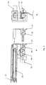
- Fig. 1 it can be seen the main parts of the apparatus generally designated as 1, the basic of which is the autoguided vehicle 2, which supports the dynamic support 3 for hangers and an extensible vertical arm 4 that supports another horizontal arm 5, upon which a clamp 6 can move.
- the autoguided vehicle 2 which supports the dynamic support 3 for hangers and an extensible vertical arm 4 that supports another horizontal arm 5, upon which a clamp 6 can move.
- the autoguided vehicle stands on three wheels 7 and 8, wheel 7 is in the front, and the two wheels 8 are in the back.
- the front wheel 7 applies the traction and driving function using two DC motors 9 and 10 with reducers, controlled in position by known electronic devices and the computer on board.
- the traction motor also acts as a brake when the security system is on.
- the back wheels 8 could also be stopped by the mechanism 11 when activated by the security system.
- the front wheel 7 stands on a metallic strip 12, of adequate magnetic properties, fixed to the floor of a warehouse or the like with adhesive tape.
- a sensor 13 placed before the front wheel, detects its relative position with respect to the magnetic strip 12 and gives the signals needed for activating the driving motor, allowing the alignment of the vehicle with the strip.
- Sensor 14 detects marks 15 on the floor, mainly bits of strip such as 12 of a specific length, which signal a curve or a side tracking at a distance from the mark, see Figure 9.
- Another sensor 16, Figure 1 similar to 14, detects other marks 17, similar to 15, placed in such a way that divides the circuit in sections of determined length.
- These sensors and marks can be used to calibrate the traction motor, to know the exact position of the vehicle on the circuit, and as a support for controlling the traffic, for example, preventing a vehicle to come in a section where there is another vehicle.
- a communications system between a host computer and the board computer allows the exchange of information between the two computers.
- the network system consists in a wireless transmitter-receiver, which establishes the exchange of information at any place and time within its range of action.
- the communications system, the board computer and the electronics for the control of motors are placed in a central module 18, in a location that does not interfere with the loading space for clothes.
- the batteries 19 are placed in a way that does not interfere with the loading area and also can be replaced quickly. The batteries can also have automatic loading.
- the aim of the security system is to detect external or internal incidences which affect or could affect the current working of the apparatus, to short circuit all the motors when a fail is detected, in order to activate the motors as brakes, to enable the brake of the back wheels, and also to tell about the fail to the host computer through the communications system.
- the motors are provided with encoders, so they can be controlled in position. This allows the activation of the security system when there is a lag of phase between the actual position and the ordered one.
- the dynamic support of hangers 3 affords the storage of a certain number of hangers. It is an endless screw 21 placed at the required height above the car and standing on it so it creates the entry and exit of hangers by the front part of the car.
- the endless screw is enabled by a DC motor 22 so it can rotate in one direction or the opposite following the instructions of the board computer.
- the hangers are then moved or brought by the endless screw from the loading/unloading mechanism 23 placed in the front of the screw (see Fig. 2), where the hangers are separated at a distance equal or higher than the pitch or step of the screw.
- This function is done by means of a helicoidal slot 24 having the same pitch as the endless screw whose depth is equal to the diameter of the hanger hook and a rigid fixed part 25 almost tangents to the endless screw. In this way, two hangers can not pass consecutively at a shorter distance than a step of the screw.
- the mechanism of loading/unloading consists in a screw 26 similar to 21, but its length is approximately a step, and in which the helicoidal slot 24 is lengthened.
- the screw 26 is guided in the inside of screw 21, so screw 26 can move straightly from 25, but they rotate together.
- the screw 26 is hinged to support 27 which by means of belt 28 can move in a straight line when activated by DC motor 29.
- the function of the mechanism for loading/unloading is to split the hanger ready for loading/unloading from the ones on the screw shaft, so that the hangers and the mechanism do not interfere with clamp 6 when moved.
- a sensor of hangers preferably a micro switch 30, detects the passing of a hanger from the mechanism of loading/unloading to the splitter of hangers and viceversa, and the signal is managed by the board computer in order to activate or deactivate motors 22 and 29 and the motor of arms 4 and 5.
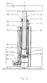
- the two tubes 31 are fixed parts of the extensible vertical arm 4 (see Fig. 3).
- Tube 32 slides over tubes 31, supported by guides 33, which are fixed on the top part of tubes 31, and on guides 34, fixed to the bottom of tube 32.
- the movement of tube 32 is done by means of motor 35 controlled in position, using a synchronous belt 36 fixed to tube 32.
- the inside tube 37 slides on tube 32 supported by guides 38, fixed to the top part of tube 32, and on guides 39, fixed to the bottom of tube 37.
- the movement of tube 37 is produced by a belt 40 which is fixed at one side to tube 37 and at the other to one of the fixed tubes 31, and is supported by two pulleys 41 fixed to tube 32. In this way tube 37 moves with respect to tube 32 when this one moves with respect to tubes 31, see Figure 3.
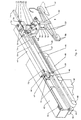
- a horizontal tube 43 fixed to the inner movable vertical tube 37 supports the movable horizontal tube 44 by way of different guides and supports, following the relative position between them (see Fig. 1 and 4).
- Guides 45 are fixed to tube 43 on both sides on top and bottom parts, such as guides 46 are fixed to tube 44.
- These guides equilibrate the horizontal loads and torques around the vertical and horizontal longitudinal axis on the horizontal tubes.
- the vertical loads and moments around the horizontal axis, longitudinal of the car, are equilibrated by means of rollers 47 fixed to both ends of tube 44 and pulleys 48 fixed to both ends of tube 43.
- a synchronous belt 49, externally and internally toothed, is mounted between pulleys 48 and interlocks with the bottom part of tube 44, properly mechanized.
- One of the pulleys 48 is fixed to motor 50 controlled in position, guiding the movement and its control of tube 44 along the tube 43 in a wide range of positions in both directions.
- Two micro switches fixed to tube 43 in both ends detect if tube 44 overranges its maximum stroke by both sides and activate in consequence the security system.
- Clamp 6 consists of a mechanism of articulated bars activated by a DC motor 51, mounted on a U-shaped frame 106 of the clamp.
- the motor enables a screwed axis 52 to rotate with respect to a screwed piece 53 that, unabled to rotate by the biforcated bars 54, moves over the length of the screwed axis.
- the motor is turned on by the on board computer when the operation sequence requires it, and turned off also by the computer when the piece 53 arrives to the other end of its stroke.
- the arriving signal can be given by a micro switch, see Figure 4.
- clamp pieces 58 includes a high number of retractable pins 60 (see Fig. 5) uniformly distributed over the fastening surface 59.
- the pins are pushed by a piece 61 made out of a material of high deformability and elasticity to compression like foams. In this way the pins adapt to the external shape of the hanger 62 and withstand the hanger weight not by friction, but by bending and shear.
- Other pins 63 placed front to front and centered on every clamp piece 58 allow the flow of an electric current when they contact: in this way it can be known whenever a hanger is picked by the left or by the right.
- Fig. 6 shows three singular posisitions of the clamping operation.
- Position A is that of the maximum clamping opening, and corresponds to the top positionn of piece 53.
- Position B is that of contact between clamp pieces 58 and hanger 62 and corresponds to an intermediate and variably position of piece 53, according to the width c of the hanger.
- Position C is that of clamping, and corresponds to the lower position of piece 53, when bars 54 form an angle of 180 degrees. In this position the maximum clamping pressure is reached for a determined maximum torque given by the motor 51.
- the torque stiffness of bars 55 and bending stiffness of arms 57 are related between them and with the possible hanger width c in order to reach the position C with a minimum clamping pressure and a given maximum motor torque.
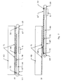
- the clamp 6 can slide along axis 64, which is fixed to the movable horizontal tube 44 (see Fig. 4) by way of the two linear bearings 65 of low coefficient of friction, placed on the top part of the frame 106 of the clamp.
- the equilibrium of the clamp is completed supporting its bottom part on guide 66, that is also fixed to the horizontal movable tube.
- Two cables 67 of the same length join the clamp to a piece 68 surrounding the horizontal movable tube by pulleys 69.
- Piece 68 can slide along guide 70, fixed to the movable horizontal tube 44, when it is placed in the proper lap which has in its central part the guide 71, which is fixed to the horizontal fixed tube 43, or it can slide along guide 71 when it is placed in one of the two fitted slots which has in its extremes the guide 70.
- piece 68 is placed on guide 71; see Figure 7A.
- the clamp moves with respect to the movable tube 44 such that this moves with respect to 43 and in the same direction. So then, when piece 68 is placed on guide 71, the displacements, velocities and accelerations of the clamp are twice those of the horizontal movable tube.
- Two tracers 74 hinged to the frame of the clamp 6 detect the actual position of the hanging bars with respect to the clamp, whether such bar is to the left or to the right of the apparatus.
- the tracer consists in a hinged bar (see Figs. 4 and 8) whose lower part includes, near the hinge 76, a zone 75 which is horizontal while the tracer is in normal position, and other zone 77, through the free end, which is slightly inclined while the tracer is in normal position.
- the micro switch 79 is placed in such a way that can be activated by either of the tracers.
- the way of detection of the actual relative position between a bar 80 and the clamp is as follows: Y and Z being the theoretical horizontal and vertical distances (previously measured) from the bar to the metallic band that guides the apparatures, the first operation would be placing the clamp, by means of extensible horizontal and vertical arms, in such a way that the mean point of zone 77 (whose length is a) is at a horizontal distance Y from the vertical axis of the apparatus and at a vertical distance Z + b from the floor.
- Y and Z being the theoretical horizontal and vertical distances (previously measured) from the bar to the metallic band that guides the apparatures
- the second operation would be a vertical movement, AB, until the micro switch 79 is activated, after the bar 80 has come in contact with zone 77.
- the third operation would be a horizontal movement, BC, until the micro switch 79 is deactivated, after the zone 77 leaves the top line of bar 80. In that moment the actual relative position between the bar and clamp is known, and the following movement, sequence CD, will lie in that a hanger is picked or released, on the left or on the right.
- the dimensions and relative positions between the left and right tracer and the pieces 58 are deduced from the dimensions of the hanging bar cross section and the hanger hook, taking into account the possibility of picking and releasing passing the hanger hook under and above the bars.
- Fig. 9 which shows a warehouse of this kind, can be seen the disposition of the bars 80, the magnetic tapes 12 which guide the vehicle, the marks 15 which signal a curve or a side-track, and the marks 17 which signal a determined position.
- There is an entry area where the garments come from the exterior and are picked by the apparatus in a known order.
- the bars are mechanized in a way that its top surface has toothed form, for avoiding swinging of the hangers with respect to their vertical axis when they are hanging. This function could be executed preferably by plastic pieces 83 which are clamped upon the bars (see Fig. 10).
- a host computer knows the placing of the magnetic tape 12 in the warehouse, and also the vertical and horizontal distance of the bars with respect to the magnetic tapes as stored in its memory.
- the hangers can arrive to the entry area using an endless screw, with the proper mechanisms needed for the apparatus to collect the clothes always in the same position.
- the apparatus 1 In a disposition like that of Fig. 9 the apparatus 1 will be placed in such a way that the hangers will be placed towards the axis + Y.
- the following movements will be executed (see Fig. 11).
- Movement from position 0 to A the clamp moves vertically in such a way that the tracer 74 is higher than the endless screw 84 which moves the clothes into the entry area.
- Movement from position I to H the clamp does the inverse movement to the afore mentioned activating then the mechanism for loading/unloading and the endless screw 21.
- Micro switch 30 detects the passing of the hanger and gives the signal for stopping the endless screw.
- Movement from position H to O the clamp returns to the initial position, or from position H to A, and the cycle is repeated for picking another hanger.
- the apparatus gets them into the warehouse and stores them in a prefixed order commanded by the host computer.
- the apparatus reaches each store position following marks 15 which indicate the correct path, marks 17 indicate determined positions that can be taken as new origins, and the traction motor controlled in position.
- the operations are similar, but in an approximately inverse sequence to those described above. If the bar is placed towards - Y axis, the operations for picking from the bar or hanging upon the bar are also similar to those described avove except that the hanger must go under the bar.
- the apparatus and the handling method described before could also be applied in a garment workshop. This would require an adequate design of the clamping elements for the clothes and its components that eased the handling of them in the workstations depending upon the different operations and that were compatible with the method and the apparatus described here.
- This application will be valuable to use as a dynamic support of the hangers, instead of the endless screw system described before, another system which can allow the direct access to any of the hangers on board of the apparatus, such as a chain in a closed loop where hang the clamping units for garments and components.
Landscapes
- Engineering & Computer Science (AREA)
- Mechanical Engineering (AREA)
- Warehouses Or Storage Devices (AREA)
- Intermediate Stations On Conveyors (AREA)
- Holders For Apparel And Elements Relating To Apparel (AREA)
- Chain Conveyers (AREA)
- Sewing Machines And Sewing (AREA)
- Vending Machines For Individual Products (AREA)
- Specific Conveyance Elements (AREA)
- Control Of Position, Course, Altitude, Or Attitude Of Moving Bodies (AREA)
- Manipulator (AREA)
- Control And Safety Of Cranes (AREA)
Claims (9)
- Anlage für den selbsttätigen Transport und die selbsttätige Handhabung von Gegenständen unter Verwendung eines Hostrechners und eines selbstgelenkten Fahrzeuges mit einem Manipulator für die selbsttätige Übergabe der Gegenstände aus einer Lagerstation an einen auf dem Fahrzeug befindlichen Zwischenspeicher bzw. von dem Zwischenspeicher an eine Lagerstation, wobei dem Fahrzeug Sensoren zugeordnet sind zur selbsttätigen Ermittlung von Verschiebepositionen zwischen Fahrzeug, Manipulator und Lagerstationen in einer Fabrik, einem Warenhaus oder ähnl., dadurch gekennzeichnet, daß der Zwischenspeicher für den Transport und die Handhabung von Kleidungsstücken (62) auf Bügeln eine über einen Motor (22) antreibbare horizontale Schnecke (21) und eine motorgetriebene der Schnecke vorgeschaltete und auf die Bewegungen des Manipulators (4,5,6) abgestimmte Be- und Entladeeinrichtung (23) umfaßt, daß der Manipulator über einen Motor (35) angetriebene senkrechte Teleskoprohre (31,32,27) und horizontale Profilteile (43,44) aufweist, von denen das eine Profilteil (43) an einem innenliegenden senkrechten Rohrstück (37) festigt ist und als Führung des anderen in Längsrichtung bewegbaren Profilteiles (44) dient, daß eine in Längsrichtung geführte bewegliche Klemmeinrichtung (6) vorgesehen ist, daß ein Motor (50) das Profilteil (44) und die Klemmvorrichtung (6) in Längsrichtung antreibt, daß die Klemmeinrichtung (51) und zwei Profilteilsensoren (74) aufweist, die an einander gegenüberliegenden Seiten der Klemmeinrichtung überstehen und mit den die Kleidungsstücke aufnehmenden Schienen zusammenwirken zwecks endgültiger Festlegung der Übergabestellung der Klemmeinrichtung (6) in bezug auf die Kleidungsstücke einer Lagerstation (80) und daß die Motoren (22,29,35, 50,51) für den Antrieb des Manipulators und der Schnecke (21) sowie der Be- und Entladevorrichtung (23) über einen weiteren Rechner (18) steuerbar sind, der im selbstgelenkten Fahrzeug angeordet ist.
- Anlage nach Anspruch 1 , dadurch gekennzeichnet, daß die beweglichen und ortsfesten Profilteile (43,44) Gleitführungen (45,46) zur gegenseitigen Führug aufweisen, daß die Klemmvorrichtung (6) über ein das horizontal bewegliche Profilteil (44) umschließendes biegsames Organ (67) geführt ist, daß das biegsame Organ (67) ein einen Anschlag für die Klemmvorrichtung (6) bildendes Teil (68) zur exaktion Positionierung in bezug auf die beweglichen und festen Profilteile (44,43) aufweist, daß dieser Anschlag (68) in Längsrichtung verschieblich und auf dem horizontal Profilteil (44) geführt ist, wenn dieser auf dem horizontalen Profilteil (43) eine vorbestimmte Stellung einnimmt und entlang dem festen Profilteil (43) in einer anderen vorbestimmten Stellung gleitet, daß diese Bewegungen automatisch durch Versetzen dieses Profilteils von einem Rohrstück zum anderen erfolgen, sobald es auf dem festen horizontalen Rohrstück fluchtrecht zu einer der beiden Stellungen im horizontal beweglichen Profilteil steht, daß die Bewegungen über einen lagegesteuerten Motor (50) erfolgen, der die antriebsübertragenden Mittel derart ansteuert, daß die Klemmvorrichtung (6) gleichzeitig in bezug auf das bewegliche horizontale Profilteil (44) und dieses in bezug auf das feststehende Bewegungen über einen lagegesteuerten Motor (50) erfolgen, der die antriebsübertragenden Mittel derart ansteuert, daß die Klemmvorrichtung (6) gleichzeitig in bezug auf das bewegliche horizontale Profilteil (44) und dieses in bezug auf das feststehende Profilteil bewegt werden, bis sie einen vorgegebenen Abstand in der einen oder anderen Richtung in bezug auf die Mittelstellung erreichen, bei dem die Klemmvorrichtung in bezug auf das horizontal bewegliche Profilteil fixiert ist, während das bewegliche Profilteil in bezug auf das feststehende Profilteil bewegbar ist, bis der vorgegebene Abstand erreicht ist.
- Anlage nach Anspruch 1, dadurch gekennzeichnet, daß die Anordnung von senkrechten Teleskoprohren (4) drei konzentrische Rohrstücke (31,32) umfaßt, von denen zwei nach außen feste Rohrstücke (31) sind, während ein Rohrstück (32) zwischen diesen in Längsrichtung beweglich ist und ein innenliegendes Rohr (37) umschließt, das die horizontalen Profilteile (43) trägt, und daß ein lagergeteuerter Motor (35) für die Ansteuerung des Übertragungssystems vorgesehen ist, durch den das innere Rohrstück gleichzeitig in bezug auf das mittlere und das mittlere Rohrstück in bezug auf die beiden äußeren Rohrstücke bewegbar sind.
- Anlage nach den Ansprüchen 1 bis 3, dadurch gekennzeichnet, daß die Klemmvorrichtung (6) des Manipulators (4) zwei einander gegenüberliegende horizontale Arme (57) aufweist, die parallel zu den horizontalen Profilteilen (43) angeordnet sind und an ihren freien Enden Befestigungsmittel (58) aus starren ebenen Klemmstücken (58) aufweisen, an denen biegesteife und abriebfeste sowie elastisch auf Druck reagierende Mittel insbesondere in Form von Stiften (60) vorgesehen sind, die sich auf einem nachgiebigen Werkstoff, wie Schaumstoff (61) abstützen und über die Dicke der starren und glatten Teile geführt sind und bei denen die horizontalen Arme (57) jeweils mittig mit der Klemmvorrichtung verbunden sind, derart, daß beim Klemmvorgang die beiden äußeren Enden der horizontalen Arme gleichzeitig gegeneinander bewegt werden.
- Anlage nach Anspruch 4, dadurch gekennzeichnet, daß die Klemmvorrichtung zwei einander gegenüberliegende Arme (54) aufweist, deren innenliegende Enden an einem Gewindeteil (53) angelenkt sind, das auf einer Spindel (52) längsverschieblich angeordnet ist und bei deren Verdrehung mitgenommen wird, daß die anderen Enden jeweils mit zwei senkrechten Armen (55) verbunden sind, die ihrerseits mit ihren nach unten weisenden Enden mit den horizontalen Armen (57) verbunden sind, daß die Arme (55) auf einer waagerechten Achse (56) gelagert sind und sich beim Drehen der Spindel (53) verschwenken, deren Steife in einem bestimmten Verhältnis zur Biegesteifigkeit der Hebel zwischen der Auflage und dem unteren Ende und zur Biegesteifigkeit der horizontalen Stäbe gewählt ist, um einen möglichst geringen Anpreßdruck für unterschiedliche Bügelbreiten und für eine vorgegebene Bewegung des Gewindeteils zu erzielen, und daß ein die Spindel (52) in der einen oder anderen Richtung in Abhängigkeit der jeweiligen Endlage des Gewindeteils antreibender Motor (51) vorgesehen ist, durch den das Gewindeteil (53) in die jeweils andere Endlage bewegbar ist, wobei die jeweilige Stellung des Gewindeteils in seinen Endlagen, vorzugsweise durch Mikroschalter abtastbar ist.
- Anlage nach Anspruch 4, dadurch gekennzeichnet, daß die beiden Sensoren an jeder Seite des Rahmens (106) der Klemmvorrichtung (6) parallel zu den horizontalen Profilteilen (43,44) angeordnete Aufnehmer (74) sind, die bei ihrem Absenken die jeweilige vertikale Stellung einer horizontal angeordneten Stange (80) abtasten und anschließend in einer horizontalen Bewegung die jeweilige horizontale Stllung der Stange (80) mit vorbestimmter Genauigkeit ermitteln.
- Anlage nach Anspruch 1, dadurch gekennzeichnet, daß die bewegliche Lagerstelle (Schnecke 21) für die auf Bügeln hängenden Kleidungsstücke derart ausgebildet ist, daß diese jeweils einzeln bei Freigabe durch die Klemmvorrichtung (6) aufnehmbar bzw. die zwischengelagerten Kleidungsstücke nacheinander oder mit willkürlichem Zugriff derart abnehmbar sind, daß diese von der Klemmvorrichtung (6) ergreifbar sind.
- Anlage nach Anspruch 7, dadurch gekennzeichnet, daß die Lade- und Entladevorrichtung (23) zwischen zwei Positionen beweglich ist, von denen eine die Aufnahmestellung (Position B) ist für die Aufnahme eines Bügels (62) von der Klemmvorrichtung (6) oder zur Übernahme eines Bügels durch die Klemmvorrichtung (6), und von denen die andere eine Abgabestellung (Position A) ist, in der ein Bügel von der Schnecke (21) der Vorrichtung abgenommen oder dieser zugeführt wird, wobei die Verrichtung in dieser Stellung außerhalb des Wirkungsbereiches der Klemmvorrichtung liegt und deren ungehinderte Bewegung erlaubt.
- Anlage nach Anspruch 7, dadurch gekennzeichnet, daß auf den Stangen (80) ein Hin- und Herbewegen der Bügel (62) um eine senkrechte Achse der Anlage verhindernde Zahnstangen (83) angeordnet sind.
Priority Applications (10)
| Application Number | Priority Date | Filing Date | Title |
|---|---|---|---|
| AT88104467T ATE67147T1 (de) | 1988-03-21 | 1988-03-21 | Vorrichtung zum foerdern von kleidungsstuecken auf buegeln. |
| DE8888104467T DE3864815D1 (de) | 1988-03-21 | 1988-03-21 | Vorrichtung zum foerdern von kleidungsstuecken auf buegeln. |
| EP88104467A EP0333891B1 (de) | 1988-03-21 | 1988-03-21 | Vorrichtung zum Fördern von Kleidungsstücken auf Bügeln |
| ES198888104467T ES2012744T3 (es) | 1988-03-21 | 1988-03-21 | Conjunto para la manipulacion de prendas en perchas. |
| DK246288A DK168661B1 (da) | 1988-03-21 | 1988-05-06 | Aggregat til håndtering af tøj på bøjler |
| FI882834A FI93093C (fi) | 1988-03-21 | 1988-06-14 | Laite ripustimilla olevien vaatteiden käsittelemiseksi |
| IE180688A IE61073B1 (en) | 1988-03-21 | 1988-06-15 | Method and apparatus for handling clothes on hangers |
| CA000575861A CA1325050C (en) | 1988-03-21 | 1988-08-26 | Method and apparatus for handling clothes on hangers |
| JP1042893A JPH07108722B2 (ja) | 1988-03-21 | 1989-02-21 | プログラム制御による衣服の操作・移送装置 |
| US07/770,776 US5156513A (en) | 1988-03-21 | 1991-10-04 | Apparatus for handling clothes on hangers |
Applications Claiming Priority (1)
| Application Number | Priority Date | Filing Date | Title |
|---|---|---|---|
| EP88104467A EP0333891B1 (de) | 1988-03-21 | 1988-03-21 | Vorrichtung zum Fördern von Kleidungsstücken auf Bügeln |
Publications (2)
| Publication Number | Publication Date |
|---|---|
| EP0333891A1 EP0333891A1 (de) | 1989-09-27 |
| EP0333891B1 true EP0333891B1 (de) | 1991-09-11 |
Family
ID=8198827
Family Applications (1)
| Application Number | Title | Priority Date | Filing Date |
|---|---|---|---|
| EP88104467A Expired - Lifetime EP0333891B1 (de) | 1988-03-21 | 1988-03-21 | Vorrichtung zum Fördern von Kleidungsstücken auf Bügeln |
Country Status (10)
| Country | Link |
|---|---|
| US (1) | US5156513A (de) |
| EP (1) | EP0333891B1 (de) |
| JP (1) | JPH07108722B2 (de) |
| AT (1) | ATE67147T1 (de) |
| CA (1) | CA1325050C (de) |
| DE (1) | DE3864815D1 (de) |
| DK (1) | DK168661B1 (de) |
| ES (1) | ES2012744T3 (de) |
| FI (1) | FI93093C (de) |
| IE (1) | IE61073B1 (de) |
Cited By (3)
| Publication number | Priority date | Publication date | Assignee | Title |
|---|---|---|---|---|
| US8060389B2 (en) | 2000-06-07 | 2011-11-15 | Apple Inc. | System and method for anonymous location based services |
| US8538685B2 (en) | 2000-06-07 | 2013-09-17 | Apple Inc. | System and method for internet connected service providing heterogeneous mobile systems with situational location relevant content |
| CN108529116A (zh) * | 2018-05-16 | 2018-09-14 | 卢俊超 | 一种可自动将药物送出的药物储存柜 |
Families Citing this family (22)
| Publication number | Priority date | Publication date | Assignee | Title |
|---|---|---|---|---|
| DE3864815D1 (de) * | 1988-03-21 | 1991-10-17 | Investronica Sa | Vorrichtung zum foerdern von kleidungsstuecken auf buegeln. |
| JPH0747403B2 (ja) * | 1990-05-22 | 1995-05-24 | インベストロニカ・ソシエダッド・アノニマ | プログラム制御による箱、コンテナ等の操作・移送装置 |
| US5344269A (en) * | 1991-10-29 | 1994-09-06 | Banks Edward J K | Automatic retrieval system |
| JPH05181527A (ja) * | 1991-12-27 | 1993-07-23 | Mitsubishi Electric Corp | 自動搬送装置 |
| US5550953A (en) * | 1994-04-20 | 1996-08-27 | The United States Of America As Represented By The Administrator Of The National Aeronautics And Space Administration | On-line method and apparatus for coordinated mobility and manipulation of mobile robots |
| US6558102B2 (en) * | 1997-08-29 | 2003-05-06 | psb GmbH Förderanlagen und Lagertechnik | High storage shelf system for hanging goods |
| JP3395061B2 (ja) | 2000-02-21 | 2003-04-07 | 学校法人金沢工業大学 | 図書館の蔵書自動出納システムと図書館の蔵書出納ロボットならびに図書館の蔵書出納ロボットのハンド機構 |
| US6571970B1 (en) * | 2000-10-16 | 2003-06-03 | Rapistan Systems Advertising Corp. | Monorail telescopic carrier |
| JPWO2004106009A1 (ja) | 2003-06-02 | 2006-07-20 | 松下電器産業株式会社 | 物品取扱いシステムおよび物品取扱いサーバ |
| CN100348374C (zh) * | 2004-12-02 | 2007-11-14 | 大连理工大学 | 一种移动式多手运输车 |
| DE102007013863B4 (de) * | 2007-03-20 | 2010-10-28 | Dematic Gmbh | Regallager für Hängeware und Verfahren zu dessen Betrieb |
| US20110231007A1 (en) * | 2010-03-19 | 2011-09-22 | Biehle Electric Inc. | Automated library |
| EP2692667A1 (de) | 2012-08-01 | 2014-02-05 | Dürkopp Fördertechnik GmbH | Regalbediengerät für ein Regallager, Regallager mit einem derartigen Regalbediengerät und Verfahren zum vereinzelten Entnehmen von Ware aus einem derartigen Regallager |
| US10026044B1 (en) | 2012-09-10 | 2018-07-17 | Amazon Technologies, Inc. | System and method for arranging an order |
| US9663293B2 (en) * | 2012-10-08 | 2017-05-30 | Amazon Technologies, Inc. | Replenishing a retail facility |
| US9758305B2 (en) | 2015-07-31 | 2017-09-12 | Locus Robotics Corp. | Robotic navigation utilizing semantic mapping |
| CN106697693A (zh) * | 2016-11-28 | 2017-05-24 | 宁夏向量信息技术有限公司 | 智能立体仓储装置 |
| CN110002162B (zh) * | 2019-04-27 | 2021-02-02 | 安徽凌坤智能科技有限公司 | 一种仓储复合机器人 |
| GB202008183D0 (en) | 2020-03-04 | 2020-07-15 | Ocado Innovation Ltd | Automated storage systems and devices |
| CA3132331A1 (en) * | 2020-09-29 | 2022-03-29 | Dianomix Inc. | Delivery vehicle with unloading arm |
| CN115676236A (zh) * | 2021-07-23 | 2023-02-03 | 青岛海尔智能技术研发有限公司 | Agv送衣小车 |
| SE2451102A1 (en) * | 2024-11-05 | 2025-11-04 | Jensen Sweden Ab | Garment hanger handling device securing arrangement |
Family Cites Families (28)
| Publication number | Priority date | Publication date | Assignee | Title |
|---|---|---|---|---|
| US3038970A (en) * | 1958-10-17 | 1962-06-12 | Gen Mills Inc | Vehicle guidance system |
| US3272347A (en) * | 1963-01-14 | 1966-09-13 | Jerome H Lemelson | Article manipulation apparatus |
| US3415385A (en) * | 1966-06-27 | 1968-12-10 | Rosse Fox Company | Automatic garment handling machine |
| US3464588A (en) * | 1967-11-02 | 1969-09-02 | Mc Graw Edison Co | Clothes hanger dispenser |
| US3495677A (en) * | 1968-01-31 | 1970-02-17 | American Chain & Cable Co | Guidance system |
| US3589535A (en) * | 1969-08-26 | 1971-06-29 | Simon Handling Eng Ltd | Transporting and stacking means with a correlated position sensing and load sensing means |
| US3549025A (en) * | 1969-10-09 | 1970-12-22 | Clark Equipment Co | Side loader device |
| US3561620A (en) * | 1969-12-15 | 1971-02-09 | Wilfred Ernest Willis | Side-loading attachment for fork-lift trucks |
| US4307988A (en) * | 1971-12-28 | 1981-12-29 | Page Peter H | Storage system |
| US3770148A (en) * | 1972-02-18 | 1973-11-06 | Mc Graw Edison Co | Screw conveyor system for durable press apparatus |
| SU636153A1 (ru) * | 1972-04-03 | 1978-12-05 | Проектно-Конструкторско-Технологический Институт Министерства Бытового Обслуживания Населения Украинской Сср | Подвесной толкающий конвейер с автоматическим адресованием |
| US3854616A (en) * | 1972-09-20 | 1974-12-17 | W Willis | Side-loading attachment for forklift trucks |
| US3814026A (en) * | 1973-02-02 | 1974-06-04 | Allis Chalmers | Stabilizing apparatus for lift trucks |
| DE2711349A1 (de) * | 1977-03-16 | 1978-09-28 | Ves Transporttechnik Gmbh & Co | Flurfahrendes lagerhausfahrzeug |
| EP0005539B1 (de) * | 1978-05-22 | 1981-12-09 | J. Sandt AG | Fördereinrichtung für mit einem Aufhängeglied versehene Fördergutträger |
| US4411577A (en) * | 1980-03-07 | 1983-10-25 | Rapistan Division, Lear Siegler, Inc. | Vehicle sensor monitoring system |
| US4372728A (en) * | 1981-01-02 | 1983-02-08 | Enshu Limited | Tool transfer arm assembly for automatic milling machines |
| US4492504A (en) * | 1981-12-07 | 1985-01-08 | Bell & Howell Company | Materials handling system |
| GB2115451B (en) * | 1982-02-10 | 1985-10-02 | G A Peacock | Illumination of flights of stairs |
| DE3236997A1 (de) * | 1982-05-17 | 1984-04-12 | Normbau GmbH Maschinen-Apparate-Werkzeuge & Co KG Maschinenfabrik, 8504 Stein | Vorrichtung zur wahlweisen geordneten speicherung von gegenstaenden, insbesondere bekleidungsstuecken |
| DE3408081A1 (de) * | 1984-03-05 | 1985-09-19 | Siemens AG, 1000 Berlin und 8000 München | Kommissioniereinrichtung |
| GB2155451B (en) * | 1984-03-07 | 1987-04-29 | Hinchley Automation Limited | Self-service apparatus |
| JPS60242941A (ja) * | 1984-05-15 | 1985-12-02 | Murata Mach Ltd | 可搬ロボツトシステム |
| FR2565952B1 (fr) * | 1984-06-14 | 1987-04-24 | Redoute Catalogue | Chariot automoteur de manutention robotise |
| IT1187368B (it) * | 1985-05-10 | 1987-12-23 | Gd Spa | Sistema di alimentazione automatizzata di materiale di produzione e/o confezionamento da un magazzino a linee di lavoro |
| US4718810A (en) * | 1985-12-06 | 1988-01-12 | Lico, Inc. | High speed transporter for multiple station production line |
| EP0235488B1 (de) * | 1986-09-19 | 1990-01-24 | REDOUTE CATALOGUE Société Anonyme: | Rechnergesteuertes Kommissionierlager |
| DE3864815D1 (de) * | 1988-03-21 | 1991-10-17 | Investronica Sa | Vorrichtung zum foerdern von kleidungsstuecken auf buegeln. |
-
1988
- 1988-03-21 DE DE8888104467T patent/DE3864815D1/de not_active Expired - Lifetime
- 1988-03-21 ES ES198888104467T patent/ES2012744T3/es not_active Expired - Lifetime
- 1988-03-21 AT AT88104467T patent/ATE67147T1/de not_active IP Right Cessation
- 1988-03-21 EP EP88104467A patent/EP0333891B1/de not_active Expired - Lifetime
- 1988-05-06 DK DK246288A patent/DK168661B1/da not_active IP Right Cessation
- 1988-06-14 FI FI882834A patent/FI93093C/fi not_active IP Right Cessation
- 1988-06-15 IE IE180688A patent/IE61073B1/en not_active IP Right Cessation
- 1988-08-26 CA CA000575861A patent/CA1325050C/en not_active Expired - Fee Related
-
1989
- 1989-02-21 JP JP1042893A patent/JPH07108722B2/ja not_active Expired - Lifetime
-
1991
- 1991-10-04 US US07/770,776 patent/US5156513A/en not_active Expired - Fee Related
Cited By (3)
| Publication number | Priority date | Publication date | Assignee | Title |
|---|---|---|---|---|
| US8060389B2 (en) | 2000-06-07 | 2011-11-15 | Apple Inc. | System and method for anonymous location based services |
| US8538685B2 (en) | 2000-06-07 | 2013-09-17 | Apple Inc. | System and method for internet connected service providing heterogeneous mobile systems with situational location relevant content |
| CN108529116A (zh) * | 2018-05-16 | 2018-09-14 | 卢俊超 | 一种可自动将药物送出的药物储存柜 |
Also Published As
| Publication number | Publication date |
|---|---|
| JPH02188318A (ja) | 1990-07-24 |
| DK168661B1 (da) | 1994-05-16 |
| DK246288A (da) | 1989-09-22 |
| ATE67147T1 (de) | 1991-09-15 |
| FI93093B (fi) | 1994-11-15 |
| FI882834A0 (fi) | 1988-06-14 |
| IE881806L (en) | 1988-09-21 |
| CA1325050C (en) | 1993-12-07 |
| FI93093C (fi) | 1995-02-27 |
| IE61073B1 (en) | 1994-09-21 |
| ES2012744A4 (es) | 1990-04-16 |
| DK246288D0 (da) | 1988-05-06 |
| JPH07108722B2 (ja) | 1995-11-22 |
| DE3864815D1 (de) | 1991-10-17 |
| FI882834A7 (fi) | 1989-09-22 |
| ES2012744T3 (es) | 1992-05-01 |
| US5156513A (en) | 1992-10-20 |
| EP0333891A1 (de) | 1989-09-27 |
Similar Documents
| Publication | Publication Date | Title |
|---|---|---|
| EP0333891B1 (de) | Vorrichtung zum Fördern von Kleidungsstücken auf Bügeln | |
| US5100284A (en) | Robot with two arms | |
| US5211523A (en) | Assembly for programmed controlled handling and transporting of boxes, containers or the like | |
| EP0315310B1 (de) | Antriebssystem für Maschine mit mehreren Freiheitsgraden | |
| CN208516520U (zh) | 装车机及装车系统 | |
| BR0017461B1 (pt) | método e aparelho para transferência rápida de um objeto de trabalho e uma unidade de robÈ. | |
| CN215660287U (zh) | 一种夹取间距可调的机械手 | |
| CN112777290A (zh) | 入库分拣设备及其控制方法 | |
| CN109863101A (zh) | 堆装起重机 | |
| JPH0620694B2 (ja) | 搬送中のワークに対する作業方法及び作業装置 | |
| JPH02503172A (ja) | 組立部品用搬送装置 | |
| CN112368117B (zh) | 用于校准搬运设备的方法和控制系统 | |
| CN111115195A (zh) | 一种导直装置及分拣上架机 | |
| US6386354B1 (en) | Harmonic lift and transfer system | |
| KR0144854B1 (ko) | 물건운반용 설비 | |
| CN218143849U (zh) | 一种连接装置及仓储机器人 | |
| CN111086690A (zh) | 卷装抓手、卷装上线机械手及卷装包装系统 | |
| CN210732501U (zh) | 一种适用于多型号轮胎样式工件的取放夹具 | |
| CN216736104U (zh) | 一种挂具传送系统 | |
| CN221162880U (zh) | 一种具有快速夹紧机构的搬运小车 | |
| JPH085935Y2 (ja) | 重量物昇降装置の吊持鋼索部材のたるみ取り構造とこれを利用した重量物搬送車 | |
| CN222512992U (zh) | 上下料装置 | |
| CN224000318U (zh) | 用于挂装对象的分拣系统 | |
| EP1810780A1 (de) | Teilehandhabungsvorrichtung und technische handhabungsvorrichtung mit der vorrichtung | |
| CN215401321U (zh) | 阻挡机构、搬运载具以及对接设备 |
Legal Events
| Date | Code | Title | Description |
|---|---|---|---|
| PUAI | Public reference made under article 153(3) epc to a published international application that has entered the european phase |
Free format text: ORIGINAL CODE: 0009012 |
|
| AK | Designated contracting states |
Kind code of ref document: A1 Designated state(s): AT BE CH DE ES FR GB IT LI LU NL SE |
|
| 17P | Request for examination filed |
Effective date: 19890921 |
|
| 17Q | First examination report despatched |
Effective date: 19891109 |
|
| GRAA | (expected) grant |
Free format text: ORIGINAL CODE: 0009210 |
|
| AK | Designated contracting states |
Kind code of ref document: B1 Designated state(s): AT BE CH DE ES FR GB IT LI LU NL SE |
|
| REF | Corresponds to: |
Ref document number: 67147 Country of ref document: AT Date of ref document: 19910915 Kind code of ref document: T |
|
| ET | Fr: translation filed | ||
| REF | Corresponds to: |
Ref document number: 3864815 Country of ref document: DE Date of ref document: 19911017 |
|
| ITF | It: translation for a ep patent filed | ||
| REG | Reference to a national code |
Ref country code: ES Ref legal event code: FG2A Ref document number: 2012744 Country of ref document: ES Kind code of ref document: T3 |
|
| PLBE | No opposition filed within time limit |
Free format text: ORIGINAL CODE: 0009261 |
|
| STAA | Information on the status of an ep patent application or granted ep patent |
Free format text: STATUS: NO OPPOSITION FILED WITHIN TIME LIMIT |
|
| 26N | No opposition filed | ||
| EPTA | Lu: last paid annual fee | ||
| EAL | Se: european patent in force in sweden |
Ref document number: 88104467.1 |
|
| PGFP | Annual fee paid to national office [announced via postgrant information from national office to epo] |
Ref country code: LU Payment date: 19980107 Year of fee payment: 11 |
|
| PGFP | Annual fee paid to national office [announced via postgrant information from national office to epo] |
Ref country code: FR Payment date: 19980310 Year of fee payment: 11 |
|
| PGFP | Annual fee paid to national office [announced via postgrant information from national office to epo] |
Ref country code: AT Payment date: 19980311 Year of fee payment: 11 |
|
| PGFP | Annual fee paid to national office [announced via postgrant information from national office to epo] |
Ref country code: GB Payment date: 19980312 Year of fee payment: 11 |
|
| PGFP | Annual fee paid to national office [announced via postgrant information from national office to epo] |
Ref country code: SE Payment date: 19980317 Year of fee payment: 11 Ref country code: ES Payment date: 19980317 Year of fee payment: 11 |
|
| PGFP | Annual fee paid to national office [announced via postgrant information from national office to epo] |
Ref country code: NL Payment date: 19980326 Year of fee payment: 11 |
|
| PGFP | Annual fee paid to national office [announced via postgrant information from national office to epo] |
Ref country code: DE Payment date: 19980327 Year of fee payment: 11 |
|
| PGFP | Annual fee paid to national office [announced via postgrant information from national office to epo] |
Ref country code: CH Payment date: 19980408 Year of fee payment: 11 |
|
| PGFP | Annual fee paid to national office [announced via postgrant information from national office to epo] |
Ref country code: BE Payment date: 19980518 Year of fee payment: 11 |
|
| PG25 | Lapsed in a contracting state [announced via postgrant information from national office to epo] |
Ref country code: LU Free format text: LAPSE BECAUSE OF NON-PAYMENT OF DUE FEES Effective date: 19990321 Ref country code: GB Free format text: LAPSE BECAUSE OF NON-PAYMENT OF DUE FEES Effective date: 19990321 Ref country code: AT Free format text: LAPSE BECAUSE OF NON-PAYMENT OF DUE FEES Effective date: 19990321 |
|
| PG25 | Lapsed in a contracting state [announced via postgrant information from national office to epo] |
Ref country code: SE Free format text: LAPSE BECAUSE OF NON-PAYMENT OF DUE FEES Effective date: 19990322 Ref country code: ES Free format text: LAPSE BECAUSE OF EXPIRATION OF PROTECTION Effective date: 19990322 |
|
| PG25 | Lapsed in a contracting state [announced via postgrant information from national office to epo] |
Ref country code: LI Free format text: LAPSE BECAUSE OF NON-PAYMENT OF DUE FEES Effective date: 19990331 Ref country code: CH Free format text: LAPSE BECAUSE OF NON-PAYMENT OF DUE FEES Effective date: 19990331 Ref country code: BE Free format text: LAPSE BECAUSE OF NON-PAYMENT OF DUE FEES Effective date: 19990331 |
|
| BERE | Be: lapsed |
Owner name: S.A. INVESTRONICA Effective date: 19990331 |
|
| PG25 | Lapsed in a contracting state [announced via postgrant information from national office to epo] |
Ref country code: NL Free format text: LAPSE BECAUSE OF NON-PAYMENT OF DUE FEES Effective date: 19991001 |
|
| EUG | Se: european patent has lapsed |
Ref document number: 88104467.1 |
|
| GBPC | Gb: european patent ceased through non-payment of renewal fee |
Effective date: 19990321 |
|
| REG | Reference to a national code |
Ref country code: CH Ref legal event code: PL |
|
| PG25 | Lapsed in a contracting state [announced via postgrant information from national office to epo] |
Ref country code: FR Free format text: LAPSE BECAUSE OF NON-PAYMENT OF DUE FEES Effective date: 19991130 |
|
| NLV4 | Nl: lapsed or anulled due to non-payment of the annual fee |
Effective date: 19991001 |
|
| EUG | Se: european patent has lapsed |
Ref document number: 88104467.1 |
|
| REG | Reference to a national code |
Ref country code: FR Ref legal event code: ST |
|
| PG25 | Lapsed in a contracting state [announced via postgrant information from national office to epo] |
Ref country code: DE Free format text: LAPSE BECAUSE OF NON-PAYMENT OF DUE FEES Effective date: 20000101 |
|
| REG | Reference to a national code |
Ref country code: ES Ref legal event code: FD2A Effective date: 20010401 |
|
| PG25 | Lapsed in a contracting state [announced via postgrant information from national office to epo] |
Ref country code: IT Free format text: LAPSE BECAUSE OF NON-PAYMENT OF DUE FEES;WARNING: LAPSES OF ITALIAN PATENTS WITH EFFECTIVE DATE BEFORE 2007 MAY HAVE OCCURRED AT ANY TIME BEFORE 2007. THE CORRECT EFFECTIVE DATE MAY BE DIFFERENT FROM THE ONE RECORDED. Effective date: 20050321 |