EP0333763B1 - Control device for a radiator valve - Google Patents
Control device for a radiator valve Download PDFInfo
- Publication number
- EP0333763B1 EP0333763B1 EP19880900220 EP88900220A EP0333763B1 EP 0333763 B1 EP0333763 B1 EP 0333763B1 EP 19880900220 EP19880900220 EP 19880900220 EP 88900220 A EP88900220 A EP 88900220A EP 0333763 B1 EP0333763 B1 EP 0333763B1
- Authority
- EP
- European Patent Office
- Prior art keywords
- housing
- reception
- main housing
- radiator valve
- drive unit
- Prior art date
- Legal status (The legal status is an assumption and is not a legal conclusion. Google has not performed a legal analysis and makes no representation as to the accuracy of the status listed.)
- Expired - Lifetime
Links
Images


Classifications
-
- G—PHYSICS
- G05—CONTROLLING; REGULATING
- G05D—SYSTEMS FOR CONTROLLING OR REGULATING NON-ELECTRIC VARIABLES
- G05D23/00—Control of temperature
- G05D23/19—Control of temperature characterised by the use of electric means
- G05D23/275—Control of temperature characterised by the use of electric means with sensing element expanding, contracting, or fusing in response to changes of temperature
-
- G—PHYSICS
- G05—CONTROLLING; REGULATING
- G05D—SYSTEMS FOR CONTROLLING OR REGULATING NON-ELECTRIC VARIABLES
- G05D23/00—Control of temperature
- G05D23/19—Control of temperature characterised by the use of electric means
- G05D23/1902—Control of temperature characterised by the use of electric means characterised by the use of a variable reference value
- G05D23/1904—Control of temperature characterised by the use of electric means characterised by the use of a variable reference value variable in time
-
- Y—GENERAL TAGGING OF NEW TECHNOLOGICAL DEVELOPMENTS; GENERAL TAGGING OF CROSS-SECTIONAL TECHNOLOGIES SPANNING OVER SEVERAL SECTIONS OF THE IPC; TECHNICAL SUBJECTS COVERED BY FORMER USPC CROSS-REFERENCE ART COLLECTIONS [XRACs] AND DIGESTS
- Y10—TECHNICAL SUBJECTS COVERED BY FORMER USPC
- Y10T—TECHNICAL SUBJECTS COVERED BY FORMER US CLASSIFICATION
- Y10T137/00—Fluid handling
- Y10T137/8158—With indicator, register, recorder, alarm or inspection means
Landscapes
- General Physics & Mathematics (AREA)
- Engineering & Computer Science (AREA)
- Automation & Control Theory (AREA)
- Physics & Mathematics (AREA)
- Valve Housings (AREA)
- Mechanically-Actuated Valves (AREA)
- Details Of Valves (AREA)
- Fluid-Driven Valves (AREA)
- Taps Or Cocks (AREA)
- Magnetically Actuated Valves (AREA)
- Electrically Driven Valve-Operating Means (AREA)
- Temperature-Responsive Valves (AREA)
- Hydraulic Motors (AREA)
- Multiple-Way Valves (AREA)
Abstract
Description
- The present invention relates to a radiator valve control device according to the preamble of claim 1.
- Such a radiator valve control device may be taken from DE-A-3 509 353. There a motorized drive unit includes a motor and a gear unit within a main housing which is flange-mounted to a radiator valve by a cap-screw. A shaft is axially displaceable by the motor and gear unit and acts upon a valve stem. No means are provided in order to manually operate the radiator valve.
- From FR-A-2 486 678 a valve is known which may be operated by a motor. The motor is arranged within a cut-out of a housing and the housing is flanged to the valve by means of a cap-screw. The shaft of the motor is plugged into the shaft of a valve body and the valve is operated by rotating the valve body. When removing the cap-screw the housing together with the motor may be rotated in order to operate on the valve body.
- Finally DE-A-3 401 154 and DE-A-3 515 590 disclose control devices for radiator valves where the control portion and the driving portion are preferably separated in space and where actuating means are provided accessable from the outside in order to manually operate the valve at a breakdown of the control.
- Departing from those known radiator valve control devices it is the object of the present invention to design such a device compact and user friendly with means allowing a manual operation of the axially displaceable valve stem. This object is achieved according to the characterizing features of claim 1. Further advantageous embodiments of the inventive control device may be taken from the dependent claims.
- The control device according to the invention in particular allows a manual operation of the radiator valve according to a common hand wheel operation after the main housing has been removed from the motorized drive unit.
- Furthermore by a relative rotation of an adaptor and tolerance ring with respect to the motor which is arranged in the gear train, a nearly continuous matching to the valves of different manufacturers is possible. When the motorized drive unit is locked to the main housing by means of a mounting lever, then an apron at the main housing overlapping a cap screw or another fixing element prevents unscrewing of the control device from the radiator valve and at the same time battery cells inserted into the main housing from the backside cannot be removed.
- With respect to an embodiment shown in the figures of the attached drawing the invention shall be further explained in the following. It shows:
- Fig. 1
- a control device according to the present invention in an exploded view;
- Fig. 2
- a sectional view of the control device according to the invention in an assembled state;
- Fig. 3
- an axial section through the motorized drive unit;
- Fig. 4
- a view along the line of intersection IV-IV in Fig. 3;
- Fig. 5
- the unit according to Fig. 4 in a view from below; and
- Fig. 6
- a view along the line of intersection VI-VI in Fig. 3.
- According to Fig. 1 a
control housing 12 may be slipped-on to amain housing 10. Thecontrol housing 12 comprises operating elements as for instance akeyboard 14 and aLCD display 16. Thekeyboard 14 for instance serves to input a weekly program, i.e. a lowering or lifting of a temperature, respectively, at certain points of time or at certain days within the week. Thedisplay 16 serves to instruct the operating personnel and to select a modus by means of a menu as well as to display the adjusted daily program. Thecontrol housing 12 includes at its backside a not shown printed circuit board with a microprocessor and related elements in order to allow implementing of the according functions. Abattery housing 18 is inserted into themain housing 10 from the rearside and in the lower portion. Feeding of the battery voltage to a printed circuit board withincontrol housing 12 is done bycontact connectors 20 and contact connectors on the printed circuit board itself when themain housing 10 is assembled with thecontrol housing 12. Themain housing 10 comprises anintermediate wall 22 having a U-shaped cut-out 24 which is engaged by a motorized drive unit still to be described. On the level of the U-shaped cut-out 24 themain housing 10 comprises a rearwardly extendingapron 26. At adepression 28 at the main housing 10 amounting lever 30 abuts if it locks astationary drive housing 32 to themain housing 10. - The motorized drive unit comprises a
DC motor 34 with agear unit 36, both of which are inserted in an accordingly shaped cut-out of ahousing 38. Thehousing 38 comprises in its rearward portion a U-shaped cross-section which is matched to the cut-out 24 in themain housing 10, with that cross-section changing over conically into around flange 42.Slots 47 within theflange 42 allow a deformation of said flange. On the flat portion of the U-shaped housing portion 40 a plug board is arranged, the pins of which are connected viaopenings 46 to the terminals of themotor 34 and to apotentiometer 48 for feeding back the measured position with saidpotentiometer 48 being connected to ashaft 50 of the motor. - The
motor shaft 50 is slipped-on to a threadedspindle 52 which on its behalf engages anut 54. Thenut 54 is provided with a radially extendingpin 56 and it abuts via anoverload spring 58 against anoverload cup 60. After inserting thenut 54 and theoverload spring 58 into theoverload cup 60, flange pins 62 at theoverload cup 60 are bent inwardly so that the recited elements are connected with each other and form one unit. - This unit is inserted in an according bore 64 of an adaptor and
tolerance ring 66, whereat the bore 64 is provided with agroove 68 parallel to its axis with thepin 56 engaging said groove via an according cut-out 70 within theoverload cup 60. The adaptor andtolerance ring 66 is provided at a ring-shaped portion 72 with a knurling 74 and is provided with a scale, and it comprises a rearwardly extending tube-shaped extension 76. This extension 76 engages an accordingbore 84 within thedrive housing 32. - The
drive housing 32 comprises a connectingstud 80 which is provided withlongitudinal slots 78 parallel to its axis and which may be connected by means of acap screw 86 with a not shown radiator valve. Furthermore, thedrive housing 32 is provided withwebs 82 which are arranged concentrically to thebore 84 and which are engaged by the ring-shaped flange 42 of thereception housing 38 in order to connect all elements of the drive unit with each other. - Fig. 2 shows the control device in its assembled state, whereat a man skilled in the art recognizes how the elements which are disassembled according to Fig. 1 and are provided with the same reference numbers in Fig. 2 are assembled. One recognizes that the
control housing 12 is locked to themain housing 10 by means of alatch 88 and that the reception housing 38 for themotor 34 and for the gear unit engages with its ring-shaped flange 42 thewebs 82 of thedrive housing 32. The adaptor andtolerance ring 66 is hereby axially secured within thedrive housing 32. Furthermore, thebattery housing 18 is inserted in themain housing 10 and is locked to the main housing by means of alatch 89 at aresilient housing portion 91. Themounting lever 30 secures thedrive housing 32 within themain housing 10, and theapron 26 overlaps to a large extent thecap screw 86 when themain housing 10 is slipped on the motorized drive unit. - Altogether set movements of the
nut 54 or theoverload cup 60, respectively, are now possible in the following way:
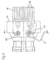
Firstly, an axial set movement of thenut 54 or theoverload cup 60, respectively, may be achieved by means of themotor 34, thegear unit 36, themotor shaft 50 and the threadedspindle 52 since thenut 54 is secured within the adaptor andtolerance ring 66 against rotation, and the adaptor andtolerance ring 66 on its behalf is secured against rotation in a manner still to be described. Secondly, when themain housing 10 and thecontrol housing 12 are removed, thereception housing 38 for themotor 34 can be manually rotated so that a normal hand setting of the valve is possible. Thirdly, when themain housing 10 and thecontrol housing 12 are also removed, the adaptor andtolerance ring 66 can be rotated via theaccessible knurling 74, which results in an axial set movement of theoverload cup 60 acting upon the not shown valve stem. - Fig. 3 shows the motorized drive unit in its assembled state, wherat only the important portions are provided with reference numbers. From this figure and from the sectional view according to Fig. 6 it may be taken that the
drive housing 32 comprises a cut-out 94, by means of which theknurling 74 is accessible in order to manually adjust the adaptor andtolerance ring 66, whereat alatch 92 at aresilient portion 90 of thedrive housing 32 counteracts to this setting and prevents at a motorized or a manual setting, respectively, of the total unit a relative rotation between the adaptor andtolerance ring 66 and thedrive housing 32. - From Fig. 4 it may be taken that the
reception housing 38 comprises a cut-out 96 which is matched to the shape and dimension of the motor or gear unit, respectively, in order to mount and to secure against rotation those drive units within thereception housing 38. - From Fig. 5 it may be taken that the
reception housing 38 is provided at its U-circumference withindentations 98 to make rotatable thereception housing 38 at its manual setting in the same manner as a handle. The mountinglever 30 is supported by means of ascrew 100 at thedrive housing 32 and if required can be positioned in the other position as provided by the screw 100'.
Claims (11)
- A radiator valve control device arranged to be flange-mounted to a radiator valve in order to axially displace a valve stem of said radiator valve comprising a motorized drive unit and a main housing accommodating said motorized drive unit and having operating means, display means, control means and power supply means, characterized by the following features:A. the motorized drive unit comprisesa) a reception housing (38) accommodating a motor (34), andb) a stationary drive housing (32), whereatc) said reception housing (38) is rotatably flange-mounted to said drive housing (32), andB. the main housing (10) comprisesd) a cut-out (24), which is engaged by said reception housing (38) when the main housing is locked to the stationary drive housing (32), with said cut-out (24) and said reception housing (38) being shaped to prevent relative rotation of the main housing (10) and of the reception housing when both are locked to each other but allowing rotation of said reception housing when the main housing is removed from said stationary drive housing and from said reception housing.
- Device according to claim 1, characterized in that said cut-out (24) and said reception housing (32) have a U-shape.
- Device according to claim 2 with said motor (34) acting via a gear unit (36) on a driving shaft (50), characterized in that said driving shaft (50) is drivingly connected via a position indicator (48) to a threaded spindle (52), whereat said threaded spindle (52) on its behalf engages a nut (54) which is secured against rotation in an adapter and tolerance ring (66).
- Device according to claim 3, characterized in that the nut (54) abuts via an overload spring (58) against a cup-shaped bushing (60) with said bushing being in driving connection with the valve stem of the radiator valve.
- Device according to claim 4, characterized in that the nut (54) comprises a radially extending pin (56) which engages a groove (68) in the adaptor and tolerance ring (66) via a groove (70) in the cup-shaped bushing (60).
- Device according to claim 3, characterized in that the adaptor and tolerance ring (66) is rotatably supported in said drive housing (32) flange-mounted to the radiator valve, whereat for locking a knurling (74) at the circumference of the adaptor and tolerance ring (66) acts together with a resilient latch (92) at the drive housing (32).
- Device according to claim 6, characterized in that a mounting lever (30) is supported at the drive housing (32) serving to lock the main housing (10) to the motorized drive unit (30-84) in its slipped-on state.
- Device according to one of claims 1 to 7, comprising batteries in a power supply portion, characterized in that the power supply portion is a battery plug-in unit (18) which is insertable from the backside of the main housing (10).
- Device according to claim 8, characterized in that the battery plug-in unit (18) extends parallel to the motorized drive unit (30-84).
- Device according to claim 9, characterized in that the main housing (10) comprises an apron (26) which overlaps a flange connection (80,86) between the motorized drive unit and the radiator valve.
- Device according to claim 7, characterized in that the mounting lever (30) may be mounted in two positions (100,100') at the drive housing (32) with said two positions being symmetrically arranged with respect to the longitudinal axis.
Priority Applications (1)
| Application Number | Priority Date | Filing Date | Title |
|---|---|---|---|
| AT88900220T ATE83566T1 (en) | 1986-12-10 | 1987-12-07 | CONTROL DEVICE FOR A RADIATOR VALVE. |
Applications Claiming Priority (2)
| Application Number | Priority Date | Filing Date | Title |
|---|---|---|---|
| DE19863642113 DE3642113A1 (en) | 1986-12-10 | 1986-12-10 | ACTUATING DEVICE FOR A RADIATOR VALVE |
| DE3642113 | 1986-12-10 |
Publications (2)
| Publication Number | Publication Date |
|---|---|
| EP0333763A1 EP0333763A1 (en) | 1989-09-27 |
| EP0333763B1 true EP0333763B1 (en) | 1992-12-16 |
Family
ID=6315840
Family Applications (1)
| Application Number | Title | Priority Date | Filing Date |
|---|---|---|---|
| EP19880900220 Expired - Lifetime EP0333763B1 (en) | 1986-12-10 | 1987-12-07 | Control device for a radiator valve |
Country Status (10)
| Country | Link |
|---|---|
| US (1) | US5137051A (en) |
| EP (1) | EP0333763B1 (en) |
| JP (1) | JPH02503026A (en) |
| AT (1) | ATE83566T1 (en) |
| CA (1) | CA1289932C (en) |
| DE (2) | DE3642113A1 (en) |
| DK (1) | DK169223B1 (en) |
| ES (1) | ES2005727A6 (en) |
| FI (1) | FI91921C (en) |
| WO (1) | WO1988004447A1 (en) |
Families Citing this family (25)
| Publication number | Priority date | Publication date | Assignee | Title |
|---|---|---|---|---|
| DE3834438C1 (en) * | 1988-10-10 | 1989-09-07 | Theodor Heimeier Metallwerk Kg, 4782 Erwitte, De | Heating-system valve with a thermally influenceable regulating drive |
| DE4118966A1 (en) * | 1991-06-08 | 1992-12-10 | Karl Thiel | Thermostat room heating control adjusting heating valve - has common housing for control and function elements allowing full disconnection of operating current |
| CN2150416Y (en) * | 1993-01-11 | 1993-12-22 | 黄建达 | Water tap with liquid crystal temp. display |
| DE4412226C2 (en) * | 1994-04-09 | 1997-09-11 | Ziegler Horst | Program control for a thermostatic valve or heating control |
| DE19706736C1 (en) * | 1997-02-20 | 1998-06-04 | Honeywell Ag | Motor-based actuator for central heating thermostatic valves |
| DE19710800A1 (en) * | 1997-03-17 | 1998-10-01 | Ideal Standard | Electrically operated fitting |
| DE19754837A1 (en) * | 1997-12-10 | 1999-07-15 | Danfoss As | Thermostatic attachment for a valve |
| US6186471B1 (en) | 1998-05-15 | 2001-02-13 | Taco, Inc. | Electronic motorized zone valve |
| DE19909100C2 (en) * | 1999-03-02 | 2002-02-07 | Danfoss As | Thermostatic valve top |
| DE19909102C2 (en) * | 1999-03-02 | 2001-10-04 | Danfoss As | Control device for a heating device |
| DE19909101C2 (en) * | 1999-03-02 | 2001-06-28 | Danfoss As | Control unit for a thermostatic valve attachment |
| DE19909099C2 (en) * | 1999-03-02 | 2002-02-07 | Danfoss As | Heating valve thermostat top |
| DE10065098B4 (en) * | 2000-12-28 | 2004-01-22 | F.W. Oventrop Gmbh & Co. Kg | Adjustment device for valves |
| DE10257082B8 (en) * | 2002-12-06 | 2005-03-03 | Techem Development Gmbh | actuator |
| DE20304439U1 (en) * | 2003-03-19 | 2004-07-22 | Körner, Hans-Holger | Valve with electromotive drive for fluid-operated heating and cooling systems |
| DE102004012620A1 (en) * | 2004-03-12 | 2005-09-29 | Kahlert, Gabriele | Thermostat valve for a heating body comprises a turning handle with a device for controlling the temperature of the heating body, and an externally readable thermometer attached to the valve and not coupled to the heating medium temperature |
| DE102004048366B4 (en) * | 2004-10-01 | 2007-10-25 | Auma Riester Gmbh & Co. Kg | Actuator for actuating a valve in process automation |
| DE102005038067B4 (en) * | 2005-08-10 | 2008-12-11 | Danfoss A/S | Valve attachment for a valve, in particular heating or cooling valve |
| CZ301151B6 (en) * | 2007-11-27 | 2009-11-18 | Microrisc S. R. O. | Device for controlling valves of heating system radiators |
| CZ18203U1 (en) * | 2007-11-28 | 2008-01-21 | Microrisc S. R. O. | Device to control valves of heating system radiators |
| DE202010007399U1 (en) | 2010-05-31 | 2010-09-09 | F.W. Oventrop Gmbh & Co. Kg | Display for electronic radiator thermostats |
| DE102010022399A1 (en) | 2010-06-01 | 2011-12-01 | Dieter Herber | Controlling device for controlling heating or cooling medium, particularly heater controller, has rotary drive and position element for opening and closing valve |
| DE102010024280B4 (en) | 2010-06-18 | 2012-11-22 | Diehl Ako Stiftung & Co. Kg | Adjusting device, in particular for a radiator valve |
| US9551999B2 (en) * | 2015-05-15 | 2017-01-24 | Yung Shen Gas Appliance Co., Ltd. | Structure of gas regulator |
| CN107166491A (en) * | 2017-06-13 | 2017-09-15 | 芜湖桑乐金电子科技有限公司 | The portable heating picture and long-range control method of remote control |
Citations (1)
| Publication number | Priority date | Publication date | Assignee | Title |
|---|---|---|---|---|
| US499786A (en) * | 1893-06-20 | Emory jacob godman |
Family Cites Families (12)
| Publication number | Priority date | Publication date | Assignee | Title |
|---|---|---|---|---|
| US2943706A (en) * | 1956-02-10 | 1960-07-05 | Specialties Dev Corp | Quick acting valve operating mechanism |
| US2977437A (en) * | 1959-12-24 | 1961-03-28 | Daniel B Doane | Electrically actuated rotary valve for zone heat control |
| US3680831A (en) * | 1969-06-07 | 1972-08-01 | Katsuji Fujiwara | Electrically driven valve apparatus |
| JPS4930109A (en) * | 1972-07-29 | 1974-03-18 | ||
| JPS57791B2 (en) * | 1973-11-23 | 1982-01-07 | ||
| US4000663A (en) * | 1974-08-22 | 1977-01-04 | Robertshaw Controls Company | Damper actuator |
| FR2486678B1 (en) * | 1980-07-09 | 1985-06-14 | Valeo | DEVICE FOR CONTROLLING AN ELEMENT ROTATED AROUND AN AXIS, IN PARTICULAR IN A HEATING AND / OR AIR CONDITIONING INSTALLATION OF A MOTOR VEHICLE INTERIOR |
| AT379672B (en) * | 1983-01-21 | 1986-02-10 | Schrack Elektronik Ag | CONTROL VALVE FOR RADIATOR |
| AT383660B (en) * | 1984-05-03 | 1987-08-10 | Schrack Elektronik Ag | CONTROL VALVE |
| DE3416970A1 (en) * | 1984-05-08 | 1985-11-14 | Hans 8025 Unterhaching Lechner | Control valve |
| DE3509353C1 (en) * | 1985-03-15 | 1986-06-12 | Polytronic Kunststoff-Elektro Gmbh, 4796 Salzkotten | Regulating device for a thermostat valve |
| US4647007A (en) * | 1986-02-24 | 1987-03-03 | Peter Bajka | Valve actuator with manual disengagement assembly |
-
1986
- 1986-12-10 DE DE19863642113 patent/DE3642113A1/en not_active Withdrawn
-
1987
- 1987-12-07 JP JP63500536A patent/JPH02503026A/en active Pending
- 1987-12-07 EP EP19880900220 patent/EP0333763B1/en not_active Expired - Lifetime
- 1987-12-07 WO PCT/EP1987/000760 patent/WO1988004447A1/en active IP Right Grant
- 1987-12-07 US US07/350,473 patent/US5137051A/en not_active Expired - Fee Related
- 1987-12-07 AT AT88900220T patent/ATE83566T1/en not_active IP Right Cessation
- 1987-12-07 DE DE19873783138 patent/DE3783138T2/en not_active Expired - Fee Related
- 1987-12-09 CA CA 553868 patent/CA1289932C/en not_active Expired - Lifetime
- 1987-12-09 ES ES8703514A patent/ES2005727A6/en not_active Expired
-
1988
- 1988-08-10 DK DK447888A patent/DK169223B1/en not_active IP Right Cessation
-
1989
- 1989-06-09 FI FI892842A patent/FI91921C/en not_active IP Right Cessation
Patent Citations (1)
| Publication number | Priority date | Publication date | Assignee | Title |
|---|---|---|---|---|
| US499786A (en) * | 1893-06-20 | Emory jacob godman |
Also Published As
| Publication number | Publication date |
|---|---|
| FI892842A (en) | 1989-06-09 |
| DE3783138D1 (en) | 1993-01-28 |
| DE3783138T2 (en) | 1993-04-22 |
| FI892842A0 (en) | 1989-06-09 |
| DK447888D0 (en) | 1988-08-10 |
| EP0333763A1 (en) | 1989-09-27 |
| FI91921C (en) | 1994-08-25 |
| DK169223B1 (en) | 1994-09-12 |
| FI91921B (en) | 1994-05-13 |
| US5137051A (en) | 1992-08-11 |
| JPH02503026A (en) | 1990-09-20 |
| CA1289932C (en) | 1991-10-01 |
| DE3642113A1 (en) | 1988-06-16 |
| ATE83566T1 (en) | 1993-01-15 |
| DK447888A (en) | 1988-08-10 |
| WO1988004447A1 (en) | 1988-06-16 |
| ES2005727A6 (en) | 1989-03-16 |
Similar Documents
| Publication | Publication Date | Title |
|---|---|---|
| EP0333763B1 (en) | Control device for a radiator valve | |
| EP0064602A2 (en) | Automatic door locking/unlocking device for an automotive vehicle | |
| US5768942A (en) | Drive device for a movable motor vehicle part | |
| EP0709167B1 (en) | Tube wrench | |
| CA2279729A1 (en) | Movable handle for a power tool | |
| AU2577392A (en) | Shaft lock arrangement for a power tool | |
| AU2021218075B2 (en) | Pcb with integrated switches | |
| US5634815A (en) | Battery receiving mechanism | |
| CA2099998C (en) | Dial speed control for hand-held power tool | |
| US5244411A (en) | Electrical appliance | |
| US5012264A (en) | Coupling device and power device for supplying electrical power as the coupling is established | |
| US5489755A (en) | Handle operator assembly for high ampere-rated circuit breaker | |
| US5252791A (en) | Ignition switch | |
| US20030209042A1 (en) | Electronically operated lock | |
| CN211667433U (en) | Lens angle adjusting mechanism and monitoring device | |
| US4912380A (en) | Field installable electrical operator for a circuit breaker | |
| US4334132A (en) | Switch with shaft positioning arrangement | |
| US4910443A (en) | Electronic control circuit for a bidirectional motor | |
| US4471338A (en) | Thermal cycling switch | |
| BG102889A (en) | Device for electrical control of locking/unloading of a lock having an antipanic function containing the device | |
| JPH06296773A (en) | Electrical appliance | |
| US20030126936A1 (en) | Automated gear selection apparatus | |
| US4719323A (en) | Simplified vehicle lighting switch | |
| JP2597790Y2 (en) | Motor with reduction mechanism | |
| SU1108524A1 (en) | Drive of circuit breaker for power transformer |
Legal Events
| Date | Code | Title | Description |
|---|---|---|---|
| PUAI | Public reference made under article 153(3) epc to a published international application that has entered the european phase |
Free format text: ORIGINAL CODE: 0009012 |
|
| 17P | Request for examination filed |
Effective date: 19890420 |
|
| AK | Designated contracting states |
Kind code of ref document: A1 Designated state(s): AT BE CH DE FR GB IT LI LU NL SE |
|
| RBV | Designated contracting states (corrected) |
Designated state(s): AT BE CH DE FR GB IT LI NL SE |
|
| 17Q | First examination report despatched |
Effective date: 19920518 |
|
| GRAA | (expected) grant |
Free format text: ORIGINAL CODE: 0009210 |
|
| AK | Designated contracting states |
Kind code of ref document: B1 Designated state(s): AT BE CH DE FR GB IT LI NL SE |
|
| REF | Corresponds to: |
Ref document number: 83566 Country of ref document: AT Date of ref document: 19930115 Kind code of ref document: T |
|
| ET | Fr: translation filed | ||
| REF | Corresponds to: |
Ref document number: 3783138 Country of ref document: DE Date of ref document: 19930128 |
|
| ITF | It: translation for a ep patent filed |
Owner name: BARZANO' E ZANARDO ROMA S.P.A. |
|
| PLBE | No opposition filed within time limit |
Free format text: ORIGINAL CODE: 0009261 |
|
| STAA | Information on the status of an ep patent application or granted ep patent |
Free format text: STATUS: NO OPPOSITION FILED WITHIN TIME LIMIT |
|
| 26N | No opposition filed | ||
| PGFP | Annual fee paid to national office [announced via postgrant information from national office to epo] |
Ref country code: GB Payment date: 19940920 Year of fee payment: 8 |
|
| EAL | Se: european patent in force in sweden |
Ref document number: 88900220.0 |
|
| PG25 | Lapsed in a contracting state [announced via postgrant information from national office to epo] |
Ref country code: GB Effective date: 19951207 |
|
| GBPC | Gb: european patent ceased through non-payment of renewal fee |
Effective date: 19951207 |
|
| PGFP | Annual fee paid to national office [announced via postgrant information from national office to epo] |
Ref country code: AT Payment date: 20051104 Year of fee payment: 19 |
|
| PGFP | Annual fee paid to national office [announced via postgrant information from national office to epo] |
Ref country code: NL Payment date: 20051109 Year of fee payment: 19 |
|
| PGFP | Annual fee paid to national office [announced via postgrant information from national office to epo] |
Ref country code: FR Payment date: 20051201 Year of fee payment: 19 |
|
| PGFP | Annual fee paid to national office [announced via postgrant information from national office to epo] |
Ref country code: SE Payment date: 20051202 Year of fee payment: 19 |
|
| PGFP | Annual fee paid to national office [announced via postgrant information from national office to epo] |
Ref country code: CH Payment date: 20051216 Year of fee payment: 19 |
|
| PGFP | Annual fee paid to national office [announced via postgrant information from national office to epo] |
Ref country code: DE Payment date: 20051230 Year of fee payment: 19 |
|
| PGFP | Annual fee paid to national office [announced via postgrant information from national office to epo] |
Ref country code: BE Payment date: 20060113 Year of fee payment: 19 |
|
| REG | Reference to a national code |
Ref country code: CH Ref legal event code: PUE Owner name: HONEYWELL TECHNOLOGIES SARL Free format text: HONEYWELL AIRPORT SYSTEMS GMBH#INDUSTRIESTRASSE 23-33#22880 WEDEL (DE) -TRANSFER TO- HONEYWELL TECHNOLOGIES SARL#AVENUE DE LA GOTTAZ 34-36#1110 MORGES (CH) Ref country code: CH Ref legal event code: PFA Owner name: HONEYWELL AIRPORT SYSTEMS GMBH Free format text: CENTRA-BUERKLE GMBH#BOEBLINGER STRASSE 17#SCHOENAICH (DE) -TRANSFER TO- HONEYWELL AIRPORT SYSTEMS GMBH#INDUSTRIESTRASSE 23-33#22880 WEDEL (DE) |
|
| NLS | Nl: assignments of ep-patents |
Owner name: HONEYWELL TECHNOLOGIES SARL Effective date: 20060505 |
|
| NLT1 | Nl: modifications of names registered in virtue of documents presented to the patent office pursuant to art. 16 a, paragraph 1 |
Owner name: HONEYWELL AIRPORT SYSTEMS GMBH |
|
| REG | Reference to a national code |
Ref country code: FR Ref legal event code: TP Ref country code: FR Ref legal event code: CD Ref country code: FR Ref legal event code: CA |
|
| PG25 | Lapsed in a contracting state [announced via postgrant information from national office to epo] |
Ref country code: SE Free format text: LAPSE BECAUSE OF NON-PAYMENT OF DUE FEES Effective date: 20061208 |
|
| PG25 | Lapsed in a contracting state [announced via postgrant information from national office to epo] |
Ref country code: LI Free format text: LAPSE BECAUSE OF NON-PAYMENT OF DUE FEES Effective date: 20061231 Ref country code: CH Free format text: LAPSE BECAUSE OF NON-PAYMENT OF DUE FEES Effective date: 20061231 Ref country code: BE Free format text: LAPSE BECAUSE OF NON-PAYMENT OF DUE FEES Effective date: 20061231 |
|
| PGFP | Annual fee paid to national office [announced via postgrant information from national office to epo] |
Ref country code: IT Payment date: 20061231 Year of fee payment: 20 |
|
| PG25 | Lapsed in a contracting state [announced via postgrant information from national office to epo] |
Ref country code: NL Free format text: LAPSE BECAUSE OF NON-PAYMENT OF DUE FEES Effective date: 20070701 |
|
| PG25 | Lapsed in a contracting state [announced via postgrant information from national office to epo] |
Ref country code: DE Free format text: LAPSE BECAUSE OF NON-PAYMENT OF DUE FEES Effective date: 20070703 |
|
| REG | Reference to a national code |
Ref country code: CH Ref legal event code: PL |
|
| EUG | Se: european patent has lapsed | ||
| NLV4 | Nl: lapsed or anulled due to non-payment of the annual fee |
Effective date: 20070701 |
|
| REG | Reference to a national code |
Ref country code: FR Ref legal event code: ST Effective date: 20070831 |
|
| PG25 | Lapsed in a contracting state [announced via postgrant information from national office to epo] |
Ref country code: AT Free format text: LAPSE BECAUSE OF NON-PAYMENT OF DUE FEES Effective date: 20061207 |
|
| BECA | Be: change of holder's address |
Owner name: *HONEYWELL TECHNOLOGIES SARLAVENUE DE LA GOTTAZ 34 Effective date: 20060427 |
|
| BECH | Be: change of holder |
Owner name: *HONEYWELL TECHNOLOGIES SARL Effective date: 20060427 |
|
| BERE | Be: lapsed |
Owner name: *HONEYWELL TECHNOLOGIES SARL Effective date: 20061231 |
|
| PG25 | Lapsed in a contracting state [announced via postgrant information from national office to epo] |
Ref country code: FR Free format text: LAPSE BECAUSE OF NON-PAYMENT OF DUE FEES Effective date: 20070102 |