EP0333726B1 - Beutelherstellungsmaschine - Google Patents
Beutelherstellungsmaschine Download PDFInfo
- Publication number
- EP0333726B1 EP0333726B1 EP87907458A EP87907458A EP0333726B1 EP 0333726 B1 EP0333726 B1 EP 0333726B1 EP 87907458 A EP87907458 A EP 87907458A EP 87907458 A EP87907458 A EP 87907458A EP 0333726 B1 EP0333726 B1 EP 0333726B1
- Authority
- EP
- European Patent Office
- Prior art keywords
- machine
- roller
- web
- cutting means
- lines
- Prior art date
- Legal status (The legal status is an assumption and is not a legal conclusion. Google has not performed a legal analysis and makes no representation as to the accuracy of the status listed.)
- Expired - Lifetime
Links
Images

Classifications
-
- B—PERFORMING OPERATIONS; TRANSPORTING
- B31—MAKING ARTICLES OF PAPER, CARDBOARD OR MATERIAL WORKED IN A MANNER ANALOGOUS TO PAPER; WORKING PAPER, CARDBOARD OR MATERIAL WORKED IN A MANNER ANALOGOUS TO PAPER
- B31B—MAKING CONTAINERS OF PAPER, CARDBOARD OR MATERIAL WORKED IN A MANNER ANALOGOUS TO PAPER
- B31B70/00—Making flexible containers, e.g. envelopes or bags
- B31B70/005—Making flexible containers, e.g. envelopes or bags involving a particular layout of the machinery or relative arrangement of its subunits
-
- B—PERFORMING OPERATIONS; TRANSPORTING
- B31—MAKING ARTICLES OF PAPER, CARDBOARD OR MATERIAL WORKED IN A MANNER ANALOGOUS TO PAPER; WORKING PAPER, CARDBOARD OR MATERIAL WORKED IN A MANNER ANALOGOUS TO PAPER
- B31B—MAKING CONTAINERS OF PAPER, CARDBOARD OR MATERIAL WORKED IN A MANNER ANALOGOUS TO PAPER
- B31B2155/00—Flexible containers made from webs
-
- B—PERFORMING OPERATIONS; TRANSPORTING
- B31—MAKING ARTICLES OF PAPER, CARDBOARD OR MATERIAL WORKED IN A MANNER ANALOGOUS TO PAPER; WORKING PAPER, CARDBOARD OR MATERIAL WORKED IN A MANNER ANALOGOUS TO PAPER
- B31B—MAKING CONTAINERS OF PAPER, CARDBOARD OR MATERIAL WORKED IN A MANNER ANALOGOUS TO PAPER
- B31B2160/00—Shape of flexible containers
- B31B2160/10—Shape of flexible containers rectangular and flat, i.e. without structural provision for thickness of contents
-
- B—PERFORMING OPERATIONS; TRANSPORTING
- B31—MAKING ARTICLES OF PAPER, CARDBOARD OR MATERIAL WORKED IN A MANNER ANALOGOUS TO PAPER; WORKING PAPER, CARDBOARD OR MATERIAL WORKED IN A MANNER ANALOGOUS TO PAPER
- B31B—MAKING CONTAINERS OF PAPER, CARDBOARD OR MATERIAL WORKED IN A MANNER ANALOGOUS TO PAPER
- B31B70/00—Making flexible containers, e.g. envelopes or bags
- B31B70/14—Cutting, e.g. perforating, punching, slitting or trimming
- B31B70/144—Cutting, e.g. perforating, punching, slitting or trimming using tools mounted on belts or chains
-
- B—PERFORMING OPERATIONS; TRANSPORTING
- B31—MAKING ARTICLES OF PAPER, CARDBOARD OR MATERIAL WORKED IN A MANNER ANALOGOUS TO PAPER; WORKING PAPER, CARDBOARD OR MATERIAL WORKED IN A MANNER ANALOGOUS TO PAPER
- B31B—MAKING CONTAINERS OF PAPER, CARDBOARD OR MATERIAL WORKED IN A MANNER ANALOGOUS TO PAPER
- B31B70/00—Making flexible containers, e.g. envelopes or bags
- B31B70/60—Uniting opposed surfaces or edges; Taping
- B31B70/64—Uniting opposed surfaces or edges; Taping by applying heat or pressure
- B31B70/642—Uniting opposed surfaces or edges; Taping by applying heat or pressure using sealing jaws or sealing dies
-
- B—PERFORMING OPERATIONS; TRANSPORTING
- B31—MAKING ARTICLES OF PAPER, CARDBOARD OR MATERIAL WORKED IN A MANNER ANALOGOUS TO PAPER; WORKING PAPER, CARDBOARD OR MATERIAL WORKED IN A MANNER ANALOGOUS TO PAPER
- B31B—MAKING CONTAINERS OF PAPER, CARDBOARD OR MATERIAL WORKED IN A MANNER ANALOGOUS TO PAPER
- B31B70/00—Making flexible containers, e.g. envelopes or bags
- B31B70/60—Uniting opposed surfaces or edges; Taping
- B31B70/64—Uniting opposed surfaces or edges; Taping by applying heat or pressure
- B31B70/649—Uniting opposed surfaces or edges; Taping by applying heat or pressure using tools mounted on a drum
Definitions
- the present invention relates to a bag-making machine for forming bag-defining lines of perforation and weld lines in an elongate web, said machine comprising a driven roller nip including a nip roller and a back-up roller, by means of which the web can be fed into and through the machine, elongate cutting means disposed parallel to said rollers and rotatable about its longitudinal axis, said cutting means being movable into engagement with said back-up roller for making said lines of perforation, and a welding station comprising sealing jaws which are displaceable in the direction of travel of the web and movable into engagement with the web for making said weld lines as the web is moving.
- the technique on which this invention is based is represented by a known bag-making machine into the upper part of which an elongate web is fed by means of a roller nip consisting of two rollers.
- a roller nip consisting of two rollers.
- Parallel to one roller, the back-up roller there is mounted an elongate knife or cutter which is rotatable about its longitudinal axis and whose cutting edge, when rotated, impinges on the back-up roller for producing the lines of perforation in the web passing over the roller.
- the rotary knife thus impinges on the back-up roller once per revolution and thus produces lines of perforation which, by the continuous feed of the web, will be provided with predetermined spacings for forming bag lengths.
- the web After being perforated, the web passes vertically down through the machine past a welding station comprising sealing jaws which are moved in the direction of travel of the web and brought into engagement with the web for making weld lines as the web is moving.
- the knife and the welding station are mechanically interconnected by means of a chain transmission, which entails a number of drawbacks.
- the operation of the knife and, thus, of the welding station is controlled by an angle sensor connected to the nip roller and measuring the speed of the web or the web length passing the nip roller. Since the knife and the welding station are connected to each other by means of a common chain transmission, it is not possible to set the spacing between the lines of perforation and the weld lines when the machine is in operation. Further, the stop position of the knife before impinging on the back-up roller is conditioned by neither the knife nor any sealing jaw being in contact with the web in the stop position.
- the stop position of the knife is limited, in constructional respect, to a maximum so-called impact angle of about 45°. This means that the angle through which the knife edge is decelerated and accelerated before impact varies, which means that at high web speeds the knife will not have time to attain an optimal angular velocity at the impact.
- a drawback is that the knife and the welding station must be arranged relatively close to each other, which entails that the stop position of the knife before the impact is such that the knife edge is situated near the back-up roller and that the angle through which the knife is accelerated becomes limited.
- a target value of the angle between the stop position of the knife and its impact position is, as stated above, at most about 45°.
- a further drawback of the known bag-making machine, which has only one knife, is that the minimum bag length that can be produced is mathematically determined, i.e. the circumference of the circular arc which the knife edge describes during its rotation; in mathematical terms, 2 ⁇ x the distance between the centre of rotation of the knife and the knife edge.
- the known bag-making machine has proved too slow in operation considering the new bag-making materials which have been developed in recent years. With these materials, the extruder in which the material is extruded into a so-called hose must be run at a higher speed, which means that also the succeeding machines in a production line, e.g. the bag-making machine, must be run at a higher speed. Thus, there is a need for a fast-operating bag-making machine which can stand up to the required increase of the web velocity and, thus, provide an increase in production obtained with the new materials.
- the present invention has for its object to overcome the above-mentioned drawbacks by providing a fast-operating arrangement which is intended for a bag-making machine and the operation of which is mechanically independent of other transmissions or means in the bag-making machine and which allows optional adjustment of the relative spacing between the lines of perforation and, also, the spacing between these lines and adjacent weld lines.
- Another object of the invention is to ensure that the stop position of the cutting means, before impinging on the back-up roller, should be adjustable for optimizing the speed of the knife edge at the impact.
- a further object is to make it possible to produce relatively short bags independently of the operation of the cutting means or its mechanical dependence on the other components of the bag-making machine.
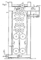
- Fig. 1 shows the bag-making machine and the arrangement according to the invention included therein schematically from in front.
- Fig. 2 shows the bag-making machine in a side view taken along the line-II-II in Fig. 1.
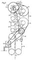
- Fig. 3 shows the transmissions of the bag-making machine in a side view taken along the line III-III in Fig. 1.
- Fig. 1 shows a bag-making machine 1 including the arrangement according to the invention and having a perforation, welding and cooling unit 2 and a transmission unit 3.
- a roller nip with a nip roller 4 and a back-up roller 5 which are mounted in a frame 6.
- a web 7, preferably of plastic material is fed into the machine 1 by means of the rollers 4, 5 and passes vertically downwards via two similar welding units 8 and a cooling station 9 to be further described hereinbelow.
- a cutting means 10 which is rotatably mounted in the frame 6 and has two similar, diametrically disposed, exchangeable knives 11 which, when the cutting means 10 is rotated, are caused to impinge on the web 7 passing over the back-up roller 5, for producing transverse lines of perforation 12.
- the spacing between two consecutive lines of perforation 12 thus defines a bag length.
- the edge of each knife 11 is provided with teeth in a known manner.
- an angle sensor 13 measuring the web length fed into the machine 1.
- the angle sensor 13 emits signals to the cutting means 10 in a way to be described in more detail hereinbelow.
- the transmission unit 3 includes three similar, fast-operating, separately connectible and disconnectible step couplings, the first 14 of which drives the cutting means 10 while the other two 15, 16 each drive a welding unit 8.
- the step couplings 14, 15, 16 are driven by an electric motor 17 via a drive transmission 18 in the form of a toothed belt and a coupling transmission 19, also in the form of a toothed belt.
- the toothed belts mesh with external teeth on the couplings 14, 15, 16.
- the transmissions 18, 19 may of course consist of other drive means in the form of endless loops, e.g. chains.
- Fig. 2 clearly illustrates the function of the bag-making machine 1 during operation.
- the web 7 is fed in a known manner into the machine via a guide roller 20 and a hingedly mounted floating roller 21.
- the web 7 is thereafter perforated by means of the rotating cutting means 10 and thereafter passes to the welding units 8 each of which comprises two opposing chain and guide pulley devices which are previously known and therefore not described in more detail here.
- these devices include transverse sealing jaws 22 which are moved into engagement with each other so as to clamp the web 7 descending through the machine 1.
- the sealing jaws 22 have electric conductors producing weld lines 12′ adjacent the lines of perforation 12 produced by the knives 11.
- the arrangement is such that the upper welding unit 8 produces weld lines 12′ at the lines of perforation 12 made by one knife 11 while the lower welding unit 8 produces weld lines at the lines of perforation 12 made by the other knife 11.
- the cooling station generally designated 9, which is of known type and therefore will not be described in more detail here.
- Fig. 3 the transmission unit 3 is shown in more detail.
- the above-mentioned toothed belts 18, 19 for driving the step couplings 14, 15, 16 are indicated by full, bold lines.
- the chain drives 24, 25 are of conventional type and will therefore not be described in more detail.
- one object of the invention is to make the cutting means 10 and the welding units 8 independent of other transmissions included in the machine 1 for allowing optional adjustment of the spacing between consecutive lines of perforation 12 and adjacent weld lines 12′.
- the angle sensor 13 connected to the nip roller 4 measures the web length fed into the machine and thereafter, via an electric control equipment (not shown), emits signals to the step coupling 14 which very quickly activates or connects the cutting means 10 such that one knife 11 is rapidly accelerated from stop position to impact position and thereafter decelerated.
- the step coupling 14 is automatically disconnected after half a revolution by means of a schematically shown photo cell 26 included in the coupling.
- the step couplings 15, 16 are also connected for operating the welding units 8.
- the two step couplings 15, 16 associated with the welding units 8 have photo cells 26 for interrupting operation. In this manner, it is ensured that the weld lines 12′ produced in the welding units 8 are correctly positioned in relation to the lines of perforation 12 made by the knives 11.
- the so-called flag i.e. the spacing between a line of perforation 12 and a weld line 12′, can be set with great accuracy, even when the machine 1 is in operation. This is a major advantage over known bag-making machines where the operation of the knife and the welding station is controlled by one and the same coupling.
- the bag length can be halved if so desired, as compared with the possibilities in known bag-making machines.
- the minimum bag length instead becomes f x the spacing between the centre of rotation of the cutting means 10 and the knife edges.
- the cutting means 10 is shown with its upper knife 11 in the stop position making a certain angle with the point of impact on the back-up roller 5.
- the angle here called impact angle ⁇
- the knife 11 is accelerated when rotated towards the back-up roller 5 and, optimally, the angle velocity of the knife is constant at the very impact.
- the movement of the knife 11 is thereafter decelerated, preferably through an equally large angle.
- the knives 11 change places in connection with each impact.
- the impact angle in known bag-making machines is of the order of 45° or less. In such cases, the knife will not have time to attain a constant angular velocity, which is necessary to have the perforation made in a reliable way. This limits the speed of operation of the known machine.
- the cutting means 10 operates in such a manner that, for each impact, the angle of rotation of the two knives 11 is divided into an angle of acceleration and a substantially equally large angle of deceleration. It is evident that the knife 11 will thus have a constant angular velocity when impinging on the back-up roller 5.
- step couplings 14, 15, 16 essential to the arrangement according to the invention are pneumatic and, as stated above, extremely quick-acting. Connection and disconnection of the step coupling 14 for controlling the rotation of the cutting means 10 is carried out in a very short time, about 10-20 ⁇ s, and with very high accuracy.
- the cutting means 10 here described has two knives 11, it is of course conceivable to use only one knife or several knives.
- the cutting means 10 is preferably controlled in such a manner that its impact angle ⁇ is in the range of 45-270° and preferably about 180°. It is evident that an impact angle ⁇ of 180° implies that the cutting means 10 is rotated one revolution for each impact. If the cutting means 10 has three or four knives, these are distributed equiangularly on the cutting means 10 in such a manner that their stop position before impact, i.e. the impact angle ⁇ is at least 45° for the same reason as stated in the foregoing.
- the cutting means can be provided with other types of knives, and other step couplings can be used.
- the inventive principle however remains the same, i.e. that the cutting means 10 and the welding units 8 should be separately connectible and disconnectible independently of other drive means.
Landscapes
- Making Paper Articles (AREA)
Claims (9)
Applications Claiming Priority (2)
| Application Number | Priority Date | Filing Date | Title |
|---|---|---|---|
| SE8604756A SE452131B (sv) | 1986-11-05 | 1986-11-05 | Anordning vid pasmaskin for bildande av pasavgrensande perforeringslinjer och svetslinjer |
| SE8604756 | 1986-11-05 |
Publications (2)
| Publication Number | Publication Date |
|---|---|
| EP0333726A1 EP0333726A1 (de) | 1989-09-27 |
| EP0333726B1 true EP0333726B1 (de) | 1991-10-16 |
Family
ID=20366205
Family Applications (1)
| Application Number | Title | Priority Date | Filing Date |
|---|---|---|---|
| EP87907458A Expired - Lifetime EP0333726B1 (de) | 1986-11-05 | 1987-11-05 | Beutelherstellungsmaschine |
Country Status (8)
| Country | Link |
|---|---|
| US (1) | US4950217A (de) |
| EP (1) | EP0333726B1 (de) |
| JP (1) | JPH0698719B2 (de) |
| BR (1) | BR8707866A (de) |
| DE (1) | DE3773943D1 (de) |
| DK (1) | DK168788B1 (de) |
| SE (1) | SE452131B (de) |
| WO (1) | WO1988003474A1 (de) |
Cited By (1)
| Publication number | Priority date | Publication date | Assignee | Title |
|---|---|---|---|---|
| EP0844070A1 (de) | 1996-11-26 | 1998-05-27 | Kraft Foods, Inc. | Verfahren und Vorrichtung zum Trennen von individuellen Bahnabschnitten |
Families Citing this family (8)
| Publication number | Priority date | Publication date | Assignee | Title |
|---|---|---|---|---|
| EP0537127A1 (de) * | 1991-09-06 | 1993-04-14 | Fas Converting Machinery Aktiebolag | Verfahren und Vorrichtung zur Herstellung von Querschweissnähten an Kunststoffolien-Materialbahnen |
| US5215514A (en) * | 1991-09-06 | 1993-06-01 | Fas Converting Machinery Ab | Method and arrangement in a bag-making machine for forming weld lines in a web fed therethrough |
| US5334126A (en) * | 1993-02-10 | 1994-08-02 | Moll Richard J | Controlled perforation apparatus for folding machines |
| SE506084C2 (sv) * | 1995-02-21 | 1997-11-10 | Fas Converting Machinery Ab | Anordning och förfarande för applicering av omslag på cylindriska påsrullar |
| JP2716024B2 (ja) * | 1995-11-24 | 1998-02-18 | 日本電気株式会社 | 先読み学習によるディジタルサーボ装置 |
| SE509343C2 (sv) * | 1997-05-02 | 1999-01-18 | Fas Converting Machinery Ab | Svetsenhet samt påsmaskin med sådan svetsenhet |
| SE515960C2 (sv) | 2000-03-16 | 2001-11-05 | Fas Converting Machinery Ab | Förfarande och maskin för bearbetning av en långsträckt materialbana |
| JP4868670B2 (ja) * | 2001-09-26 | 2012-02-01 | トタニ技研工業株式会社 | 製袋機 |
Family Cites Families (4)
| Publication number | Priority date | Publication date | Assignee | Title |
|---|---|---|---|---|
| US3147168A (en) * | 1961-03-06 | 1964-09-01 | Delamere & Williams Company Lt | Bag making machine and method |
| US3797368A (en) * | 1971-07-23 | 1974-03-19 | F Martelli | Rotary bag making apparatus |
| EP0023117A1 (de) * | 1979-07-11 | 1981-01-28 | Sulzer Bros (Uk) Ltd. | Maschinenantriebssysteme |
| US4500307A (en) * | 1981-10-23 | 1985-02-19 | Bridgeman Danial N P | Apparatus for producing continuous bags of thin wall material |
-
1986
- 1986-11-05 SE SE8604756A patent/SE452131B/sv not_active IP Right Cessation
-
1987
- 1987-11-05 EP EP87907458A patent/EP0333726B1/de not_active Expired - Lifetime
- 1987-11-05 WO PCT/SE1987/000518 patent/WO1988003474A1/en not_active Ceased
- 1987-11-05 US US07/347,043 patent/US4950217A/en not_active Expired - Lifetime
- 1987-11-05 JP JP62506852A patent/JPH0698719B2/ja not_active Expired - Lifetime
- 1987-11-05 DE DE8787907458T patent/DE3773943D1/de not_active Expired - Fee Related
- 1987-11-05 BR BR8707866A patent/BR8707866A/pt not_active IP Right Cessation
-
1988
- 1988-07-05 DK DK373988A patent/DK168788B1/da not_active IP Right Cessation
Cited By (3)
| Publication number | Priority date | Publication date | Assignee | Title |
|---|---|---|---|---|
| EP0844070A1 (de) | 1996-11-26 | 1998-05-27 | Kraft Foods, Inc. | Verfahren und Vorrichtung zum Trennen von individuellen Bahnabschnitten |
| GB2335160A (en) * | 1996-11-26 | 1999-09-15 | Molins Plc | Method and apparatus for obtaining individual web sections from a web of sheet material |
| GB2335160B (en) * | 1996-11-26 | 2000-11-15 | Molins Plc | Method and apparatus for obtaining individual web sections from a web of sheet material |
Also Published As
| Publication number | Publication date |
|---|---|
| EP0333726A1 (de) | 1989-09-27 |
| DE3773943D1 (de) | 1991-11-21 |
| JPH02500734A (ja) | 1990-03-15 |
| SE8604756D0 (sv) | 1986-11-06 |
| DK373988A (da) | 1988-07-05 |
| SE452131B (sv) | 1987-11-16 |
| DK168788B1 (da) | 1994-06-13 |
| US4950217A (en) | 1990-08-21 |
| BR8707866A (pt) | 1989-10-03 |
| JPH0698719B2 (ja) | 1994-12-07 |
| DK373988D0 (da) | 1988-07-05 |
| WO1988003474A1 (en) | 1988-05-19 |
Similar Documents
| Publication | Publication Date | Title |
|---|---|---|
| EP0333726B1 (de) | Beutelherstellungsmaschine | |
| US5496431A (en) | Method and system for changing product specifications in a corrugation machine | |
| US3942786A (en) | Sheet laying apparatus | |
| US3485128A (en) | Cutting of web material into strips | |
| US6729217B2 (en) | Device for breaking nicks connecting two edges of a cutting line | |
| CA1101780A (en) | Rotatable cutter mechanism for cutting different length notches in a moving web | |
| US4207787A (en) | Swatch cutting system | |
| US2670796A (en) | Apparatus for cutting strip | |
| EP0412835B1 (de) | Vorrichtung zum Transportieren und Schneiden von Produkten | |
| CN1054749A (zh) | 物品包装装置 | |
| US3800640A (en) | Apparatus and method for cutting a travelling web of material | |
| GB2050895A (en) | Improvements to machines for grooving sheets, particularly printed- circuit sheets | |
| US4184392A (en) | Web cutting machines | |
| US4109902A (en) | Apparatus for the continuous zigzag folding of a material web | |
| JPH0263729A (ja) | 製袋機 | |
| US5067698A (en) | Method and apparatus for manufacturing interfolded toweling | |
| CA1080610A (en) | Longitudinal cutting device | |
| US4221627A (en) | Device for connecting together steel cord inserts for vehicle tires | |
| US4068566A (en) | Universal bag-making machine | |
| US3508693A (en) | Automatic tearing device for continuous coupling machines | |
| US4693152A (en) | Rotary tube punching arrangement with tumbling punch and method for punching holes into a film web | |
| US3545323A (en) | Punching apparatus for work on continuously moving webs in bag-making machines | |
| US5215514A (en) | Method and arrangement in a bag-making machine for forming weld lines in a web fed therethrough | |
| EP0491666B1 (de) | Mechanismus zum Zuführen und Zerschneiden von Folienbahnen zur Verwendung in automatischen Verpackungsmaschinen | |
| US4759246A (en) | Tumbling hole punch and method for punching holes into a moving web material |
Legal Events
| Date | Code | Title | Description |
|---|---|---|---|
| PUAI | Public reference made under article 153(3) epc to a published international application that has entered the european phase |
Free format text: ORIGINAL CODE: 0009012 |
|
| 17P | Request for examination filed |
Effective date: 19890502 |
|
| AK | Designated contracting states |
Kind code of ref document: A1 Designated state(s): BE DE FR GB IT NL |
|
| 17Q | First examination report despatched |
Effective date: 19901204 |
|
| GRAA | (expected) grant |
Free format text: ORIGINAL CODE: 0009210 |
|
| AK | Designated contracting states |
Kind code of ref document: B1 Designated state(s): BE DE FR GB IT NL |
|
| ITF | It: translation for a ep patent filed | ||
| REF | Corresponds to: |
Ref document number: 3773943 Country of ref document: DE Date of ref document: 19911121 |
|
| PGFP | Annual fee paid to national office [announced via postgrant information from national office to epo] |
Ref country code: GB Payment date: 19911122 Year of fee payment: 5 Ref country code: FR Payment date: 19911122 Year of fee payment: 5 |
|
| PGFP | Annual fee paid to national office [announced via postgrant information from national office to epo] |
Ref country code: NL Payment date: 19911130 Year of fee payment: 5 |
|
| PGFP | Annual fee paid to national office [announced via postgrant information from national office to epo] |
Ref country code: BE Payment date: 19911211 Year of fee payment: 5 |
|
| ET | Fr: translation filed | ||
| PLBE | No opposition filed within time limit |
Free format text: ORIGINAL CODE: 0009261 |
|
| STAA | Information on the status of an ep patent application or granted ep patent |
Free format text: STATUS: NO OPPOSITION FILED WITHIN TIME LIMIT |
|
| 26N | No opposition filed | ||
| PG25 | Lapsed in a contracting state [announced via postgrant information from national office to epo] |
Ref country code: GB Effective date: 19921105 |
|
| PG25 | Lapsed in a contracting state [announced via postgrant information from national office to epo] |
Ref country code: BE Effective date: 19921130 |
|
| BERE | Be: lapsed |
Owner name: FAS CONVERTING MACHINERY A.B. Effective date: 19921130 |
|
| PG25 | Lapsed in a contracting state [announced via postgrant information from national office to epo] |
Ref country code: NL Effective date: 19930601 |
|
| GBPC | Gb: european patent ceased through non-payment of renewal fee |
Effective date: 19921105 |
|
| NLV4 | Nl: lapsed or anulled due to non-payment of the annual fee | ||
| PG25 | Lapsed in a contracting state [announced via postgrant information from national office to epo] |
Ref country code: FR Effective date: 19930730 |
|
| REG | Reference to a national code |
Ref country code: FR Ref legal event code: ST |
|
| PGFP | Annual fee paid to national office [announced via postgrant information from national office to epo] |
Ref country code: DE Payment date: 20011107 Year of fee payment: 15 |
|
| PG25 | Lapsed in a contracting state [announced via postgrant information from national office to epo] |
Ref country code: DE Free format text: LAPSE BECAUSE OF NON-PAYMENT OF DUE FEES Effective date: 20030603 |
|
| PG25 | Lapsed in a contracting state [announced via postgrant information from national office to epo] |
Ref country code: IT Free format text: LAPSE BECAUSE OF NON-PAYMENT OF DUE FEES;WARNING: LAPSES OF ITALIAN PATENTS WITH EFFECTIVE DATE BEFORE 2007 MAY HAVE OCCURRED AT ANY TIME BEFORE 2007. THE CORRECT EFFECTIVE DATE MAY BE DIFFERENT FROM THE ONE RECORDED. Effective date: 20051105 |