EP0332929B2 - Verfahren und Vorrichtung zur Wirbelschichtsprühgranulation - Google Patents
Verfahren und Vorrichtung zur Wirbelschichtsprühgranulation Download PDFInfo
- Publication number
- EP0332929B2 EP0332929B2 EP89103542A EP89103542A EP0332929B2 EP 0332929 B2 EP0332929 B2 EP 0332929B2 EP 89103542 A EP89103542 A EP 89103542A EP 89103542 A EP89103542 A EP 89103542A EP 0332929 B2 EP0332929 B2 EP 0332929B2
- Authority
- EP
- European Patent Office
- Prior art keywords
- zigzag
- fluidised bed
- spray nozzle
- fluidized bed
- approach
- Prior art date
- Legal status (The legal status is an assumption and is not a legal conclusion. Google has not performed a legal analysis and makes no representation as to the accuracy of the status listed.)
- Expired - Lifetime
Links
Images

Classifications
-
- B—PERFORMING OPERATIONS; TRANSPORTING
- B01—PHYSICAL OR CHEMICAL PROCESSES OR APPARATUS IN GENERAL
- B01J—CHEMICAL OR PHYSICAL PROCESSES, e.g. CATALYSIS OR COLLOID CHEMISTRY; THEIR RELEVANT APPARATUS
- B01J2/00—Processes or devices for granulating materials, e.g. fertilisers in general; Rendering particulate materials free flowing in general, e.g. making them hydrophobic
- B01J2/16—Processes or devices for granulating materials, e.g. fertilisers in general; Rendering particulate materials free flowing in general, e.g. making them hydrophobic by suspending the powder material in a gas, e.g. in fluidised beds or as a falling curtain
-
- B—PERFORMING OPERATIONS; TRANSPORTING
- B07—SEPARATING SOLIDS FROM SOLIDS; SORTING
- B07B—SEPARATING SOLIDS FROM SOLIDS BY SIEVING, SCREENING, SIFTING OR BY USING GAS CURRENTS; SEPARATING BY OTHER DRY METHODS APPLICABLE TO BULK MATERIAL, e.g. LOOSE ARTICLES FIT TO BE HANDLED LIKE BULK MATERIAL
- B07B4/00—Separating solids from solids by subjecting their mixture to gas currents
- B07B4/02—Separating solids from solids by subjecting their mixture to gas currents while the mixtures fall
- B07B4/04—Separating solids from solids by subjecting their mixture to gas currents while the mixtures fall in cascades
Definitions
- the invention is based on a process for producing granules with a narrow particle size distribution, in which the liquid starting product is sprayed into a fluidized bed, the finished granulate is discharged from the fluidized bed in a classifying manner according to the principle of zigzag screening, and the classifying air stream is divided into individual individual streams , which are each assigned a zigzag classifier module and a spray nozzle.
- the invention also relates to a device for carrying out the method.
- the granulate is produced in one process step from the liquid starting product, with a classifying discharge from the fluidized bed. External screening and grinding of oversize particles can therefore be dispensed with.
- a prerequisite for this process is a sifting discharge which releases the particles which have reached the desired particle size from the fluidized bed.
- a granulator with a circular cross-section in which the classifying discharge device is arranged in the middle of the fluidization tray (inflow tray).
- the inflow floor is formed by a perforated plate that has a denser perforation that increases from the inside to the outside. This ensures that the particles rise on the container wall and sink in the center.
- the granules are each arranged in a parallel or radial zone within one of the two through a return shaft (9, 18) placed on the zigzag sifter module (7, 17)
- Incoming flow zone zone restricted layer are thrown back into the fluidized bed (4), and a cross-mixing of the blown-out granules between the individual zones of the granule chamber is avoided, the relatively small grains at a relatively large distance and the large grains which have already grown to close to the discharge size in a relatively small amount Impact distance from the return shaft (9, 18) and that if necessary, a spray nozzle group is assigned to the individual individual flows.
- the modular subdivision of the granulation chamber enables a defined particle circulation, in which the fine particles are thrown back into the bed in a targeted manner, while the coarser particles near the return shaft enter the bed The fluidized bed falls back and is therefore seen more frequently. Cross-mixing between the individual zones of the granulation chamber is avoided by specifically blowing out the particles from the return shaft.
- the fluidized bed granulator used to carry out the method is modified according to the invention in such a way that the zigzag sifter used for the classifying discharge is subdivided into modules and that at least one spray nozzle on the inflow base is assigned to each zigzag sifter module and on each zigzag -Sifter module at the connection point to the inflow floor, a return shaft is placed.
- each zigzag sifter module is advantageously provided with an underflow weir at the connection point to the inflow floor, so that a backflow of the grains occurs at the entry point to the zigzag sifter.
- the fluidized bed granulator and the zigzag sifter modules have a rectangular cross section.
- the width B of the fluidized bed granulator is equal to the length 1 of a zigzag classifier channel and the length L of the fluidized bed granulator is an integral multiple of the width b of the zigzag classifier channel.
- An alternative embodiment is characterized in that only one spray nozzle is assigned to the zigzag sifter module, the sifter channel being ring-shaped and in that the return shaft placed on it concentrically surrounds the spray nozzle.
- filter elements for exhaust air purification are expediently arranged above the spray nozzles belonging to a zigzag sifter module.
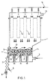
- the fluidized bed granulator shown schematically in FIG. 1 consists of a housing 1 with an inflow base 2, above which a fluidized bed 4 is maintained by means of a fluidizing gas 3.
- the liquid starting material from which the granules are to be produced is sprayed into the fluidized bed from below through the two-component nozzles 5.
- the diameter of the particles in the fluidized bed increases due to the sprayed and solidified material in shell-like fashion until they can pass through the classifying air flow 6 in the zigzag classifier module 7 and are discharged through the rotary valve 8.
- the smaller particles, which are still below the desired grain size, on the other hand, are carried upwards by the classifying air stream through the return shaft 9 and flung horizontally back into the fluidized bed 4 (arrows 10).
- Filter bags 12 are attached for cleaning the exhaust air 13 drawn from the granulator.
- the filter bags 12 can be charged with purge gas 14 and freed of the adhering fine dust.
- the filter dust pours out like an avalanche into the fluidized bed 4, where it is again integrated into the granulation process.
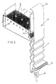
- the structure of a zigzag sifter module with the associated spray nozzle group 5 and the associated inflow zone 2 can be seen in detail from FIG.
- the module shown in FIG. 2 can therefore be regarded as an independent unit.
- such units are assembled into a large fluidized bed granulating system with a rectangular cross section.
- the granulator cross-section specified in terms of the desired throughput can be covered without gaps without difficulty.
- the module shown in FIG. 2 is dimensioned such that the width B of the fluidized bed granulator is equal to the length l of a zigzag sifter channel or the associated inflow zone and the length L of the fluidized bed granulator is an integer multiple of the width b of the zig -Zack sifter channel is.
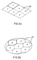
- FIGS. 4 to 5 An alternative embodiment of the invention can be implemented with the single-nozzle module according to FIGS. 4 to 5.
- the module is formed here by a single spray nozzle 5, which is arranged in the center of a rectangular or hexagonal inflow base element 16, an annular zigzag sifter 17 and a return shaft 18, which is placed at the connection point of the inflow base 16 and concentrically surrounds the spray nozzle 5.
- the annular zigzag classifier channel 19 here also encloses the feed lines 20 for the two-substance spray nozzle 5 (gas and liquid starting material). Similar to the embodiment according to FIGS. 1 and 2, the granulate to be sifted is sucked in through an annular gap 21 (underflow weir) between the return shaft 18 and the sifter module 17.
- the suction generated by the two-substance nozzle 5 is supported by the collar-shaped cross-sectional constriction 22 at the outlet of the return shaft 18.
- the undersize particles are conveyed directly into the spray jet and are wetted there with the granulating liquid. This in turn improves the growth conditions for the undersize.
- the wetted particles then fall out of the spray jet counter to the fluidizing air flow 23 downward, the applied liquid shell solidifying on the particle and in this way producing a larger granule size.
- the particles are again fed to the annular zigzag classifier module 17.
- the same physical criteria are decisive as in the embodiment according to FIGS.
- filter elements for exhaust air purification can be installed in each case via a zigzag sifter module according to FIG. 4.
Landscapes
- Chemical & Material Sciences (AREA)
- Organic Chemistry (AREA)
- Chemical Kinetics & Catalysis (AREA)
- Glanulating (AREA)
- Devices And Processes Conducted In The Presence Of Fluids And Solid Particles (AREA)
Applications Claiming Priority (2)
| Application Number | Priority Date | Filing Date | Title |
|---|---|---|---|
| DE3808277 | 1988-03-12 | ||
| DE3808277A DE3808277A1 (de) | 1988-03-12 | 1988-03-12 | Verfahren und vorrichtung zur wirbelschichtspruehgranulation |
Publications (3)
| Publication Number | Publication Date |
|---|---|
| EP0332929A1 EP0332929A1 (de) | 1989-09-20 |
| EP0332929B1 EP0332929B1 (de) | 1991-05-08 |
| EP0332929B2 true EP0332929B2 (de) | 1995-08-02 |
Family
ID=6349560
Family Applications (1)
| Application Number | Title | Priority Date | Filing Date |
|---|---|---|---|
| EP89103542A Expired - Lifetime EP0332929B2 (de) | 1988-03-12 | 1989-03-01 | Verfahren und Vorrichtung zur Wirbelschichtsprühgranulation |
Country Status (3)
| Country | Link |
|---|---|
| EP (1) | EP0332929B2 (ja) |
| JP (1) | JP2811578B2 (ja) |
| DE (2) | DE3808277A1 (ja) |
Families Citing this family (31)
| Publication number | Priority date | Publication date | Assignee | Title |
|---|---|---|---|---|
| US5149643A (en) * | 1990-10-05 | 1992-09-22 | Haarmann & Beimer | Method for the production of granular citric acid and salts thereof |
| US5104799A (en) * | 1990-10-05 | 1992-04-14 | Haarmann & Reimer | Method for the production of granular citric acid and salts thereof |
| US5045459A (en) * | 1990-10-05 | 1991-09-03 | Haarmann & Reimer Corp. | Method for the production of granular citric acid |
| DE4200821A1 (de) * | 1992-01-15 | 1993-07-22 | Bayer Ag | Geschmacksmaskierte pharmazeutische mittel |
| DE4304405A1 (de) * | 1993-02-15 | 1994-08-18 | Bayer Ag | Verfahren zur kontinuierlichen Wirbelschichtagglomeration |
| US5560896A (en) * | 1993-08-31 | 1996-10-01 | Degussa Aktiengesellschaft | Method for producing granulated sodium percarbonate |
| DE19514187C1 (de) * | 1995-04-21 | 1996-05-15 | Degussa | Verfahren und Vorrichtung zur Herstellung von Granulaten durch Wirbelschicht-Sprühgranulation |
| DE19602525A1 (de) * | 1996-01-25 | 1997-08-07 | Starck H C Gmbh Co Kg | Sphärische Keramikformkörper, Verfahren zu ihrer Herstellung sowie deren Verwendung |
| DE19629690C2 (de) * | 1996-07-23 | 1999-08-05 | Korund Laufenburg Gmbh | Verfahren zur Herstellung gesinterter alpha-AL¶2¶0¶3¶-Körper sowie deren Verwendung |
| DE19700029B4 (de) * | 1997-01-02 | 2006-03-09 | Glatt Ingenieurtechnik Gmbh | Wirbelschichtapparat |
| EP0870537B1 (de) * | 1997-04-09 | 2004-10-06 | Symrise GmbH & Co. KG | Verfahren zur Herstellung alkoholhaltiger Granulate |
| DE19744708A1 (de) * | 1997-10-10 | 1999-04-15 | Bayer Ag | Verfahren und Vorrichtung zum Ausschleusen von Kautschuk aus der Gasphasenpolymerisation |
| DE19808439C1 (de) * | 1998-02-27 | 1999-09-30 | Degussa | Wirbelschichtreaktor und seine Verwendung |
| NO312712B1 (no) * | 1999-12-15 | 2002-06-24 | Norsk Hydro As | En sorterende fluid bed granulator samt fremgangsmåte for fluid bed granulering |
| DE10130334A1 (de) * | 2001-06-26 | 2003-01-02 | Glatt Ingtech Gmbh | Verfahren zum Coating von körnigen und pulverförmigen Materialien |
| DE10146778B4 (de) * | 2001-09-22 | 2009-02-05 | Glatt Ingenieurtechnik Gmbh | Verfahren und Wirbelschichtanlage zur Herstellung von kompakten Feststoffpartikeln |
| DE10326231B4 (de) * | 2003-06-11 | 2016-04-07 | Glatt Ingenieurtechnik Gmbh | Verfahren zur Herstellung von Enzym-Granulaten |
| DE10357827A1 (de) * | 2003-12-09 | 2005-07-14 | Glatt Ingenieurtechnik Gmbh | Verfahren zur Herstellung von Enzym-Granulaten und erhältliche Enzym-Granulate |
| AU2004245660B2 (en) | 2003-06-11 | 2009-06-11 | Glatt Ingenieurtechnik Gmbh | Method for production of enzyme granules and enzyme granules produced thus |
| DE102004022310B4 (de) * | 2004-05-04 | 2010-01-07 | Daimler Ag | Brennstoffzellensystem mit einem Feuchtigkeitsaustauschmodul mit einem Bündel von für Feuchtigkeit durchlässigen Hohlfasermembranen |
| DE102005019444B4 (de) * | 2005-04-21 | 2008-02-28 | Glatt Gmbh | Sprühdüse für eine Wirbelschichteinrichtung |
| DE102006004833A1 (de) * | 2006-02-02 | 2007-08-16 | Holger Mannweiler | Verfahren zum Trocknen von Saft |
| EP1958520A3 (de) | 2007-02-09 | 2013-04-03 | Symrise AG | Wirbelschichtgranulate mit hohem Fruchtanteil |
| JP4455643B2 (ja) | 2007-10-30 | 2010-04-21 | 東洋エンジニアリング株式会社 | 造粒装置及びそれを用いる造粒方法 |
| US7722722B2 (en) * | 2007-11-16 | 2010-05-25 | Brunob Ii B.V. | Continuous fluid bed reactor |
| JP5102851B2 (ja) * | 2010-02-04 | 2012-12-19 | 東洋エンジニアリング株式会社 | 造粒装置及びそれを用いる造粒方法 |
| EP2993221B1 (de) | 2014-09-08 | 2019-01-09 | Symrise AG | Verkapselte Duftstoffmischungen |
| EP3097962B1 (de) * | 2015-05-29 | 2020-05-13 | Symrise AG | Vorrichtung zur herstellung von sprühgetrockneten agglomeraten |
| EP3117720B1 (de) * | 2015-05-29 | 2019-02-20 | Symrise AG | Grosse agglomeratpartikel |
| CN110551899A (zh) * | 2019-09-25 | 2019-12-10 | 骆驼集团(安徽)再生资源有限公司 | 一种高效节能再生铅冶炼工艺 |
| CN112620085B (zh) * | 2020-12-29 | 2021-12-21 | 中铁二十四局集团西南建设有限公司 | 一种建筑工程循环筛沙装置 |
Family Cites Families (2)
| Publication number | Priority date | Publication date | Assignee | Title |
|---|---|---|---|---|
| CH584567A5 (en) * | 1972-06-06 | 1977-02-15 | Ciba Geigy Ag | Granular material prodn. in fluidised bed - with 70 per cent. of particles between 0.15 and 2 mm. |
| JPH0757311B2 (ja) * | 1986-07-09 | 1995-06-21 | 株式会社大川原製作所 | 連続造粒装置 |
-
1988
- 1988-03-12 DE DE3808277A patent/DE3808277A1/de not_active Withdrawn
-
1989
- 1989-03-01 DE DE8989103542T patent/DE58900108D1/de not_active Expired - Lifetime
- 1989-03-01 EP EP89103542A patent/EP0332929B2/de not_active Expired - Lifetime
- 1989-03-10 JP JP1056573A patent/JP2811578B2/ja not_active Expired - Lifetime
Also Published As
| Publication number | Publication date |
|---|---|
| DE3808277A1 (de) | 1989-09-21 |
| JPH01274832A (ja) | 1989-11-02 |
| EP0332929B1 (de) | 1991-05-08 |
| EP0332929A1 (de) | 1989-09-20 |
| JP2811578B2 (ja) | 1998-10-15 |
| DE58900108D1 (de) | 1991-06-13 |
Similar Documents
| Publication | Publication Date | Title |
|---|---|---|
| EP0332929B2 (de) | Verfahren und Vorrichtung zur Wirbelschichtsprühgranulation | |
| US5213820A (en) | Process and device for fluidized bed spray granulation | |
| EP0318054B1 (de) | Verfahren und Vorrichtung zum Auslesen von schweren Beimengungen aus Korngut | |
| DE3117892A1 (de) | Strahlschicht-granulator | |
| DE2202311C2 (de) | Anlage zur Wiedergewinnung von Sand aus dem beim Abstrahlen von kunstharzgebundenen Formen anfallenden Gemisch | |
| EP2159526A2 (de) | Bearbeitungsanlage für Schüttgut | |
| DE2313847A1 (de) | Verfahren und vorrichtung zur abtrennung von sand von pflanzlichen materialien, insbesondere tabak | |
| EP0593955B1 (de) | Vorrichtung und Verfahren zum Reinigen eines im wesentlichen in Granulatform vorliegenden Korngemenges | |
| EP0260506A2 (de) | Kühlvorrichtung für Kunststoffgranulat | |
| EP2352579B1 (de) | Verfahren und vorrichtung zur behandlung von feinkörnigem material in einer strahlschicht | |
| DE3203209C1 (de) | Umlenksichter | |
| DE3626053C2 (ja) | ||
| DE2551457C2 (de) | Vorrichtung zum Trennen von Stäuben in Grobgut und Feingut im Zentrifugalfeld | |
| DE1901020A1 (de) | Hydraulisches Aufstromklassiergeraet | |
| EP1407814B1 (de) | Verfahren und Vorrichtung mit Wirbelschichtanlage zur Herstellung von Granulaten | |
| DE3310709C2 (ja) | ||
| DE10146778A1 (de) | Verfahren und Wirbelschichtanlage zur Herstellung von kompakten Feststoffpartikeln | |
| DE19957993B4 (de) | Kegelsichter und Verfahren zum Sichten von eingeschränkt oder nicht rieselfähigem Schüttgut und Halterungsstrebe | |
| DE2710543C2 (ja) | ||
| EP0385241A1 (de) | Siebmaschine | |
| DE2641068A1 (de) | Steigrohrwindsichter zur entsandung von holzspaenen | |
| EP0758931B1 (de) | Umlenk-gegenstrom-sichter | |
| CH637845A5 (de) | Verfahren und vorrichtung zur intermittierenden, regenerierenden reinigung eines filterbettes. | |
| DE19915122A1 (de) | Steigrohrsichter für die Wirbelschichtgranulation | |
| DE899931C (de) | Verfahren und Vorrichtung zur Klassierung von Gemischen nach Fallgeschwindigkeit im aufsteigenden Fluessigkeitsstrom |
Legal Events
| Date | Code | Title | Description |
|---|---|---|---|
| PUAI | Public reference made under article 153(3) epc to a published international application that has entered the european phase |
Free format text: ORIGINAL CODE: 0009012 |
|
| 17P | Request for examination filed |
Effective date: 19890301 |
|
| AK | Designated contracting states |
Kind code of ref document: A1 Designated state(s): BE CH DE FR GB IT LI NL |
|
| 17Q | First examination report despatched |
Effective date: 19900731 |
|
| GRAA | (expected) grant |
Free format text: ORIGINAL CODE: 0009210 |
|
| AK | Designated contracting states |
Kind code of ref document: B1 Designated state(s): BE CH DE FR GB IT LI NL |
|
| ITF | It: translation for a ep patent filed |
Owner name: ING. C. GREGORJ S.P.A. |
|
| REF | Corresponds to: |
Ref document number: 58900108 Country of ref document: DE Date of ref document: 19910613 |
|
| GBT | Gb: translation of ep patent filed (gb section 77(6)(a)/1977) | ||
| ET | Fr: translation filed | ||
| PLBI | Opposition filed |
Free format text: ORIGINAL CODE: 0009260 |
|
| 26 | Opposition filed |
Opponent name: HENKEL KOMMANDITGESELLSCHAFT AUF AKTIEN Effective date: 19920124 |
|
| NLR1 | Nl: opposition has been filed with the epo |
Opponent name: HENKEL KOMMANDITGESELLSCHAFT AUF AKTIEN |
|
| PUAH | Patent maintained in amended form |
Free format text: ORIGINAL CODE: 0009272 |
|
| STAA | Information on the status of an ep patent application or granted ep patent |
Free format text: STATUS: PATENT MAINTAINED AS AMENDED |
|
| 27A | Patent maintained in amended form |
Effective date: 19950802 |
|
| AK | Designated contracting states |
Kind code of ref document: B2 Designated state(s): BE CH DE FR GB IT LI NL |
|
| GBTA | Gb: translation of amended ep patent filed (gb section 77(6)(b)/1977) |
Effective date: 19950802 |
|
| REG | Reference to a national code |
Ref country code: CH Ref legal event code: AEN |
|
| ET3 | Fr: translation filed ** decision concerning opposition | ||
| ITF | It: translation for a ep patent filed |
Owner name: ING. C. GREGORJ S.P.A. |
|
| NLR2 | Nl: decision of opposition | ||
| NLR3 | Nl: receipt of modified translations in the netherlands language after an opposition procedure | ||
| REG | Reference to a national code |
Ref country code: GB Ref legal event code: IF02 |
|
| PGFP | Annual fee paid to national office [announced via postgrant information from national office to epo] |
Ref country code: DE Payment date: 20040527 Year of fee payment: 16 |
|
| PG25 | Lapsed in a contracting state [announced via postgrant information from national office to epo] |
Ref country code: DE Free format text: LAPSE BECAUSE OF NON-PAYMENT OF DUE FEES Effective date: 20051001 |
|
| REG | Reference to a national code |
Ref country code: CH Ref legal event code: PFA Owner name: BAYER AKTIENGESELLSCHAFT Free format text: BAYER AKTIENGESELLSCHAFT# #D-51368 LEVERKUSEN (DE) -TRANSFER TO- BAYER AKTIENGESELLSCHAFT# #D-51368 LEVERKUSEN (DE) |
|
| PGFP | Annual fee paid to national office [announced via postgrant information from national office to epo] |
Ref country code: CH Payment date: 20080228 Year of fee payment: 20 |
|
| PGFP | Annual fee paid to national office [announced via postgrant information from national office to epo] |
Ref country code: GB Payment date: 20080227 Year of fee payment: 20 Ref country code: NL Payment date: 20080229 Year of fee payment: 20 |
|
| PGFP | Annual fee paid to national office [announced via postgrant information from national office to epo] |
Ref country code: FR Payment date: 20080311 Year of fee payment: 20 |
|
| PGFP | Annual fee paid to national office [announced via postgrant information from national office to epo] |
Ref country code: BE Payment date: 20080522 Year of fee payment: 20 |
|
| PGFP | Annual fee paid to national office [announced via postgrant information from national office to epo] |
Ref country code: IT Payment date: 20080327 Year of fee payment: 19 |
|
| REG | Reference to a national code |
Ref country code: CH Ref legal event code: PL |
|
| REG | Reference to a national code |
Ref country code: GB Ref legal event code: PE20 Expiry date: 20090228 |
|
| BE20 | Be: patent expired |
Owner name: *BAYER A.G. Effective date: 20090301 |
|
| NLV7 | Nl: ceased due to reaching the maximum lifetime of a patent |
Effective date: 20090301 |
|
| PG25 | Lapsed in a contracting state [announced via postgrant information from national office to epo] |
Ref country code: NL Free format text: LAPSE BECAUSE OF EXPIRATION OF PROTECTION Effective date: 20090301 |
|
| PG25 | Lapsed in a contracting state [announced via postgrant information from national office to epo] |
Ref country code: GB Free format text: LAPSE BECAUSE OF EXPIRATION OF PROTECTION Effective date: 20090228 |
|
| PG25 | Lapsed in a contracting state [announced via postgrant information from national office to epo] |
Ref country code: IT Free format text: LAPSE BECAUSE OF NON-PAYMENT OF DUE FEES Effective date: 20080301 |