EP0332602B1 - Procédé pour le revêtement d'éléments en plastique expansé - Google Patents
Procédé pour le revêtement d'éléments en plastique expansé Download PDFInfo
- Publication number
- EP0332602B1 EP0332602B1 EP89870037A EP89870037A EP0332602B1 EP 0332602 B1 EP0332602 B1 EP 0332602B1 EP 89870037 A EP89870037 A EP 89870037A EP 89870037 A EP89870037 A EP 89870037A EP 0332602 B1 EP0332602 B1 EP 0332602B1
- Authority
- EP
- European Patent Office
- Prior art keywords
- coated
- expanded
- procedure
- coating
- sheets
- Prior art date
- Legal status (The legal status is an assumption and is not a legal conclusion. Google has not performed a legal analysis and makes no representation as to the accuracy of the status listed.)
- Expired - Lifetime
Links
Images


Classifications
-
- B—PERFORMING OPERATIONS; TRANSPORTING
- B23—MACHINE TOOLS; METAL-WORKING NOT OTHERWISE PROVIDED FOR
- B23D—PLANING; SLOTTING; SHEARING; BROACHING; SAWING; FILING; SCRAPING; LIKE OPERATIONS FOR WORKING METAL BY REMOVING MATERIAL, NOT OTHERWISE PROVIDED FOR
- B23D49/00—Machines or devices for sawing with straight reciprocating saw blades, e.g. hacksaws
- B23D49/003—Machines or devices for sawing with straight reciprocating saw blades, e.g. hacksaws having a plurality of saw blades or saw blades having plural cutting zones
- B23D49/005—Machines or devices for sawing with straight reciprocating saw blades, e.g. hacksaws having a plurality of saw blades or saw blades having plural cutting zones with opposed saw blades
-
- B—PERFORMING OPERATIONS; TRANSPORTING
- B32—LAYERED PRODUCTS
- B32B—LAYERED PRODUCTS, i.e. PRODUCTS BUILT-UP OF STRATA OF FLAT OR NON-FLAT, e.g. CELLULAR OR HONEYCOMB, FORM
- B32B5/00—Layered products characterised by the non- homogeneity or physical structure, i.e. comprising a fibrous, filamentary, particulate or foam layer; Layered products characterised by having a layer differing constitutionally or physically in different parts
- B32B5/18—Layered products characterised by the non- homogeneity or physical structure, i.e. comprising a fibrous, filamentary, particulate or foam layer; Layered products characterised by having a layer differing constitutionally or physically in different parts characterised by features of a layer of foamed material
-
- B—PERFORMING OPERATIONS; TRANSPORTING
- B26—HAND CUTTING TOOLS; CUTTING; SEVERING
- B26D—CUTTING; DETAILS COMMON TO MACHINES FOR PERFORATING, PUNCHING, CUTTING-OUT, STAMPING-OUT OR SEVERING
- B26D1/00—Cutting through work characterised by the nature or movement of the cutting member or particular materials not otherwise provided for; Apparatus or machines therefor; Cutting members therefor
- B26D1/56—Cutting through work characterised by the nature or movement of the cutting member or particular materials not otherwise provided for; Apparatus or machines therefor; Cutting members therefor involving a cutting member which travels with the work otherwise than in the direction of the cut, i.e. flying cutter
- B26D1/60—Cutting through work characterised by the nature or movement of the cutting member or particular materials not otherwise provided for; Apparatus or machines therefor; Cutting members therefor involving a cutting member which travels with the work otherwise than in the direction of the cut, i.e. flying cutter and is mounted on a movable carriage
-
- B—PERFORMING OPERATIONS; TRANSPORTING
- B29—WORKING OF PLASTICS; WORKING OF SUBSTANCES IN A PLASTIC STATE IN GENERAL
- B29C—SHAPING OR JOINING OF PLASTICS; SHAPING OF MATERIAL IN A PLASTIC STATE, NOT OTHERWISE PROVIDED FOR; AFTER-TREATMENT OF THE SHAPED PRODUCTS, e.g. REPAIRING
- B29C63/00—Lining or sheathing, i.e. applying preformed layers or sheathings of plastics; Apparatus therefor
- B29C63/02—Lining or sheathing, i.e. applying preformed layers or sheathings of plastics; Apparatus therefor using sheet or web-like material
- B29C63/04—Lining or sheathing, i.e. applying preformed layers or sheathings of plastics; Apparatus therefor using sheet or web-like material by folding, winding, bending or the like
-
- B—PERFORMING OPERATIONS; TRANSPORTING
- B32—LAYERED PRODUCTS
- B32B—LAYERED PRODUCTS, i.e. PRODUCTS BUILT-UP OF STRATA OF FLAT OR NON-FLAT, e.g. CELLULAR OR HONEYCOMB, FORM
- B32B27/00—Layered products comprising a layer of synthetic resin
- B32B27/06—Layered products comprising a layer of synthetic resin as the main or only constituent of a layer, which is next to another layer of the same or of a different material
- B32B27/065—Layered products comprising a layer of synthetic resin as the main or only constituent of a layer, which is next to another layer of the same or of a different material of foam
-
- B—PERFORMING OPERATIONS; TRANSPORTING
- B32—LAYERED PRODUCTS
- B32B—LAYERED PRODUCTS, i.e. PRODUCTS BUILT-UP OF STRATA OF FLAT OR NON-FLAT, e.g. CELLULAR OR HONEYCOMB, FORM
- B32B27/00—Layered products comprising a layer of synthetic resin
- B32B27/06—Layered products comprising a layer of synthetic resin as the main or only constituent of a layer, which is next to another layer of the same or of a different material
- B32B27/08—Layered products comprising a layer of synthetic resin as the main or only constituent of a layer, which is next to another layer of the same or of a different material of synthetic resin
-
- B—PERFORMING OPERATIONS; TRANSPORTING
- B32—LAYERED PRODUCTS
- B32B—LAYERED PRODUCTS, i.e. PRODUCTS BUILT-UP OF STRATA OF FLAT OR NON-FLAT, e.g. CELLULAR OR HONEYCOMB, FORM
- B32B37/00—Methods or apparatus for laminating, e.g. by curing or by ultrasonic bonding
- B32B37/04—Methods or apparatus for laminating, e.g. by curing or by ultrasonic bonding characterised by the partial melting of at least one layer
-
- B—PERFORMING OPERATIONS; TRANSPORTING
- B32—LAYERED PRODUCTS
- B32B—LAYERED PRODUCTS, i.e. PRODUCTS BUILT-UP OF STRATA OF FLAT OR NON-FLAT, e.g. CELLULAR OR HONEYCOMB, FORM
- B32B37/00—Methods or apparatus for laminating, e.g. by curing or by ultrasonic bonding
- B32B37/14—Methods or apparatus for laminating, e.g. by curing or by ultrasonic bonding characterised by the properties of the layers
- B32B37/16—Methods or apparatus for laminating, e.g. by curing or by ultrasonic bonding characterised by the properties of the layers with all layers existing as coherent layers before laminating
- B32B37/18—Methods or apparatus for laminating, e.g. by curing or by ultrasonic bonding characterised by the properties of the layers with all layers existing as coherent layers before laminating involving the assembly of discrete sheets or panels only
-
- B—PERFORMING OPERATIONS; TRANSPORTING
- B32—LAYERED PRODUCTS
- B32B—LAYERED PRODUCTS, i.e. PRODUCTS BUILT-UP OF STRATA OF FLAT OR NON-FLAT, e.g. CELLULAR OR HONEYCOMB, FORM
- B32B38/00—Ancillary operations in connection with laminating processes
-
- B—PERFORMING OPERATIONS; TRANSPORTING
- B32—LAYERED PRODUCTS
- B32B—LAYERED PRODUCTS, i.e. PRODUCTS BUILT-UP OF STRATA OF FLAT OR NON-FLAT, e.g. CELLULAR OR HONEYCOMB, FORM
- B32B38/00—Ancillary operations in connection with laminating processes
- B32B38/18—Handling of layers or the laminate
-
- B—PERFORMING OPERATIONS; TRANSPORTING
- B29—WORKING OF PLASTICS; WORKING OF SUBSTANCES IN A PLASTIC STATE IN GENERAL
- B29C—SHAPING OR JOINING OF PLASTICS; SHAPING OF MATERIAL IN A PLASTIC STATE, NOT OTHERWISE PROVIDED FOR; AFTER-TREATMENT OF THE SHAPED PRODUCTS, e.g. REPAIRING
- B29C2793/00—Shaping techniques involving a cutting or machining operation
- B29C2793/009—Shaping techniques involving a cutting or machining operation after shaping
-
- B—PERFORMING OPERATIONS; TRANSPORTING
- B32—LAYERED PRODUCTS
- B32B—LAYERED PRODUCTS, i.e. PRODUCTS BUILT-UP OF STRATA OF FLAT OR NON-FLAT, e.g. CELLULAR OR HONEYCOMB, FORM
- B32B2266/00—Composition of foam
- B32B2266/02—Organic
- B32B2266/0214—Materials belonging to B32B27/00
- B32B2266/0221—Vinyl resin
- B32B2266/0228—Aromatic vinyl resin, e.g. styrenic (co)polymers
-
- B—PERFORMING OPERATIONS; TRANSPORTING
- B32—LAYERED PRODUCTS
- B32B—LAYERED PRODUCTS, i.e. PRODUCTS BUILT-UP OF STRATA OF FLAT OR NON-FLAT, e.g. CELLULAR OR HONEYCOMB, FORM
- B32B2266/00—Composition of foam
- B32B2266/02—Organic
- B32B2266/0214—Materials belonging to B32B27/00
- B32B2266/025—Polyolefin
Definitions
- the present invention concerns a procedure for coating elements consisting in expanded plastic, also named foam plastic.
- expanded plastic such as for instance polystyrene, polyethylene and other similar materials, are obtained in various applications. Examples of it can be found in great numbers in the insulation technology, the packaging industry and in the decoration techniques.
- Present invention aims at a procedure for coating elements in expanded plastic, in such way that the produced products do not have aforementioned disadvantages any more.
- a tougher plastic layer is applied to the surface of the elements in expanded plastic and in such a manner that, between the coating material layer and the element to be coated, a solid, practically unbreakable, connection is created.
- the products obtained according to the invention thus also have the advantage that they are sturdier than those products which are not provided with aforementioned coating.
- the strength reveals itself primarily by a substantial surface hardness, an increased breaking strength and an improved portative power. This, in turn, shows the advantage that the obtained products enjoy a longer lifespan.
- Present invention also aims at a procedure in which the application of the layer of coating material on the element two be coated occurs in such way that the constantly appearing grain shaped structure of the expanded plastic does not or seldom show in the applied layer of coating material, due to which latter remains smooth, with the advantage that the obtained products are easier to be wet cleaned and that dirt does not adhere to such an extent to the coating's surface.
- the procedure according to the invention has, moreover, the advantage that the elements in expanded plastic can be provided with a coating of any colour.
- the present invention provides in a process for coating elements in expanded materials, providing a coating which is firmly attached to said elements.
- the invention concerns a procedure for coating an expanded plastic element comprising the steps of heating a coating layer consisting of the same but non expanded material as said plastic element; pressing the heated layer to the expanded plastic element in such a way that the cooperating surfaces melt together forming a composite element; and cooling said composite element.
- the same basic material is chosen for the expanded element and the non expanded layer offers the advantage that the melting points of the element to be coated and of the coating layer are the same and consequently an optimal melting effect can be obtained.
- the coating material By heating the coating material at its contact side to the melting point and bringing it in contact with the expanded element, the latter at Its surface also reaches a temperature equal to the melting point, and consequently both materials, from the coating and from the element to be coated, mix with each other at their surface and become unified in an optimal manner.
- present invention aims herewith at the coating of stratified elements, such as sheets and similar.
- An additional aims consists in that the coating of such sheets can be achieved efficiently by means of a continuous process.
- the pressing of a layer of coating material against the element to be coated occurs by bringing the heated layer by means of a continuously progressing movement in contact with one or more elements in expanded plastic to be coated.
- the heated layer is being rolled on these elements, which offers the special advantage that finished products with a very smooth surface are obtained in which the grain shaped structure of the expanded material on its exterior surface becomes virtually invisible.
- the layer of coating material is herewith being taken from a reel, while the expanded elements consist in sheets which are being supplied in sequence.
- the sheets are being coated on both sides by applying aforementioned method, which offers the advantage that the finished product, according to present invention as well, can be separated in any length, regardless of the locations in which the used sheets of expanded material connect with one another.
- the applied layer of coating material is being chosen wider than the elements, respectively sheets, to be coated, and the coating material is being folded over the edges of the sheets to be coated while it is still hot, in such way that the finished product obtains a finished appearance as well as shockproof edges.
- wooden strips are being provided at the edges of the sheets to be coated during aforementioned continuous process, in such way that the layer of coating material is being bent over these and that strips are affixed.
- the layer of coating material will preferably be heated until softening, whereupon it immediately is pressed against the element, for instance a sheet, to be coated.
- the element for instance a sheet
- the layer of coating material will preferably be heated until softening, whereupon it immediately is pressed against the element, for instance a sheet, to be coated.
- an expanded plastic within the types of insulation material, more particularly materials such as expanded polystyrene, expanded polyethylene or similar expanded materials.
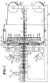
- the device for carrying out the procedure of the invention mainly consists in a track 1, preferably a roller track, for the supply of elements in expanded plastic, primarily sheets 2 ; means 3 to supply one or more layers of coating material, respectively 4 and 5 ; heating means 6 for the respective heating up of aforementioned layers 4 and 5 ; rollers 7 to press the heated layer of coating material 4-5 against sheets 2 by rolling and driving means which will be further described hereafter.
- a device is shown in figure 1 in which, at both sides of sheet 2, a layer of coating material is applied; it is obvious that the procedure can be carried out with one layer 4 or 5 only, in such way that a variant of the device according to the invention can also exclusively consist in the upper or lower part of the machine represented in figure 1.
- the sheets supply track 1 is preferably equipped with guides 8 adjustable in width.
- the means 3 for the supply of layers 4-5 mainly consist in reel supports 9 and 10 on which reels 11 and 12 with the concerned coating material can be placed, a number of folding cylinders 13 and driven guiding means 14.
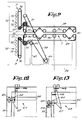
- Each of these guiding means 14 consists, as shown in figures 1 through 4, mainly in a continuous chain 15 which is guided over two sprocket wheels 16 and 17, in which sprocket wheel 17 is mounted on a driven shaft 18, and free rotating sprocket wheels 19 which are being pushed towards the free parts of the chain 15 by means of tensioning means 20.
- Such guiding means 14 are placed at both edges of layers 4 and 5 in such way that the layers are guided between chain 5 and the free rotating sprocket wheels 19, be clamped between them and transported along the heating means 6 by the chain's 15 movement.
- the sprocket wheels 19 press the layers 4-5 locally in the apertures of the chain links in the chains 15.
- the tensioning means 20 mainly consist in universal joints 21 which, on the one hand, are installed on a fixed frame section 22 and which, on the other hand, carry a movable frame section 23 on which the free rotating sprocket wheels 19 are installed, as well as in draw springs 24 which provide the required stretching force.
- the complete device is preferably provided with width adjusting means in such way that sheets and coating materials of different widths can be processed.
- the aforementioned frame sections 22 and 23 are slidable and adjustable in a support 25 which is linked with the machine frame 26 as such.
- the sprocket wheels 16 and 17 are also freely sliding along their shafts 18 and 27 and are carried along by the movement of the frame section 23 by means of a fork 28, as shown in figure 4.
- Aforementioned driving means for the transport of the formed finished product is factually being formed by a number of aforementioned rollers 7, more particularly these rolls which, as shown in figures 5 and 6, are power driven, for instance by means of a circular chain 29 which drives said rollers 7 via sprocket wheels 30 arid which in turn is being driven by means of a driven shaft 31. It is evident that a similar construction is provided for on the lower as well as on the upper parts.
- the first rollers 7, between which the sheets 2 and layers 4 and 5 are guided, do not only act as rollers but as folding cylinder as well.
- a folding ring or folding flange 32 is provided on one of the following cylinder pairs, preferably at both edges of each roller in order to fold the layers of coating material 4-5 over the edges of the sheets 2, as shown in figure 7, obviously when required for the finished product.
- guides, such as wooden strips 33, are preferably provided for, with which the folded parts 34 are being pressed for some time contacting the edges of sheets 2, until the layer of coating material 4, respectively 5, has sufficiently cooled down and is firmly attached to the base sheet 2. The excess material of parts 34 is cut away later on.
- the upper and lower part of the device are movable with respect to one another by means of lifting devices 35, for instance formed by a screw spindle 36, provided with a crank 37 in which, on the one hand, the lower extremity of the screw spindle 36 rests freely on the frame of the lower part of the device and, on the other hand, in which this screw spindle 36 passes through a threaded mounting 38 at the upper part of the device.
- lifting devices 35 for instance formed by a screw spindle 36, provided with a crank 37 in which, on the one hand, the lower extremity of the screw spindle 36 rests freely on the frame of the lower part of the device and, on the other hand, in which this screw spindle 36 passes through a threaded mounting 38 at the upper part of the device.
- aforementioned driven shafts 18 and 31, as well as chains 15 and 29, are drivers by means of a chain 39 which in turn is driven by an electric motor 40.
- a gear 42 movable along a guide 41 allows for chain 39 to be adjusted with respect to the adjustment of the lifting devices 35.
- the heating means 6 preferably consist in multiple, broadwise arranged rows of infrared lamps 43 situated next to one another, which are connected individually or in groups with adjusting devices 44 for the admission of electric power, in such way that the desired temperatures, in layers 4 and 5 can be maintained. It is evident that a smaller loss of heat occurs at the centre of the embodiment, where consequently less power has to be fed to the interior rows 43 than to the outer rows.
- a reflector 45 is preferably located, while a removable protection sheet 46 can be provided for it.
- air 47 is preferably blown in, towards the bottom, in order to achieve an uniform spread of heat. This could be for instance achieved by means of a perforated pipe 48 which is connected with a compressor 49.
- the first rollers 7 are preferably cooled by means of blowing devices 50, such as fans, in order to avoid that they would reach a high temperature after some time, through which layers 4 and 5 would stick to these rollers 7.
- blowing devices 50 such as fans
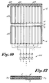
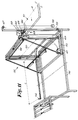
- the coating device is preferably equipped, at the side where the formed finished product 51 leaves, as shown in figure 11, with an almost automatically operating cutting device 52, with which the finished product 51, regardless of the locations 53 where the sheets 2 join, can be separated in desired lengths L.
- the cutting device 52 mainly consists in a frame 55, rolling over guides 54, which by means of an adjustable stop 56 and by means of the arriving product 51 can be moved in the direction of movement of latter and moving it in opposite direction by means of a weight 58 suspended to a pulley 57, which always forces the frame 55 into one direction by means of a cable 59, opposite to the movement of the product 51.
- the factual cutting means consist in a filament 60, for instance connected with a battery 61, in which this filament 60 is installed in a frame 62, moving up and down, in the frame 55.
- the frame 62 In the initial position according to figure 11, the frame 62 is maintained in its highest position by means of stops 63 consisting in a support 64 connected with the frame 62 which rests by means of a small roller 65 or similar on a fixed stop 66.
- the cutting device's 52 operation can be easily deduced from the drawing and consists in that the product 51 slides through the frame 55 until it meets the stop 56. From that moment on, frame 55 is carried along by the movement of the product 51 and the support 64 is released from the stop 66, in which frame 62 with the filament 60 falls onto the finished product 51 which melts, while frame 55 and product 51 continue their movement.
- a sheet with a length L is produced which then has to be removed.
- the operator pulls the frame 55 a bit forward and pushes frame 62 with the filament 60 back up.
- Frame 62 will then hook onto an elastically movable stop 67, as shown in figure 12, in which, for instance, aforementioned support 64 hooks on.
- the frame 55 When the frame 55 is then released, it will roll back under the influence of the weight 58 to its initial position, in which the movable stop 67 is being pushed aside by means of a permanent stop 68, in such way as shown in figure 13, in which the support 64 together with the roller 65 will drop onto aforementioned stop 66.
- the dropping movement of the frame 62 can be limited by providing for a counterweight 69, in which the filament will land on the product 51 to be cut in a smooth downward movement.
- the heating means 6 can, as well as the guiding means 14, not shown in this drawing, be located in such way that they provide for an inclined movement of layers 4 and/or 5, in which latter are being bent less sharply and substantially thick layers 4 and 5 can be applied, which in this case can be supplied either from reels 9 and 10 or in the form of sheets.
- Figure 15 represents the product discussed in the introduction, in which at both edges of the sheets 2 wooden strips 70 are added, which in the aforementioned continuous process can be supplied to the machine together with sheets 2. Strips 70 are kept in location because the coating layers 4 and 5 are bent around these strips. It is evident that, in this case, automatic sawing machines 71 are placed at the discharging end of the embodiment, in such way as shown in figure 16. These sawing machines 71 will then saw off strips 70 whereupon the plastic parts can be cut afterward by means of, for instance, aforementioned filament 60.
Landscapes
- Engineering & Computer Science (AREA)
- Mechanical Engineering (AREA)
- Life Sciences & Earth Sciences (AREA)
- Forests & Forestry (AREA)
- Manufacturing & Machinery (AREA)
- Laminated Bodies (AREA)
- Application Of Or Painting With Fluid Materials (AREA)
- Manufacture Of Porous Articles, And Recovery And Treatment Of Waste Products (AREA)
- Shaping Of Tube Ends By Bending Or Straightening (AREA)
Claims (9)
- Procédé pour recouvrir un élément en plastique expansé, comprenant les étapes consistant à chauffer une couche de revêtement (4, 5) constituée de la même matière que celle dudit élément plastique (2), mais non expansée; à presser la couche chauffée (4, 5) contre l'élément (2) en plastique expansé de telle sorte que les surfaces coopérantes fondent mutuellement pour former un élément composite; et à refroidir ledit élément composite.
- Procédé selon la revendication 1, caractérisé en ce que le pressage de la couche de matière de recouvrement (4, 5) contre l'élément (2) à recouvrir a lieu en joignant la couche chauffée (4, 5) à l'élément (2) à recouvrir au cours d'un mouvement vers l'avant.
- Procédé selon la revendication 1 ou 2, caractérisé en ce que la couche chauffée de matière de recouvrement (4, 5) est enroulée sur la surface de l'élément à recouvrir.
- Procédé selon l'une quelconque des revendications précédentes, caractérisé en ce que, à titre de matière de l'élément (2) à recouvrir ou des éléments (2) à recouvrir, on choisit un plastique expansé parmi les types de matières d'isolation, plus particulièrement des matières telles que le polystyrène expansé, le polyéthylène expansé ou des matières similaires.
- Procédé selon l'une quelconque des revendications précédentes, plus particulièrement pour le façonnement de feuilles recouvertes, caractérisé en ce que le procédé est mis en oeuvre dans un processus en continu dans lequel l'élément à recouvrir est façonné par la succession de feuilles multiples (2) en plastique expansé, et dans lequel la couche, respectivement les couches de matières de recouvrement (4, 5), pressée(s) contre lui est (sont) retirée(s) d'un dévidoir, respectivement de dévidoirs (9, 10).
- Procédé selon l'une quelconque des revendications précédentes, caractérisé en ce que les éléments susmentionnés (2) sont recouverts des deux côtés conformément au procédé susmentionné.
- Procédé selon la revendication 5 ou 6, caractérisé en ce que la matière de recouvrement (4, 5) est repliée par-dessus les bords des feuilles (2) à recouvrir.
- Procédé selon l'une quelconque des revendications 5 à 7, caractérisé en ce que, au cours d'une alimentation de feuilles (2) en continu, des traverses en bois (70) sont acheminées au même moment de telle sorte que la matière de recouvrement (4, 5) soit enroulée autour d'elles.
- Procédé selon l'une quelconque des revendications 5 à 8, caractérisé en ce que le produit façonné (51) est séparé en longueurs (L) choisies de manière aléatoire indépendamment des endroits (53) où les feuilles (2) en plastique expansé sont jointes l'une à l'autre.
Priority Applications (1)
| Application Number | Priority Date | Filing Date | Title |
|---|---|---|---|
| AT89870037T ATE90020T1 (de) | 1988-03-07 | 1989-03-06 | Verfahren zur beschichtung von schaumkunststoffelementen. |
Applications Claiming Priority (2)
| Application Number | Priority Date | Filing Date | Title |
|---|---|---|---|
| BE8800253 | 1988-03-07 | ||
| BE8800253A BE1005189A3 (nl) | 1988-03-07 | 1988-03-07 | Werkwijze voor het bekleden van elementen die bestaan uit geexpandeerde kunststof, en produkten volgens deze werkwijze bekomen. |
Publications (3)
| Publication Number | Publication Date |
|---|---|
| EP0332602A2 EP0332602A2 (fr) | 1989-09-13 |
| EP0332602A3 EP0332602A3 (en) | 1990-04-04 |
| EP0332602B1 true EP0332602B1 (fr) | 1993-06-02 |
Family
ID=3883297
Family Applications (1)
| Application Number | Title | Priority Date | Filing Date |
|---|---|---|---|
| EP89870037A Expired - Lifetime EP0332602B1 (fr) | 1988-03-07 | 1989-03-06 | Procédé pour le revêtement d'éléments en plastique expansé |
Country Status (4)
| Country | Link |
|---|---|
| EP (1) | EP0332602B1 (fr) |
| AT (1) | ATE90020T1 (fr) |
| BE (2) | BE1005189A3 (fr) |
| DE (1) | DE68906812T2 (fr) |
Families Citing this family (3)
| Publication number | Priority date | Publication date | Assignee | Title |
|---|---|---|---|---|
| US5076870A (en) * | 1989-07-19 | 1991-12-31 | Sanborn Kenneth R | Carpet and method of attachment |
| DE4208812A1 (de) * | 1992-03-19 | 1993-09-23 | Tubus Bauer Gmbh | Vorrichtung und verfahren zum herstellen einer leichtbauplatte sowie danach hergestellte leichtbauplatte |
| US6655434B2 (en) * | 2000-02-01 | 2003-12-02 | Peter Danko | Apparatus for closing an open end of a product, and product formed thereby |
Family Cites Families (12)
| Publication number | Priority date | Publication date | Assignee | Title |
|---|---|---|---|---|
| FR1298849A (fr) * | 1961-08-31 | 1962-07-13 | Procédé de renforcement du polystyrène expansé et produit industriel obtenu | |
| CH404185A (de) * | 1962-10-04 | 1965-12-15 | Basf Ag | Verfahren zur Herstellung von Schaumstofformkörpern mit Oberflächenbeschichtungen aus thermoplastischen Kunststoffen |
| FR1413077A (fr) * | 1964-02-13 | 1965-10-08 | Stratex | Procédé et machine pour l'application de revêtements protecteurs ou décoratifs sur des panneaux |
| LU56731A1 (fr) * | 1967-07-25 | 1969-06-10 | ||
| US3611479A (en) * | 1969-09-02 | 1971-10-12 | Mobil Oil Corp | Orientation apparatus |
| IT987797B (it) * | 1973-05-22 | 1975-03-20 | Savelli A | Procedimento ed apparecchiatura per la fabbricazione di pannelli ricoperti da fogli di materiale per la nobilitazione |
| CH565025A5 (en) * | 1974-04-09 | 1975-08-15 | Fischer Ag Brugg Georg | Plastic film coating plant - for wood or wood product profiles |
| DE2725356C2 (de) * | 1977-06-04 | 1986-07-17 | Hutter & Schrantz Siebtechnik GmbH, Wien | Vorrichtung zum Festhalten und Bewegen von textilen Bahnen |
| US4312686A (en) * | 1980-02-11 | 1982-01-26 | American Biltrite Inc. | Printed and embossed floor covering and method and apparatus for its manufacture |
| US4402778A (en) * | 1981-08-05 | 1983-09-06 | Goldsworthy Engineering, Inc. | Method for producing fiber-reinforced plastic sheet structures |
| JPS60187533A (ja) * | 1984-03-06 | 1985-09-25 | Tounen Sekiyu Kagaku Kk | 樹脂積層木質板の製造方法 |
| DE3622906A1 (de) * | 1986-07-08 | 1988-01-28 | Helmut W Diedrichs | Schaumstoffkoerper und verfahren und vorrichtung zu seiner herstellung |
-
1988
- 1988-03-07 BE BE8800253A patent/BE1005189A3/nl not_active IP Right Cessation
-
1989
- 1989-03-06 EP EP89870037A patent/EP0332602B1/fr not_active Expired - Lifetime
- 1989-03-06 DE DE8989870037T patent/DE68906812T2/de not_active Expired - Lifetime
- 1989-03-06 AT AT89870037T patent/ATE90020T1/de not_active IP Right Cessation
-
1990
- 1990-03-02 BE BE9000236A patent/BE1003916A3/nl not_active IP Right Cessation
Non-Patent Citations (1)
| Title |
|---|
| "Kunststoffhalbzeug-Verarbeitung und -Schweissung", W. Schrader, VEB Deutscher Verlag für Grundstoffindustrie, Leipzig, 1983, S. 295 * |
Also Published As
| Publication number | Publication date |
|---|---|
| BE1003916A3 (nl) | 1992-07-14 |
| DE68906812D1 (de) | 1993-07-08 |
| ATE90020T1 (de) | 1993-06-15 |
| EP0332602A3 (en) | 1990-04-04 |
| BE1005189A3 (nl) | 1993-05-18 |
| EP0332602A2 (fr) | 1989-09-13 |
| DE68906812T2 (de) | 1993-09-23 |
Similar Documents
| Publication | Publication Date | Title |
|---|---|---|
| US4253892A (en) | Method and apparatus for making cushioned shipping bags | |
| US3577586A (en) | Apparatus for continuously transversely stretching orientable sheet material | |
| WO1992018319A1 (fr) | Formation d'une configuration de lignes de pliage dans un materiau plastique rigide | |
| US6607082B2 (en) | Device for removal of trimmings in the production of rolls of web material | |
| US6663733B2 (en) | Resin formed product and methods and devices for making the same | |
| CA2014270C (fr) | Methode et appareil pour l'emballage d'articles cylindriques | |
| MX2011001310A (es) | Metodo y aparato para elaboracion de una pelicula de polimero, la cual se orienta bajo un angulo respecto a su direccion longitudinal. | |
| CA2402691C (fr) | Systeme pour decouper des profils dans des materiaux permeables a l'air et souples et procede correspondant | |
| AU769145B2 (en) | Method and apparatus for applying a plastic edge strip to a plate-like workpiece and such a workpiece | |
| US5268138A (en) | Method for forming at least one fold line pattern in a rigid plastic material | |
| EP0332602B1 (fr) | Procédé pour le revêtement d'éléments en plastique expansé | |
| US20010039700A1 (en) | Fabric and a process and apparatus for making the fabric | |
| US3890182A (en) | Method and apparatus for applying a cover to a conduit | |
| US3326736A (en) | Method of buit joining veneers | |
| AU658151B2 (en) | Process and device for the manufacture of high-pressure laminates | |
| EP0593236B1 (fr) | Méthode pour onduler un matériau en feuille | |
| JP3969480B2 (ja) | 廃棄物を利用したボードの成形機 | |
| SE407844B (sv) | Sett och anordning for att tillverka foremal av filtremsa av fibrost material | |
| KR102606245B1 (ko) | 이물질 제거가 가능한 종이 빨대 제조시스템 | |
| EP0011860A1 (fr) | Appareil et procédé pour manipuler des longueurs de bandes thermoplastiques | |
| NO147406B (no) | Fremgangsmaate og innretning for kontinuerlig fremstilling av korrugerte plater | |
| JPH0760758A (ja) | ゴムシートの連続加硫方法 | |
| KR960037284A (ko) | 시트 요소상에 금속식 이미지를 전사하기 위한 기계내의 금속식 벨트 운반장치 및 벨트운반장치용 지지대 | |
| SU1389873A1 (ru) | Установка дл нанесени клеевого состава на гофрированные и чеистые поверхности | |
| KR200397056Y1 (ko) | 급지 및 절취수단을 갖는 라미네이팅 장치 |
Legal Events
| Date | Code | Title | Description |
|---|---|---|---|
| PUAI | Public reference made under article 153(3) epc to a published international application that has entered the european phase |
Free format text: ORIGINAL CODE: 0009012 |
|
| AK | Designated contracting states |
Kind code of ref document: A2 Designated state(s): AT CH DE ES FR GB GR IT LI LU NL SE |
|
| PUAL | Search report despatched |
Free format text: ORIGINAL CODE: 0009013 |
|
| AK | Designated contracting states |
Kind code of ref document: A3 Designated state(s): AT CH DE ES FR GB GR IT LI LU NL SE |
|
| 17P | Request for examination filed |
Effective date: 19900511 |
|
| 17Q | First examination report despatched |
Effective date: 19910319 |
|
| GRAA | (expected) grant |
Free format text: ORIGINAL CODE: 0009210 |
|
| AK | Designated contracting states |
Kind code of ref document: B1 Designated state(s): AT CH DE ES FR GB GR IT LI LU NL SE |
|
| PG25 | Lapsed in a contracting state [announced via postgrant information from national office to epo] |
Ref country code: IT Free format text: LAPSE BECAUSE OF FAILURE TO SUBMIT A TRANSLATION OF THE DESCRIPTION OR TO PAY THE FEE WITHIN THE PRE;WARNING: LAPSES OF ITALIAN PATENTS WITH EFFECTIVE DATE BEFORE 2007 MAY HAVE OCCURRED AT ANY TIME BEFORE 2007. THE CORRECT EFFECTIVE DATE MAY BE DIFFERENT FROM THE ONE RECORDED.SCRIBED TIME-LIMIT Effective date: 19930602 Ref country code: SE Effective date: 19930602 Ref country code: ES Free format text: THE PATENT HAS BEEN ANNULLED BY A DECISION OF A NATIONAL AUTHORITY Effective date: 19930602 Ref country code: AT Effective date: 19930602 Ref country code: GR Free format text: LAPSE BECAUSE OF FAILURE TO SUBMIT A TRANSLATION OF THE DESCRIPTION OR TO PAY THE FEE WITHIN THE PRESCRIBED TIME-LIMIT Effective date: 19930602 |
|
| REF | Corresponds to: |
Ref document number: 90020 Country of ref document: AT Date of ref document: 19930615 Kind code of ref document: T |
|
| REF | Corresponds to: |
Ref document number: 68906812 Country of ref document: DE Date of ref document: 19930708 |
|
| ET | Fr: translation filed | ||
| PLBE | No opposition filed within time limit |
Free format text: ORIGINAL CODE: 0009261 |
|
| STAA | Information on the status of an ep patent application or granted ep patent |
Free format text: STATUS: NO OPPOSITION FILED WITHIN TIME LIMIT |
|
| 26N | No opposition filed | ||
| EPTA | Lu: last paid annual fee | ||
| PGFP | Annual fee paid to national office [announced via postgrant information from national office to epo] |
Ref country code: GB Payment date: 19980305 Year of fee payment: 10 |
|
| PGFP | Annual fee paid to national office [announced via postgrant information from national office to epo] |
Ref country code: CH Payment date: 19980608 Year of fee payment: 10 |
|
| PGFP | Annual fee paid to national office [announced via postgrant information from national office to epo] |
Ref country code: FR Payment date: 19990226 Year of fee payment: 11 |
|
| PGFP | Annual fee paid to national office [announced via postgrant information from national office to epo] |
Ref country code: LU Payment date: 19990301 Year of fee payment: 11 |
|
| PGFP | Annual fee paid to national office [announced via postgrant information from national office to epo] |
Ref country code: DE Payment date: 19990305 Year of fee payment: 11 |
|
| PG25 | Lapsed in a contracting state [announced via postgrant information from national office to epo] |
Ref country code: GB Free format text: LAPSE BECAUSE OF NON-PAYMENT OF DUE FEES Effective date: 19990306 |
|
| PG25 | Lapsed in a contracting state [announced via postgrant information from national office to epo] |
Ref country code: LI Free format text: LAPSE BECAUSE OF NON-PAYMENT OF DUE FEES Effective date: 19990331 Ref country code: CH Free format text: LAPSE BECAUSE OF NON-PAYMENT OF DUE FEES Effective date: 19990331 |
|
| PGFP | Annual fee paid to national office [announced via postgrant information from national office to epo] |
Ref country code: NL Payment date: 19990331 Year of fee payment: 11 |
|
| GBPC | Gb: european patent ceased through non-payment of renewal fee |
Effective date: 19990306 |
|
| REG | Reference to a national code |
Ref country code: CH Ref legal event code: PL |
|
| PG25 | Lapsed in a contracting state [announced via postgrant information from national office to epo] |
Ref country code: LU Free format text: LAPSE BECAUSE OF NON-PAYMENT OF DUE FEES Effective date: 20000306 |
|
| PG25 | Lapsed in a contracting state [announced via postgrant information from national office to epo] |
Ref country code: NL Free format text: LAPSE BECAUSE OF NON-PAYMENT OF DUE FEES Effective date: 20001001 |
|
| PG25 | Lapsed in a contracting state [announced via postgrant information from national office to epo] |
Ref country code: FR Free format text: LAPSE BECAUSE OF NON-PAYMENT OF DUE FEES Effective date: 20001130 |
|
| NLV4 | Nl: lapsed or anulled due to non-payment of the annual fee |
Effective date: 20001001 |
|
| REG | Reference to a national code |
Ref country code: FR Ref legal event code: ST |
|
| PG25 | Lapsed in a contracting state [announced via postgrant information from national office to epo] |
Ref country code: DE Free format text: LAPSE BECAUSE OF NON-PAYMENT OF DUE FEES Effective date: 20010103 |