EP0332376A2 - Apparat zur Inspektion von Umbördelungen bei Blechdosen und ähnlichem - Google Patents
Apparat zur Inspektion von Umbördelungen bei Blechdosen und ähnlichem Download PDFInfo
- Publication number
- EP0332376A2 EP0332376A2 EP89302222A EP89302222A EP0332376A2 EP 0332376 A2 EP0332376 A2 EP 0332376A2 EP 89302222 A EP89302222 A EP 89302222A EP 89302222 A EP89302222 A EP 89302222A EP 0332376 A2 EP0332376 A2 EP 0332376A2
- Authority
- EP
- European Patent Office
- Prior art keywords
- seam
- view
- signal
- data
- sensors
- Prior art date
- Legal status (The legal status is an assumption and is not a legal conclusion. Google has not performed a legal analysis and makes no representation as to the accuracy of the status listed.)
- Withdrawn
Links
Images


Classifications
-
- G—PHYSICS
- G01—MEASURING; TESTING
- G01N—INVESTIGATING OR ANALYSING MATERIALS BY DETERMINING THEIR CHEMICAL OR PHYSICAL PROPERTIES
- G01N21/00—Investigating or analysing materials by the use of optical means, i.e. using sub-millimetre waves, infrared, visible or ultraviolet light
- G01N21/84—Systems specially adapted for particular applications
- G01N21/88—Investigating the presence of flaws or contamination
- G01N21/90—Investigating the presence of flaws or contamination in a container or its contents
- G01N21/909—Investigating the presence of flaws or contamination in a container or its contents in opaque containers or opaque container parts, e.g. cans, tins, caps, labels
-
- G—PHYSICS
- G06—COMPUTING OR CALCULATING; COUNTING
- G06T—IMAGE DATA PROCESSING OR GENERATION, IN GENERAL
- G06T7/00—Image analysis
- G06T7/0002—Inspection of images, e.g. flaw detection
- G06T7/0004—Industrial image inspection
- G06T7/0006—Industrial image inspection using a design-rule based approach
-
- G—PHYSICS
- G01—MEASURING; TESTING
- G01N—INVESTIGATING OR ANALYSING MATERIALS BY DETERMINING THEIR CHEMICAL OR PHYSICAL PROPERTIES
- G01N21/00—Investigating or analysing materials by the use of optical means, i.e. using sub-millimetre waves, infrared, visible or ultraviolet light
- G01N21/84—Systems specially adapted for particular applications
- G01N21/88—Investigating the presence of flaws or contamination
- G01N21/8851—Scan or image signal processing specially adapted therefor, e.g. for scan signal adjustment, for detecting different kinds of defects, for compensating for structures, markings, edges
- G01N2021/8887—Scan or image signal processing specially adapted therefor, e.g. for scan signal adjustment, for detecting different kinds of defects, for compensating for structures, markings, edges based on image processing techniques
- G01N2021/889—Scan or image signal processing specially adapted therefor, e.g. for scan signal adjustment, for detecting different kinds of defects, for compensating for structures, markings, edges based on image processing techniques providing a bare video image, i.e. without visual measurement aids
-
- G—PHYSICS
- G01—MEASURING; TESTING
- G01N—INVESTIGATING OR ANALYSING MATERIALS BY DETERMINING THEIR CHEMICAL OR PHYSICAL PROPERTIES
- G01N21/00—Investigating or analysing materials by the use of optical means, i.e. using sub-millimetre waves, infrared, visible or ultraviolet light
- G01N21/84—Systems specially adapted for particular applications
- G01N21/88—Investigating the presence of flaws or contamination
- G01N21/95—Investigating the presence of flaws or contamination characterised by the material or shape of the object to be examined
- G01N21/954—Inspecting the inner surface of hollow bodies, e.g. bores
- G01N2021/9542—Inspecting the inner surface of hollow bodies, e.g. bores using a probe
- G01N2021/9546—Inspecting the inner surface of hollow bodies, e.g. bores using a probe with remote light transmitting, e.g. optical fibres
-
- G—PHYSICS
- G01—MEASURING; TESTING
- G01N—INVESTIGATING OR ANALYSING MATERIALS BY DETERMINING THEIR CHEMICAL OR PHYSICAL PROPERTIES
- G01N2201/00—Features of devices classified in G01N21/00
- G01N2201/10—Scanning
- G01N2201/102—Video camera
-
- G—PHYSICS
- G06—COMPUTING OR CALCULATING; COUNTING
- G06T—IMAGE DATA PROCESSING OR GENERATION, IN GENERAL
- G06T2207/00—Indexing scheme for image analysis or image enhancement
- G06T2207/30—Subject of image; Context of image processing
- G06T2207/30108—Industrial image inspection
- G06T2207/30136—Metal
Definitions
- This invention relates to apparatus for detecting irregularity in seams, and is especially suited for the inspection of curvate seam structures as are frequently used in the sealing of food cans.
- sealed metal cans Many of such cans will be sealed by joining the lid and the body of the can by a "double seam" which forms a rim or flange circumferentially around the top of the can.
- the sealing operation is performed in a partial vacuum by rolling the metal of the lid and the body tightly together with a small amount of sealing compound.
- canners have sought to assure seam integrity by a variety of means, the most basic being manual inspection by the human eye.
- the manual approach may only suffice for relatively gross defects that can be easily seen by an inspector, and then only so long as he or she pays constant attention to the matter at hand.
- the manual approach can be compromised by high speed canning lines where it is impractical to manually inspect every can.
- methods have been developed to manually accept or reject batches of cans on the basis of statistical sampling techniques.
- Measurements of can deflection can be influenced by a variety of factors, including metal thickness of the can ends, the strength of the vacuum applied during canning, the amount and firmness of the fill, and the countersink depth as a result of settings for the seam rollers on he canning machine.
- a flaw has to be relatively serious for leakage to occur during the typically brief time that a can spends on the processing line. Many types of flaws may not lead to significant leakage until later. Research has shown that even relatively small problems in the seam may lead to leakage and that multiple minor impacts can be as significant as one major blow.
- the present invention has its foundation in machine vision technology.
- apparatus for detecting an irregularity in the surface of an elongated seam having a curvate surface cross-section comprising irradiating means for irradiating the surface to produce reflected radiation signals, and a plurality of sensors, each being disposed to have a selected field of view of the surface, each such view being defined by a width extending longitudinally of the seam and a length curvately extending in a plane transverse to the longitudinal direction of the seam.
- Each such sensor receives such portion of the reflected radiation signals as are reflected within its corresponding field of view, and produces corresponding sensor output signals in response.
- a signal processing means receives the sensor output signals for a succession of fields of view along the seam for each such sensor, and derives therefrom signal data representing one or more dimensional features of the seam.
- a signal comparison means compares such signal data with signal data representing an acceptable dimensional limit or limits, and produces a rejection signal in the event that a dimensional feature of interest does not fall within its prescribed limit.
- signal data representing an acceptable dimensional limit for a given seam may be derived by the signal processing means from the sensor output signals produced for that seam.
- This approach where the dimensional limits are dynamically determined from one seam to the next may be contrasted with an approach where acceptable dimensional limits are fixed and predefined without regard to the fact that a succession of ostensibly identical seams, each being a completely acceptable seam, may nevertheless exhibit dimensional differences. Such differences may not be attributable to any unacceptable irregularity in the seam, but simply to acceptable tolerance variations from one seam to the next. With the dynamic approach, it becomes possible to effectively mask or filter out the effect of such variations.
- a transport means for rotating a can to longitudinally move its seam through the field of view of the sensor.
- such transport means comprises an inspection rotor and means for rotating the rotor about a fixed vertically extending central axis.
- the sensors are mounted to the rotor so as to rotate therewith.
- a rotatable inspection platform is also mounted to the rotor to support the can in an upright position radially away from the central axis, and means are provided to rotate the platform (with the can) in a direction of rotation opposite to that of the rotor (doing so about a planetary axis extending parallel to the central axis of the rotor).
- this arrangement permits a reduction in the degree of can rotation required to pass the full circumferential length of its seam through the field of view of the sensors - a desirable feature in situations where excessive high speed spinning of a can may be considered undesirable (e.g. as potentially damaging to the structure of food within the can).
- four sensors are used to obtain image data on dimensional features of the seam or double seam of a can.
- One sensor views the seam from an angle looking upwardly and radially inwardly at the seam; another from an angle looking horizontally inwardly at the seam; another from an angle looking vertically downwardly at the seam; and the last from an angle looking downwardly and radially outwardly at the seam. So positioned, a substantial portion of the exposed surface area of the seam may be brought within the combined field of view of the sensors. Image data may be read from each of the sensors simultaneously.
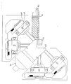
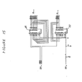
- the conveyor (1), worm (2), and starwheel arrangement (3a & 3b) are conventional and compatible with normal factory operations. These elements are designed to provide a steady supply of cans to the inspection platforms (4).
- a can is fed from the conveyor (1) via the worm (2) into the input starwheel (3a) and deposited on an inspection platform (4). Subsequently, the can will be released to the output starwheel (3b) and delivered back to the conveyor.
- FIG. 1 An important item shown in figure 1 is the eject mechanism (5).
- this air powered piston will be activated to remove the undesirable can from the production line.
- the rectangular item 6 of figure 1 is the base plate which supports the various mechanical items in their proper positions.
- Item 9 is the central shaft of the inspection rotor. More precisely, it is the top view of that portion of the inspection rotor shown in more detail in figure 8.
- Item 10 is the mount for the takeoff gear (16) shown in figures 2 and 7.
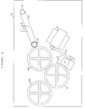
- Figure 2 shows mechanical components used to power the various moving components of figure 1.
- the items shown in figure 2 are all suspended beneath the base plate (6).
- the electric motor (11) powers the gearbox (13) via the V-belt (12). (To keep the drawing simple, gear teeth are not shown on the various engaging components.)
- Gear 14 drives the inspection rotor shaft (21, figure 3), while 15a and 15b drive the starwheels 3a and 3b respectively. Power is taken off 15a by 16 and delivered, through chain 19 and sprocket 17, to drive the worm 2.
- Idler 18 provides chain tension.
- the worm drive is further detailed in figure 7.
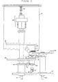
- Figure 3 shows, in side view, the relationships among the inspection rotor (20), an inspection platform (14), an optics module (22), and starwheel (3a or 3b).
- the term 'inspection rotor' refers not just to the specific item labelled 20 in figure 3 but to the whole group of items that rotate around the same central shaft (21) as does plate 20.
- the inspection platform (4) is thus part of the inspection rotor, as is the optics module (22).
- the anti-clockwise rotating starwheel 3a devivers a can to inspection platform 4 (the gear arrangement of figure -2 must provide appropriate synchronization).
- the inspection platform (4) as part of the inspection rotor (20) moves in a clockwise direction around shaft 21 which is driven by gear 14.
- the sun gear (26), idler gear (25) and planetary gear (27) cause the inspection platform (4) to rotate in a counterclockwise direction about the center of its own support shaft (see figure 5).
- This arrangement of counter rotating the can platform (4) as it moves in a clockwise sense from input starwheel (3a) to output starwheel (3b) is used to minimise the shearing forces that the contents of cans undergoing inspection are subject to. For some food products large centrifugal forces may reduce product quality.
- the gearing of rotating elements is such that as the entire inspection rotor rotates 180 degrees in the clockwise direction the inspection platform and can rotate in the opposite direction by (slightly more than) 180 degrees.
- the result of these two motions is to present in excess of 360 degrees of the can seam to the optics with minimum rotation of the can and contents (relative to the fixed frame).
- FIG 3 Also shown in figure 3 is a cam track (23) and cam follower (24).
- a can sitting on can platform (4) would tend to slide off the platform as the inspection rotor moves it from starwheel to starwheel. This is prevented by lifting the can and platform, via the underlying cam (23), so that the double seam of the can is pressed against seam rollers (28, also labelled 70 in figure 9) situated above the can platform.
- the inspection rotor (2.6/1.6) of the present embodiment has four inspection platforms. There is an optics system associated with each. Signal processing circuitry before multiplexing is divided into 2 similar parts. Each part handles data provided by a pair of optical heads opposite each other on the rotor. For such a pair of optical heads, just as one can is about to be examined, its predecessor is being finished. Since there is no overlap in the signals coming from the paired heads the analog multiplexer of figure need only merge the signals from two cans at any one time.
- Item 29 of figure 3 is part of the inspection rotor and revolves with shaft 21.
- the four optics module of the preferred embodiment are suspended beneath plate 29.
- the electronic components that are represented by blocks 12.1 and 12.2 of figure 12.
- the signal processing required to prepare and transmit the gathered data over the fibre optic link to the stationary outside world is performed by electronic components located in card cages mounted on top of plate 29.
- Item 30 is further detailed in figure 8. It performs two functions. First, it has a slip ring arrangement for bringing electrical power to the rotating electronics. Second, it provides a fibre optic link for data to move between the rotating and stationary parts of the system (see the explanation of figure 8). The torque arm 31 prevents item 30 from acquiring the rotation of the inspection rotor.
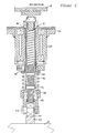
- Figure 4 shows some detail of the inspection rotor shaft 21.
- the rotor shaft housing (32) is supported by baseplate (6).
- Self-centering bearings (34) and bearings (35) allow for rotation of the shaft.
- Provision (36) is made for lubrication the appropriate areas.
- Items 33 are seals.
- Gear 26 is the sun gear of figure 3 which provides the counter-rotation of the inspection platforms (4).
- Drive gear 14 of figure 2 mounts to shaft 21.
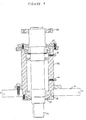
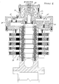
- FIG. 5 shows some detail of the support mechanism for the can platforms (4).
- a rotating cam follower (24) moves along the cam surface (23) which is mounted to the baseplate (6).
- the cam surface is shaped so that the roller (24), shaft (43), and hence platform (4) is in a low position between the output starwheel (3b) and the input starwheel (3a).
- a can if available, is deposited on the platform, and the platform and can are raised by the cam mechanism so that the top double seam of the can is pushed against the seam rollers (28, figure3; 70, figure 9) attached to the optics modules.
- the can platform and can are lowered as the output starwheel is reached.
- the large spring (40) serves to keep the cam follower (24) pressed against the cam (23). Upward movement of gear 27, housing 39, and bracket 42 is prevented because bracket 42 is attached to plate 20 of figure 3.
- the light spring (41) allows the natural variation in nominally identical cans to be compensated for so that each can is securely, but not harshly, pressed against the seam rollers (28,70). (The upward movement of shaft 43 compresses spring 41 to seat the can.)
- FIG. 6 shows more detail of one of the two starwheel assemblies.
- the housing (46) is mounted to the baseplate (6) and has thrust bearings (47) and seals (48) to allow the starwheel drive shaft (49) to rotate.
- Gears 15a or 15b attach to the lower end of the shaft (49).
- the starwheel (3a or 3b) is mounted to the starwheel hub (51) using a shear pin (50) to prevent damage should a misfeed occur.
- Also shown in figure 6 is part of the previously mentioned skidplate (32) which allows a can to be transferred to/from starwheel/can platform.
- the cross section shown in figure 7 provides more detail of the drive mechanism for the worm.
- Gear 16 which is supported beneath the baseplate (6) by the support (10) is driven by gear 15a.
- the chain 19 tranmits the power to gear 17 mounted to shaft 52.
- the idler gear 18 provides chain tension.
- Bevel gears (53) at the top of the shaft (52) tranfer the torque to the worm shaft (56).
- Various bearing (54) allow easy rotation.
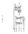
- Figure 8 shows some inner details of item 30 of figure 3.
- the central section (57) rotates as part of the inspection rotor.
- the outer section (30) is stationary. Sliding contact is made between the brushes (58) mounted in the stationary section, and the copper slip rings (59) mounted on the rotating central shaft (an extension to shaft 21). Electrical power can thus be brought to the electronic components mounted on the rotating sections of the machine.
- the outer section (30) is prevented from rotating by a torque arm (31) not shown in figure 8 but found in figure 3. Bearings (60) allow free relative movement of the two sections.
- An infrared transmitter is located in cavity (60) on the center line of rotation.
- optical switch which is one of four mounted on the rotating section.
- the switch is activated every revolution by the protusions (65) of the stationary section. A signal relating to frequency of revolution is thus available. Rotor position can also be determined.
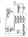
- FIGS 9, 10 and 11 give details of the optics modules (22).
- Each of the four optics modules of the preferred embodiment has camera systems (67) giving four views of the imaged seam.
- a light source (66) provides illumination.
- this light source is a 75 watt quartz-halogen bulb with infrared suppressing coating.
- Item 69 is a reflecting and diffusing chamber which distributes the light properly and which provides appertures through which the cameras may view the seam.
- Each of the camera systems (67) may be moved towards and away from the seam with dowel pins (68) providing a guide.
- the cross hatched section of figure 9 is a cross section of a can guide that serves to correctly position the cans. In planview the guide would be essentially circular. It has an upturned circumferential edge (72) to help guide cans from the input starwheel (3a) to the can platforms (4). A tab (71) at the rear of the guide prevents cans from moving too far in that direction.
- cans on the can platforms (4) are raised against seam rollers and rotated in front of the cameras.
- One of three such equally spaced seam rollers (70), with its supporting post (73), is shown in figure 9 (the other two rollers do not show in the section view).
- a detail of the seam rollers is of importance.
- a small grove is provided in the surface of each roller. They are positioned so that the can seam is located in the groves during inspection. Unwanted can movement is therby prevented.
- Figure 10 is a close up of an individual camera.
- the imaging element is the CCD (charge coupled device)(74).
- An appropriate lens (75) is retained by ring (76) in mount (78).
- This mount may be moved towards and away from the CCD to provide proper focus, and locked in position by a set screw (77).
- a group of three set screws (79), only one of which shows in figure 10, is distributed around the CCD. These may me adjusted so that the seam image falls on the centerline of the CCD.
- the box (80) represents the circuits that are required to drive the cameras and which should be located close to the cameras.
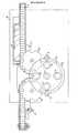
- Figure 11 is a half section of a light chamber (69). Walls (81) are highly reflective, while walls (82) are diffusive. Two appertures (83) through which light can be reflected from the seam to the camera are visible.
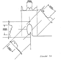
- Figure 30 shows a representation of the curvate surface cross section of a can double seam and the four angles from which the seam is viewed by the CCDs. As can be seen, all or substantially all of the curvate cross section length of the seam falls within the combined field of view of the CCDs. Figure 30 also shows typical output from the CCDs in each of the four views. More will be said about this diagram when discussing signal processing.
- fibre optic bundles could be used for structured lighting of the seam.
- fibre optic bundles could direct reflected light to the four CCDs, bypassing the lens/mirror arrangements.
- the reflected light could be directed to a single CCD and subsequent processing could divide the CCD output into four parts to mimic what is accomplished here.
- the disadvantage of using fibre optic bundles is that the physical size of the presently available fibres and the size/shape of the seam preclude using a sufficient number of fibres to get the resolution that is desired.
- the largest disadvantage of directing images to one large CCD is that the output of the CCD is clocked out serially, so to achieve the same overall machine speed the circuits would have to be driven four times as fast.
- the metal of the double seam contains a pin hole type of fault or perhaps a small dent. Detecting such perforation or dents would be like detecting faults which occur in bottles on bottling lines or sheet metal on rolling lines and which can be detected by any number of mechanisms disclosed in the literature. A well defined defect such as this produces variations in reflected (or transmitted) light which is easy to monitor if the cameras used are arranged to look at the areas of interest.
- detection and classification of defects of the double seam can be carried out by measuring the length of the seam in each of the four views and performing appropriate signal processing.
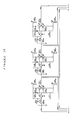
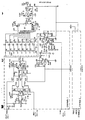
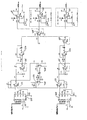
- Figure 12 gives a block diagram of the preferred embodiment of the electronic aspects of the present invention.
- the signal production means (12.1) is further detailed in figures 13 to 16.
- Linear CCDs are used to image the seam of interest.
- Clock signals appropriate to drive the CCDs of figure 13 are provided by circuits of figures 14, 15 and 16.
- Information regarding the double seam is coded in the CCD signals.
- the circuit which extract the appropriate information and which make decisions regarding seam quality are found within blocks 12.4 and 12.5.
- such circuits are located in a reference frame that is stationary, while the optical system and blocks 12.1 and 12.2 rotate.
- more of the circuitry presently depicted to the right of the link in figure 12 could be located on board the rotating platform, it was desirable to have such circuits on the stationary frame to simplify troubleshooting during development of the system. It would be possible, in fact, to locate substantially all of the electronics on the rotating sections and still eject faulty product. However, if real time monitoring of events is desired (for example, to help keep machinery in adjustment so defects are prevented) some signals would still have to be sent to the stationary frame.
- Signal Conditioning Means 1 is needed to prepare the signals for transmission over an optical link
- Signal Conditioning Means 2 is needed to prepare the received signal for subsequent feature extraction on the receiving side of the link.
- Signal Conditioning Means 2 receives a high speed serial digital signal over the fibre optic link and supplies demultiplexed signals to circuitry of 12.4. Further details are found in figures 23 and 24.
- the features extracted by 12.4 are seam lengths and seam start/stop positions. The values of these items are passed to the Digital Processing Means of 12.5 for decision making regarding seam quality.
- the Ejection and Statistical Means 12.6 is rendered in an AT compatible computer. If digital processing means 12.5 finds a can to be defective, it sends a signal to the computer (with which it share a bus) which will, at the appropriate time, cause the eject mechanism (5)to remove the can from the processing line.
- An AT compatible computer has sufficient capability for overall monitoring of machine status but at the same time is relatively inexpensive and well understood. Statistics may be kept regarding items such as eject rates and average seam dimensions and this information is readily transferred from the AT via commercially available networks.
- the four optics modules (22, figure 3) found in the preferred embodiment are equally spaced around the inspection rotor. They are considered to form two pairs of optics modules, where the two members of a pair are at opposite ends of a rotor diameter.
- the circuitry required to perform the signal processing for one pair of modules is essentially duplicated by circuitry required to process the signals for the other pair. However, some signal processing is not duplicated. For instance, there is only one TAXI chip (figure 19) to handle the signals from all four modules. Physically, these unique components (such as the TAXI chip) are located on the PCB boards that process data from one of the optical module pairs.
- That pair of modules, the associated circuitry, and the PCB boards are deemed to be 'local'.
- the other pair, and their circuits and boards are called 'remote' (since they send signals to the unique circuits located on the local boards).
- the two modules forming a pair are further specified as module (or head) A, and module (or head) B.
- FIG 13 shows one of the sixteen Charge Coupled Devices (84) used in the machine (four optics modules x 4 CCDs per module).
- the CCDs used are the TC102 manufactured by Texas Instruments with 128 pixels in a linear array.
- Harris Semiconductor HA5002 buffer (85) which protects the CCD and drives the CCD output over relatively long coaxial cable (86) to the analog circuits of figure 17.
- the clock signals (RCLK,XCLK,TCLK) arrive via the driver circuits of figure 14.
- WRCK is not used in this implementation.
- the clock signals XCLK, TCLK, and RCLK which are used to coordinate data read in the CCDs (84) are produced by the CCD controller circuits of figure 16 and passed to the CCDs via the circuits of figures 15 and 14.
- the CCD controller (87, figure 16) is an EPLD (Erasable Programmable Logic Device) manufactured by Altera and called by them the EPf900DC.
- Listing 1 provides the information necessary to duplicate the EPLD structure used here. From an original clock signal (CLOCK) produced by figure 20, this chip produces X,T, & R CLK signals with the correct shape and timing for reading data from a CCD (84). These signals are then operated on by therotating latches (88) of figure 15 to provide the properly timed signals for reading all four CCDs of a given optical module (22).
- CLOCK original clock signal
- X,T, & R CLK signals with the correct shape and timing for reading data from a CCD (84).
- EPLD 87 also generates the low frequency clock pulses START and STOP which are used by the data encoder (89) of figure 18.
- Figure 14 shows the final circuits required to make the various clock signals output from figure 15 suitable for driving the CCDs. Two functions are performed--level shifting and driving of the high impedence clock inputs. One such circuit is needed for each CCD.
- the EPLD (87) in conjunction with latch 91, generates the 4 strobe signals (STRB1,..,STRB4) which are provided (for figure 17) to maintain the video signals on a constant DC level corresponding to the level of the black level pulses.
- a further feature revealed in figure 16 is the clock signal (ADC CLOCK) used by the Analog to Digital converter of figure 18. It is provided by a digital delay device from Dallas Semiconductor (10.2) (item DS1000). Through jumpers, adjustments can be made for various signal propagation times that characterize nominally identical machines. It is used to control the analog to digital converter (90), data encoder (89) and some latches of figure 12. It is desirable that the timing signals be such that the CCD output arrives at the ADC during the low phase of the clock. This insures that the ADC sees the input data when it is stable and allows the use of a cheaper ADC than would otherwise be the case.
- Another digital delay device (92) provides the FFWR signal for the fifos (94) of figure 19 (pins labelled -WR).
- CLKA and CLKB are provided by the buffers 94. These are the CLK inputs for the latches (88) of figure 15.
- a and B signify signals for the local and remote heads respectively.
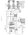
- the CLK signal of figure 15, and the ADC CLOCK signal of figure 16 are derived from the system clock signal (CLOCK) of figure 20.
- the voltage controlled oscillator (95) provides a clock signal dependant upon the voltage supplied to the device (some wave shaping is applied to the output signal).
- the voltage supplied is determined by the digital to analog converter (96) which has inputs supplied by the PROM (97).
- the relationship between machine speed and proper clock rate is non-linear and the PROM is used to contain the required mapping, which can be found in Listing 2 (the PROM is a 2716, 4K in size).
- Inputs to the PROM are via the latch (98).
- the digital values supplied to the latch, and PROM may originate in one of two ways.
- the EPLD (99) (see listing 3) will supply the values. It has its own clock (100) and an input (SPEED) from the optical switch (64) of figure 8 which counts revolutions of the machine rotor. In this way, the value of CLOCK is related to the operating speed of the machine.
- the alternative method of supplying values to the PROM (97) is via the DIP switches (101).
- the EPLD (99) will not provide data and the values given to the PROM will be determined by the DIP swithces (101)
- the reason for having the two sources of input to the PROM is as follows:
- the EPLD (99) provides values that depend upon actual machine speed. When the machine rotor is stationary no value is output and the system clock does not operate. However, for trouble shooting purposes it may be desirable to insert a can into the stationary machine and examine the data that would be gathered if the clock were operational. The DIP switches allow this to be done. Of course, if the machine, in operation, is used at only one speed the flexibility provided by the EPLD (99) is not required.
- the NEWCAN signal allows the latch 14.4 to release its data only when a can is actually in front of the cameras.
- Figure 21 shows the origin of this NEWCAN signal.
- the CCD DATA is the digital data from the view 2 camera (see Figure 30). It is compared (102) to a preset threshold value to determine the presence of a can (a can in place produces more reflection than the empty space).
- the EPLD (103) (see listing 4) provides the NEWCAN signal to figure 20 and the CANIN (and AORB) signals to figure 19.
- the AORB signal codes whether the data comes from the local of remote inspection heads.
- the circuit shown can be divided into two parts.
- the initial analog part is duplicated 7 more times to handle the 8 cameras that may be in use at any one time.
- the input signal VID1 is the output from one of the CCDs.
- Each of the 8 channels inverts and amplifies the video signals coming from a CCD.
- Each channel also has two other inputs.
- Gain control (AGC1) is provided via the circuit shown in figure 22.
- Black level restoration is provided via the STROBE1 signal originating in figure 16.
- the second part of the circuit shows the 8 filters and the analog multiplexor (104) that is used to multiplex signals from the 8 channels.
- the output analog video signal is amplified on its way to figure 18.
- Figure 18 shows the multiplexed video signal of figure 17 being amplified (105) before passing to an analog to digital converter (90).
- the ADC CLOCK controlling the converter, and following latch, comes from figure 16 and ultimately from the system clock of figure 20.
- EPLD (89) is a data encoder which serves to add start and stop bytes to the data train.
- Listing 5 provides the code for this EPLD (89).
- the START and STOP pulses controlling this device are generated by EPLD (87) of figure 16.
- the data encoder reserves values '00' and 'FF' for control bytes. Input data that has the value '00' is given the value '02'. Similarly, input data 'FF' is set to 'FE'. The EPLD will set the output data to 'FF' only when the STRT input is high.
- the principal components of figure 19 are the TAXI chip (106)) and the EPLD (107) which controls it.
- the TAXI is an AM7968 produced by Advanced Micro Devices. As input it receives the 8 bit parallel data from latch (108); as output it produces a serial stream for the line transmitter (108b). Output from this ECL device is sent to the infrared transmitter located in cavity (61) of figure 8.
- Input to the latch (108) comes from one of four sources.
- the four inspection heads of the machine are divided into two pairs. Due to the machine geometry, only one inspection head of each pair may be examining a can at any given time. Data from either of the 'local' heads arrives through one of the FIFOs (94); data from the 'remote' heads through the other FIFO (94).
- the latches (109) provide the other two sources of input: diagnostic signals form either the remote of local boards. A full byte is available for such diagnostics but in the present embodiment only two bits are used--A/B and CANIN.
- the A/B switch indicates for each pair of optical heads (local & remote) which optical head is providing data.
- the CANIN bit indicates whether or not a can is actually in front of the cameras. Both signals are provided by EPLD (103) of figure 21.
- the EPLD (107) has to determine which of the 2 fifos or which of the 2 latches to enable.
- the enabled device gets to clock its contents into the TAXI (106).
- the enabling is done according to a fixed sequence.
- the cycle for the EPLD is 1)put out command bits (COMOO to COM03) 2) read the diagnostic latches 3) read the fifos.
- the NEWCAN signal (NEWCAN 0 for local heads, NEWCAN 1 for remote heads) is used to begin the cycle. This signal comes from figure 21.
- the TAXI (106) will send commands if either C0, C1, or C2 is active.
- the TAXI receiver EPLD (115) will detect the command sequences in the data stream and react appropriately.
- Figure 22 shows the gain control circuits for one pair of optic modules. The output signals are used by the analog circuits of figure 17. Potentiometers (110) may be manually adjusted to vary the DC voltage levels. In future the potentimeters will be replaced with circuits to provide automatic adjustment of the gain.
- Figure 23 provides for the high speed serial data which has been transmitted over the link, to be converted back to a parallel form.
- Item 111 is a MECL receiver (MC10116) and 112 is the TAXI receiver (AM7969) which actually produces the parallel data from the input serial stream.
- Latches 113 receive the diagnostic data for the local and remote cameras.
- Latches 114 receive the image data for local and remote cameras.
- DSTRB tells EPLD (115) to clock the data.
- CSTRB causes the command data to be clocked.
- Figure 24 performs two functions. First, it demultiplexes the data coming from figure 23.
- the demultiplexer (116) monitors the data stream.
- the data encoder 89 of figure 18 reserved 'FF's for marking the beginning of scan lines and '00's to mark the end.
- Upon detection of an 'FF' in the data the demultiplexing cycle begins.
- Data is encoded in the order view 1, view 2, view 3, view 4. More precisely the data is in the order: pixel 1 of view 1, pixel 1 of view 2,..,pixel 1 of view 4, pixel 2 of view 1,..,pixel 2 of view 4,...,pixel 128 of view 4.
- the data is read into the four latches (117) under control of the demultiplexer (116), with all data for a given view going to a particualr latch.
- the counter (118) is used to count the number of pixels passed to the latches (117).
- the comparator (119) and associated DIP switches are provided to control the number of pixels passed to the latches.
- the normal setting is 128.
- the second function of the figure 24 is to provide'the delay clock (LATCHIN)????that is used to produce the delayed signal (figure 25) that is subsequently used by the edge detection circuits of figure 26.
- Figure 25 shows the simple circuitry which takes data from one of the output latches (117) (i.e. the data for one view) of figure 24 and provides two signals to the following analog circuitry of figure 26.
- the arriving data is passed through a direct register 121 and also the delay providing registers 122.
- the delay registers used can handle only four bits so a pair of them is needed.
- the delay registers 123 produce a delayed signal which could be used by subsequent analog circuits for the extraction of curvature information from the data.
- curvature information is not used in the decision about seam quality. It is anticipated that a future version of the machine will make use of such data.
- the required clock signals are provided by EPLD 116 of figure 24.
- PIXCLK determines how much delay to provide.
- the direct and delayed signals from a given camera are each passed through digital to analog converters 124 of figure 26.
- the two signals are 8 bits wide and of identical shape and amplitude. They differ only in phase.
- Each analog signal is acted on by a low pass filter 125, and amplifier 126. This latter item also acts as a 'super diode', cutting off any negative parts of the signal.
- a voltage follower 127 acts on the delayed signal only.
- the differential amplifier 128 subtracts the two signals.
- the signal appearing on this amplifiers output contains both positive and negative parts which correspond to rising and falling edges in the original video signal.
- the comparators 129 and 130 produce standard logic pulses from the amplifier output. Potentiometers 131 allow the threshold for the comparators to be adjusted.
- the two video signals are kept on a common DC level, corresponding to a minimal value of the non-delayed signal, by 132 acting (in a peak detector configuration) in conjunction with amplifiers 133.
- Figure 27 shows an EPLD (134) and a set of latches which together provide data to subsequent digital processing circuits.
- the COMPA and COMPB signals from the preceeding analog edge detection circuits are inputs to the EPLD.
- the function of the EPLD is to determine the start and stop locations of the seam edges (ie at which pixel, of the 128, the seam begins and ends), and to determine the length of the seam, at each scan position.
- start positions are latched out through 135 to figure 28.
- stop positions are passed through latches 136 and the lenghts through 137.
- Latches 138 anticipate future development when curvature information will be used in the decision making.
- the length is the critical component of the digital processing scheme.
- Listings 9a-9d provide the information required to program the four different EPLDs required for the four different views. Since the data from each view has a different characteristic shape (see figure 30) different devices are required to detect the correct risingifalling edges.
- figure 30 shows the outline of a double seam. It also shows typical CCD output for each of the four views of the present embodiment.
- the analog edge detection circuits of figure 26 produce pulses with each significant rise and fall of CCD output, but seam lengths can be extracted from the data only if the correct edges are dealt with. It is quickly apparent why there were two variations of the analog circuits in figure 20.
- view 1 a strong rising edge is characteristic of the beginning of the seam and a strong falling edge is characteristic of its end.
- view 3 shows a strong rising edge marks the start of the seam, it is only the rising edge that results from reflection off the bottom of the countersink that can be readily detected.
- the length in view 2 is similarly marked by two rising edges.
- the long slow decline in light levels as we pass down the seam is quite unsuitable for reliably triggering circuits. There is, notably, a small but significant increase in light level as we pass to the flat surface of the can body.
- the digital controller of figure 27 (EPLD 134) is programmed to 'close its eyes' to edges in certain areas.
- the risign edge characteristic of the outside edge of the seam has been detected. Since the seam has a characteristic width, the falling and rising pulses that mark the top of the seam can be ignored. The controller will only start looking for a falling edge when it is dealing with pixels that are safely passed the region marking the seam top.
- each view has its own characteristics and it is only experience with a particular type of can that will reliable determine what sorts of thresholds to use.
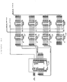
- Figure 28 shows the interface between the output of figure 27 and a commercially available digital processing board which operates upon that output.
- This interface is essentially a dual port RAM with two banks of memory.
- Data from figure 27 arrives via the 8 bit data bus and is temporarily stored in one of two 64K memory sections (139 + 140 or 141 + 142).
- the incoming data is the series of start and stop positions and lengths for each of the approximate 2000 scan locations, for each of the four views, for each can.
- the structure of the data is: starting pixel of scan line n, stop pixel for scan line n, length of scan line n, no signal (or curvature), starting pixel for scan line n + 1, ...
- the memory bank to which the data is directed is controlled by the ABSEL signal from the controller chip 144 of figure 29.
- This same EPLD also determines the addresses in which the data will be temporarily placed.
- Lines C12-C15 (of EPLD 144) select the most significant bits for the address and the counter 145, running at 1/16 the rate, determines the least significant bits.
- figure 28 The essential operation of figure 28 is as follows: incoming data is sent to a given memory bank such that view 1 and view 2 data are placed in RAM 140 and view 3 and view 4 data is placed in RAM 139. Within the view 1 data, the 2000 or so start positions are continguous. Similarly the 2000 or so end positions and 2000 or so lengths are stored together. Similarly for each of the other views.
- the DSP board may access the data from the previous can (stored in 139 &140) via its own bi-directional bus and port 143. (To perform a memory test the DSP board may write into the dual port RAM via port 144). Because of the contiguous blocks of memory, the DSP can get the information it needs (ie the length values) very rapidly once access is begun.
- Listing 10 gives the code used to program EPLD 144.
- the output data flow from figure 28 is an 8 bit wide stream. For any given can, the starting pixel for each of the approximately 2000 scans is transmitted, then the ending pixel for each scan, and then the length (in pixels) for each scan. Provision is also made for further information (curvature) to transmitted. After all the information for view 1 is transferred, view 2, 3, and 4 are handled in turn.
- the digital processing board that uses this data is a commerically available unit called the TMS320C25 and available from SPECTRUM Signal Processing Inc.
- the board has built-in A/D interfaces which are not used in the present project. It plugs into any PC expansion bus. Details regarding the board can be obtained from the vendor.
- the function of the board is to analyze the incoming data and determine when seam conditions are abnormal. None of the decision procedures so far implemented on the DSP board uses the absolute start and stop position data. Adequate results have been obtained using only the length of each scan line (which of course depends upon the relative start/stop positions.
- the process begins when the DSP board receives an interupt signal from the APP to indicate that data is ready.
- the DSP interrupts the PC to indicate a NO CAN signal, and the DSP enters IDLE mode;
- the DSP reads the Number of Scan Lines value from the APP.
- the DSP interupts the PC with a TOO MANY or TOO FEW scanlines signal
- the DSP will read in all of the scan lines from all 4 views from the APP.
- the initial stage of analysis treats the data from each of the 4 views separately.
- the notation s(v,i) indicates the scan line value in view v at position i where v ranges from 1 to 4, and i ranges from 0 to the total number of scan lines for that view (it is somewhat larger than 2000 in the present embodiment).
- the scan line data from each view is smoothed to eliminate the high frequency component of the signal.
- the following low pass filter is applied to the data for each view independently.
- sms(v,i) s(v,i) * (exp(k)-1 ) + sms(v,i-1) * exp(k)
- sms(v,i) indicates the value of the smoothed signal at position i, in view v and where k is a predefined constant.
- the values of exp(k) are found using a look up table.
- a running average for the scan line value, at each scan line position, is now determined.
- rav(v,i) indicates the value of the running average in view v at scan line i.
- rav(v,i) ⁇ SUM[from i-512 to i] of sms(v,i) ⁇ /512 where SUM[from..to..] indicates a summation over the specified limits.
- 512 lines are used to provide the running average because it is of reasonable size and for the particualr DSP board used, division by 512 is a simple register shift to the right. To get the process started a header of 512 scan lines (the last 512 scan lines) is tacked to the front of the list of scan lines.
- defect vector #1 is the 3-tuple (peak,300,400) where peak is the maximum deviation of the seam length from the running average of the seam lengths. That is, for the view under consideration, there is a 'defect' extending between scan line 300 and scan line 400 and it has a maximum deviation of 'peak' pixels.
- This process of creating defect vectors continues until all 2000 scan lines have been processed. The result is a set of zero or more vectors that represent possible defects. More processing is performed before the final decision regarding the existence of defects is made.
- the present embodiment is designed such that if the number of defect vectors for any view is greater than 32 then the PC will be interupted and all processing of that can will stop. Such a large number of defect vectors indicates a badly damaged seam, or else there is too much signal noise--in either case processing ceases and the can is ejected by the air powered piston of figure 1.
- the original defect vectors are now 'merged'. That is, defects that are within a predefined distance of each other are considered as part of one larger defect.
- a new vector replaces the two.
- the peak component of the replacement vector is the larger of the two contributing vectors.
- the start component of the new vector is the start position of the first vector: the end component of the new vector is the end position of the second vector.
- the next stage of processing is to compare the lengths and peaks of the various merged defect vectors to predetermined minimum values.
- Defect vectors representing short lived variations, or longer lived but not extreme variations are discarded.
- These minimum values are obviously important to the decision making of the machine.
- the appropriate choice of constants can be made by educated trial and error. The values obviously depend upon the specifics of the machine. They may also vary with the type and size of can being used. Although tedious, experience with a range of defects, in a specific type of can, will provide reasonable values for the various constants.
- defect vectors may be sufficient cause to eject cans as defective. It may also be noted that the value of the peak component of the vectors can be positive or negative depending upon whether the deviation in seam length from the running average was due to abnormally short or abnormally long seam lengths. This immediately gives us some information about the type of fault that may be present in the can seam.
- Figure 32b shows a fractured seam.
- the length in view 2 has been found to be shorter than normal because the edge detection circuitry has detected the edge at the beginning of the fracture.
- seam defects normally affect the images in more than one view.
- One type of fault may produce a long seam length in views 1 and 2 and a short length in view 3.
- Another type of fault may produce a long vector in view1 but short vectors in views 2 and 3.
- the DSP will classify the type of fault when it detects such characteristic combinations. It is difficult to give a mapping, in advance, from defect vector combinations to type of fault. A general procedure can be outlined for determining such mappings.
- the DSP board has access to the following seam information: start positions of the seam, stop positions of the seam, and length of the seam, for each scanning position, for each of the views.
- the DSP board resides on the PC bus.
- Any skilled in the appropriate art can use this information to produce graphical displays that are highly useful. For instance, a bar chart of the 2000 or so seam lengths can be displayed. This might be overlayed with defects that are determined from the DSP processing. The defects that are aligned by the DSP might be further highlighted. By examining such displays, especially when the corresponding can is available, it is possible to tune the machine for good performance. Changes made to the various thresholds may be evaluated.
Landscapes
- Engineering & Computer Science (AREA)
- Physics & Mathematics (AREA)
- General Physics & Mathematics (AREA)
- Health & Medical Sciences (AREA)
- Computer Vision & Pattern Recognition (AREA)
- Theoretical Computer Science (AREA)
- Quality & Reliability (AREA)
- Life Sciences & Earth Sciences (AREA)
- Chemical & Material Sciences (AREA)
- Analytical Chemistry (AREA)
- Biochemistry (AREA)
- General Health & Medical Sciences (AREA)
- Immunology (AREA)
- Pathology (AREA)
- Investigating Materials By The Use Of Optical Means Adapted For Particular Applications (AREA)
Applications Claiming Priority (2)
| Application Number | Priority Date | Filing Date | Title |
|---|---|---|---|
| CA560755 | 1988-03-07 | ||
| CA560755 | 1988-03-07 |
Publications (2)
| Publication Number | Publication Date |
|---|---|
| EP0332376A2 true EP0332376A2 (de) | 1989-09-13 |
| EP0332376A3 EP0332376A3 (de) | 1990-10-10 |
Family
ID=4137585
Family Applications (1)
| Application Number | Title | Priority Date | Filing Date |
|---|---|---|---|
| EP19890302222 Withdrawn EP0332376A3 (de) | 1988-03-07 | 1989-03-06 | Apparat zur Inspektion von Umbördelungen bei Blechdosen und ähnlichem |
Country Status (2)
| Country | Link |
|---|---|
| US (1) | US5017795A (de) |
| EP (1) | EP0332376A3 (de) |
Families Citing this family (12)
| Publication number | Priority date | Publication date | Assignee | Title |
|---|---|---|---|---|
| US5386293A (en) * | 1994-02-22 | 1995-01-31 | Barnard; Ronald G. | Seam inspection device |
| US6370304B1 (en) * | 1998-09-28 | 2002-04-09 | Corning Cable Systems Llc | Radiation marking of fiber optic cable components |
| TW419634B (en) | 1999-02-02 | 2001-01-21 | Ind Tech Res Inst | Automatic detection system and method using bar code positioning |
| DE19930536C2 (de) * | 1999-06-28 | 2001-07-05 | Manfred Kuhnke | Vorrichtung zur Messung eines Dosenfalzquerschnittes |
| JP5801098B2 (ja) * | 2011-05-06 | 2015-10-28 | 日本電産トーソク株式会社 | 金属缶端部の巻締検査装置及び検査方法 |
| US9555616B2 (en) | 2013-06-11 | 2017-01-31 | Ball Corporation | Variable printing process using soft secondary plates and specialty inks |
| ES2734983T3 (es) | 2014-12-04 | 2019-12-13 | Ball Beverage Packaging Europe Ltd | Aparato de impresión |
| US10549921B2 (en) | 2016-05-19 | 2020-02-04 | Rexam Beverage Can Company | Beverage container body decorator inspection apparatus |
| CN109476150B (zh) | 2016-07-20 | 2021-07-02 | 鲍尔公司 | 用于对齐装饰器的墨件的系统和方法 |
| US11034145B2 (en) | 2016-07-20 | 2021-06-15 | Ball Corporation | System and method for monitoring and adjusting a decorator for containers |
| US10809052B1 (en) * | 2018-09-19 | 2020-10-20 | Onevision Corporation | System for measuring crimped container seams |
| CN110308113B (zh) * | 2019-07-04 | 2021-06-22 | 中南林业科技大学 | 一种用于近红外光谱检测的全方位翻转准球形水果装置 |
Family Cites Families (5)
| Publication number | Priority date | Publication date | Assignee | Title |
|---|---|---|---|---|
| SE8105051L (sv) * | 1981-08-26 | 1982-08-30 | Kockumation Ab | Forfarande for indikering av ett foremals nervaro i en metzon och anordning for genomforande av forfarandet |
| GB2175396B (en) * | 1985-05-22 | 1989-06-28 | Filler Protection Developments | Apparatus for examining objects |
| US4832173A (en) * | 1985-05-31 | 1989-05-23 | Kirin Beer Kabushiki Kaisha | Device for rotating containers while transporting same |
| DE3686988D1 (de) * | 1985-08-12 | 1992-11-26 | Hegenscheidt Gmbh Wilhelm | Einrichtung zur vermessung von im fahrzeug eingebauten raedern von radsaetzen. |
| WO1988008970A1 (fr) * | 1987-05-06 | 1988-11-17 | Toyo Seikan Kabushiki Kaisha | Procede d'inspection de la soudure de boites |
-
1989
- 1989-03-06 EP EP19890302222 patent/EP0332376A3/de not_active Withdrawn
-
1990
- 1990-05-07 US US07/519,322 patent/US5017795A/en not_active Expired - Fee Related
Also Published As
| Publication number | Publication date |
|---|---|
| US5017795A (en) | 1991-05-21 |
| EP0332376A3 (de) | 1990-10-10 |
Similar Documents
| Publication | Publication Date | Title |
|---|---|---|
| CN101061382B (zh) | 用来检测多个填满容器中异物或缺陷的方法和装置 | |
| US5017795A (en) | Apparatus for inspecting can seams and the like | |
| CA1228136A (en) | Surface inspection apparatus | |
| US4079416A (en) | Electronic image analyzing method and apparatus | |
| US4496056A (en) | Automated inspection system | |
| US4488648A (en) | Flaw detector | |
| EP3654275B1 (de) | Verfahren und system zur automatischen messung physikalischer und dimensionaler parameter von mehrsegmentartikeln | |
| EP0293510A2 (de) | Vorrichtung zur Prüfung der Seitenwand einer Flasche | |
| KR101509260B1 (ko) | 용기 검사 중에 용기의 회전을 보장하는 장치 및 방법 | |
| CA1313240C (en) | Apparatus for inspecting can seams and the like | |
| GB1571836A (en) | Electronic image analyzer method and apparatus | |
| JPS6056245A (ja) | 自動表面検査装置における入力装置 | |
| US3799682A (en) | Apparatus for feeding polished machine parts past optical scanning means to enable inspection of the polished parts | |
| JP3023004B2 (ja) | 筒状体外面検査装置 | |
| JP3093784B2 (ja) | 筒状体内面撮像装置及び筒状体内面検査装置 | |
| GB2174196A (en) | Container finish inspection apparatus | |
| JP2992110B2 (ja) | 筒状体検査装置 | |
| JP2986235B2 (ja) | 検査装置 | |
| JP2823684B2 (ja) | 信号伝送装置 | |
| JP3023005B2 (ja) | 照度検査装置 | |
| JP3023016B2 (ja) | 画像処理装置 | |
| JP3091268B2 (ja) | 筒状体内底面検査装置 | |
| SU1578470A1 (ru) | Устройство контрол внешнего вида деталей типа "втулка | |
| JP3103589B2 (ja) | 筒状体内底面撮像装置及び筒状体内底面検査装置 | |
| JP2989706B2 (ja) | 画像処理装置 |
Legal Events
| Date | Code | Title | Description |
|---|---|---|---|
| PUAI | Public reference made under article 153(3) epc to a published international application that has entered the european phase |
Free format text: ORIGINAL CODE: 0009012 |
|
| AK | Designated contracting states |
Kind code of ref document: A2 Designated state(s): BE CH DE ES FR GB GR IT LI NL |
|
| PUAL | Search report despatched |
Free format text: ORIGINAL CODE: 0009013 |
|
| AK | Designated contracting states |
Kind code of ref document: A3 Designated state(s): BE CH DE ES FR GB GR IT LI NL |
|
| 17P | Request for examination filed |
Effective date: 19910614 |
|
| 17Q | First examination report despatched |
Effective date: 19930301 |
|
| STAA | Information on the status of an ep patent application or granted ep patent |
Free format text: STATUS: THE APPLICATION IS DEEMED TO BE WITHDRAWN |
|
| 18D | Application deemed to be withdrawn |
Effective date: 19950525 |