EP0331925B1 - Filtre d'aiguillage - Google Patents
Filtre d'aiguillage Download PDFInfo
- Publication number
- EP0331925B1 EP0331925B1 EP89102292A EP89102292A EP0331925B1 EP 0331925 B1 EP0331925 B1 EP 0331925B1 EP 89102292 A EP89102292 A EP 89102292A EP 89102292 A EP89102292 A EP 89102292A EP 0331925 B1 EP0331925 B1 EP 0331925B1
- Authority
- EP
- European Patent Office
- Prior art keywords
- branch
- frequency range
- point
- inductance
- way
- Prior art date
- Legal status (The legal status is an assumption and is not a legal conclusion. Google has not performed a legal analysis and makes no representation as to the accuracy of the status listed.)
- Expired - Lifetime
Links
- 239000003990 capacitor Substances 0.000 claims abstract description 13
- 238000000926 separation method Methods 0.000 claims description 3
- 230000003071 parasitic effect Effects 0.000 claims 1
- 230000005540 biological transmission Effects 0.000 abstract description 10
- 230000000694 effects Effects 0.000 abstract description 3
- 230000001747 exhibiting effect Effects 0.000 abstract 1
- 230000001771 impaired effect Effects 0.000 abstract 1
- 230000008878 coupling Effects 0.000 description 2
- 238000010168 coupling process Methods 0.000 description 2
- 238000005859 coupling reaction Methods 0.000 description 2
- 230000006866 deterioration Effects 0.000 description 2
- 238000004804 winding Methods 0.000 description 2
- 230000002411 adverse Effects 0.000 description 1
- 230000000903 blocking effect Effects 0.000 description 1
- 238000012769 bulk production Methods 0.000 description 1
- 238000011161 development Methods 0.000 description 1
- 230000018109 developmental process Effects 0.000 description 1
- 238000010586 diagram Methods 0.000 description 1
- 230000002349 favourable effect Effects 0.000 description 1
- 238000009434 installation Methods 0.000 description 1
- 238000004519 manufacturing process Methods 0.000 description 1
Images
Classifications
-
- H—ELECTRICITY
- H03—ELECTRONIC CIRCUITRY
- H03H—IMPEDANCE NETWORKS, e.g. RESONANT CIRCUITS; RESONATORS
- H03H7/00—Multiple-port networks comprising only passive electrical elements as network components
- H03H7/46—Networks for connecting several sources or loads, working on different frequencies or frequency bands, to a common load or source
- H03H7/461—Networks for connecting several sources or loads, working on different frequencies or frequency bands, to a common load or source particularly adapted for use in common antenna systems
Definitions
- the invention relates to a crossover network according to the preamble of claim 1.
- a crossover network is known, for example, from the "Wak 202" device of the applicant, the basic circuit of which is shown in FIG.
- the remote feed current is delivered or required in the further cable run of the high-pass branch.
- the longitudinal element of the high-pass branch is bridged by a choke D and a separating capacitance C is provided in the longitudinal branch of the low-pass filter.
- This known crossover which can be made suitable for remote feed with little effort, works satisfactorily in the VHF range.
- the invention is therefore based on the object of a crossover To further develop in accordance with the preamble of claim 1 that the remote feed means cause only a minimal deterioration in the high-frequency transmission properties of the crossover in a simple and inexpensive manner even at high frequencies and supply currents.
- the remote supply voltage is applied directly to the branch connection, so that the decoupling between the connections of the two branches is not optimal for a higher and a lower frequency range, but is lower compared to an otherwise identical crossover network without remote supply.
- This deterioration in the coupling attenuation between the connections mentioned can be avoided in a simple manner by providing at least two longitudinal coils in the branch for the lower frequency range and, according to claim 3, the remote feed connection having as many longitudinal inductances as possible with the disconnection or interconnection point of the crossover on the one hand and the connection point of this branch is connected on the other hand. With an even number of coils, this division can be implemented exactly. In the case of an odd number of series inductors, however, this only applies if the center coil can be tapped; otherwise it is usually cheaper to provide the remote feed connection between the middle coil and the coil following next to the branch connection point.
- the disruptive influence of the stray capacitance of the choke on the transmission properties in the lower frequency range, in particular their return loss, is noticeably reduced. If the capacitance is not only used as a block capacitor, but also by appropriate dimensioning together with the stray capacitance of the choke to increase the filter edges in the lower frequency range, multiple use of this component is achieved with the least possible effort.
- An embodiment of the remote feed choke according to claim 5 means a slightly higher production cost, but the winding capacity is lower than with a single large choke and thus, as desired, the influence reducing the decoupling of the two branch connections is significantly reduced.
- the smaller partial chokes noticeably reduce the quality of a series resonant circuit which is switched on for the flank distribution as a cross member in the branch for the higher frequency range.
- FIG. 1 shows a remote feed switch according to the prior art.
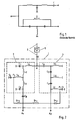
- FIG. 2 shows a circuit diagram of an exemplary embodiment of the crossover according to the invention in an application as an antenna outlet for use in a communal installation for the transmission of terrestrial and satellite radio signals.
- the crossover 1 of the antenna end socket is connected to this at the receiver end of a trunk line 2 at the separation point A and consists of a low pass 3 for the frequency range up to 860 MHz (terrestrial television), which is continued at connection A 1 to a television set, and a high pass 4 for the frequency range from 950 MHz (first satellite intermediate frequency range), which is continued at connection A2 (originally right-hand circularly polarized satellite signals) to a satellite tuner connected to the television.
- the low-pass filter 3 consists of three longitudinal inductors L1, L2, L3 and, accordingly, three transverse capacitances C1, C2, C3 connected to ground.
- the middle cross member contains to increase the filter edge at the upper end of the UHF range between the capacitance C2 and the connection point of the inductors L2 and L3 switched on inductor L4.
- the high-pass filter 4 consists, analogously to the low-pass filter 3, of three longitudinal capacitors C4, C5, C6 and three transverse inductors L5, L6, L7.
- the directly connected to the connection A2 cross inductance L7 is by a capacitance C7 connected to ground to a series resonant circuit for steepening the filter edge at the lower end of the first satellite intermediate frequency range.
- the interconnection point P1 of the transverse inductance L7 and the capacitance C7 of the high-pass filter 4 is connected via a choke Dr2 with a smaller inductance, a choke Dr1 with a larger inductance and a further choke Dr2 with the cross-inductance L4 and the capacitance C2 of the low-pass filter 3 connecting the switching point P2.
- a remote supply direct current supplied from the satellite tuner is via the socket connection A2 for the originally right circularly polarized satellite signals, the transverse inductance L7, the chokes Dr2, Dr1 and again Dr2 and the inductors Lmaschineen, L2, L1, the RF input E of the crossover 1 and the main line 2 fed to an amplifier 5 for its operating power supply.
- C7 by appropriate dimensioning simultaneously blocks the DC supply and, together with the stray capacitance, in particular the choke Dr2 connected to the interconnection point P1 and the inductance L7, the already mentioned edge distribution of the high-pass filter 4. Accordingly, C2 acts on the one hand as a block capacitor and, on the other hand, results in particular together with the stray capacitance the choke Dr2 connected to the switching point P2 and the inductance L4 the desired edge distribution at the low-pass filter 3.
- C1 is also effective as a block capacitor, C4 prevents a short-circuit of the remote supply direct current via L5 and C8 its drainage through the connection A1.
- the switching of the crossover according to the invention can be done in be carried out in the same way, except that the inductance of the two partial chokes Dr2 is different and the smaller one is to be connected to the interconnection point P1.
Landscapes
- Filters And Equalizers (AREA)
- Surgical Instruments (AREA)
- Piezo-Electric Or Mechanical Vibrators, Or Delay Or Filter Circuits (AREA)
- Dry Shavers And Clippers (AREA)
- Oscillators With Electromechanical Resonators (AREA)
- Networks Using Active Elements (AREA)
- Input Circuits Of Receivers And Coupling Of Receivers And Audio Equipment (AREA)
- Medicines That Contain Protein Lipid Enzymes And Other Medicines (AREA)
- Control Of Motors That Do Not Use Commutators (AREA)
- Transplanting Machines (AREA)
- Luminescent Compositions (AREA)
- Superconductors And Manufacturing Methods Therefor (AREA)
- Display Devices Of Pinball Game Machines (AREA)
Claims (5)
- Filtre d'aiguillage pour séparer une gamme de fréquence totale en deux gammes des fréquences partielles ou, respectivement, pour les interconnecter, qui sert à alimenter par distance un courant de service dans le point de connexion d'une branche d'une gamme des fréquences plus hautes, cette branche possédant au moins une capacité en série et une inductance transversale raccordées au point de connexion,
caractérisé par les faits que l'inductance transversale (L₇) qui est connectée au point de connexion (A₂) de la branche (4) pour la gamme partielle des fréquences plus hautes est connectée à terre par un condensateur de blocage (C₇) et que le point d'interconnexion (P₁) de ces deux réactances (L₇, C₇) est connecté par une bobine de réactance (Dr₁, Dr₂) à un point de circuit (P₂) d'une branche (3) d'une gamme partielle des fréquences plus basses qui est connecté par au moins une inductance (L₁, L₂, L₄) au point de séparation (A) ou, respectivement, le point d'interconnexion du filtre d'aiguillage fréquence (1). - Filtre d'aiguillage comme en demande 1, caractérisé par les faits que le condensateur de blocage (C₇) est dimensionné tant que en combinaison avec l'inductance transversale (L₇) connectée en série et avec la capacité parasitaire de la bobine de réactance (Dr₂) il cause un accroissement de la pente du flanc des caractéristiques filtre de la branche (4) pour la gamme partielle des fréquences plus hautes.
- Filtre d'aiguillage selon demandes 1 ou 2 avec au moins deux inductances en série dans la branche (3) pour la gamme partielle des fréquences plus basses, caractérisé par les faits que le point d'interconnexion (P₂) est connecté, si possible, par le même nombre des inductances en série (L₁, L₂, L₄ ou L₃, L₄, respectivement) avec le point de séparation (A) ou, respectivement, le point d'interconnexion du filtre d'aiguillage (1) dans une coté et le point de connexion (A₁) de cette branche (3) dans l'autre coté.
- Filtre d'aiguillage selon une des demandes 1 à 3, caractérisé par les faits que la branche (3) pour la gamme partielle des fréquences plus basses possède au moins un élément transverse désigné comme circuit de résonance en série, l'inductance (L₄) étant connectée à l'élément en série et sa capacité (C₂) étant connectée à la terre, et que le point d'interconnexion de ces deux réactances (L₄, C₂) constitue le point de circuit (P₂).
- Filtre d'aiguillage selon une des demandes 1 à 4, caractérisé par les faits que la bobine de réactance consiste au moins de deux bobines de réactance partielles (Dr₁, Dr₂) avec des inductances différentes et que la bobine de réactance partielle (Dr₂) ayant l'inductance plus basse est connecté à la branche (4) pour la gamme partielle des fréquences plus haute.
Priority Applications (1)
| Application Number | Priority Date | Filing Date | Title |
|---|---|---|---|
| AT89102292T ATE92222T1 (de) | 1988-03-10 | 1989-02-10 | Frequenzweiche. |
Applications Claiming Priority (2)
| Application Number | Priority Date | Filing Date | Title |
|---|---|---|---|
| DE3807912 | 1988-03-10 | ||
| DE3807912A DE3807912C1 (fr) | 1988-03-10 | 1988-03-10 |
Publications (3)
| Publication Number | Publication Date |
|---|---|
| EP0331925A2 EP0331925A2 (fr) | 1989-09-13 |
| EP0331925A3 EP0331925A3 (en) | 1990-08-22 |
| EP0331925B1 true EP0331925B1 (fr) | 1993-07-28 |
Family
ID=6349351
Family Applications (1)
| Application Number | Title | Priority Date | Filing Date |
|---|---|---|---|
| EP89102292A Expired - Lifetime EP0331925B1 (fr) | 1988-03-10 | 1989-02-10 | Filtre d'aiguillage |
Country Status (6)
| Country | Link |
|---|---|
| EP (1) | EP0331925B1 (fr) |
| AT (1) | ATE92222T1 (fr) |
| DE (2) | DE3807912C1 (fr) |
| DK (1) | DK109289A (fr) |
| ES (1) | ES2042817T3 (fr) |
| HU (1) | HU203626B (fr) |
Families Citing this family (2)
| Publication number | Priority date | Publication date | Assignee | Title |
|---|---|---|---|---|
| WO1998013932A1 (fr) * | 1996-09-26 | 1998-04-02 | Matsushita Electric Industrial Co., Ltd. | Filtre separateur et dispositif partage, et appareil de communication mobile a deux bandes de frequences utilisant le filtre |
| DE19931910C2 (de) * | 1999-07-08 | 2001-10-18 | Kathrein Werke Kg | Fernspeiseweiche |
Family Cites Families (2)
| Publication number | Priority date | Publication date | Assignee | Title |
|---|---|---|---|---|
| US3771064A (en) * | 1972-07-03 | 1973-11-06 | Electronic Labor Inc | Bidirectional signal processing means |
| DE2238716A1 (de) * | 1972-08-05 | 1974-02-07 | Hirschmann Radiotechnik | Fernspeiseweiche |
-
1988
- 1988-03-10 DE DE3807912A patent/DE3807912C1/de not_active Expired
-
1989
- 1989-02-10 ES ES89102292T patent/ES2042817T3/es not_active Expired - Lifetime
- 1989-02-10 EP EP89102292A patent/EP0331925B1/fr not_active Expired - Lifetime
- 1989-02-10 AT AT89102292T patent/ATE92222T1/de not_active IP Right Cessation
- 1989-02-10 DE DE8989102292T patent/DE58904997D1/de not_active Expired - Fee Related
- 1989-03-07 DK DK109289A patent/DK109289A/da not_active Application Discontinuation
- 1989-03-08 HU HU891143A patent/HU203626B/hu not_active IP Right Cessation
Also Published As
| Publication number | Publication date |
|---|---|
| HU203626B (en) | 1991-08-28 |
| DK109289A (da) | 1989-09-11 |
| DK109289D0 (da) | 1989-03-07 |
| DE3807912C1 (fr) | 1989-07-20 |
| EP0331925A2 (fr) | 1989-09-13 |
| HUT52898A (en) | 1990-08-28 |
| EP0331925A3 (en) | 1990-08-22 |
| DE58904997D1 (de) | 1993-09-02 |
| ATE92222T1 (de) | 1993-08-15 |
| ES2042817T3 (es) | 1993-12-16 |
Similar Documents
| Publication | Publication Date | Title |
|---|---|---|
| DE69834679T2 (de) | Antennenweiche | |
| DE69730389T2 (de) | Tiefpassfilter mit richtkoppler und tragbares telefon damit | |
| DE69506592T2 (de) | Veränderliches Filter | |
| DE3638748C2 (fr) | ||
| DE3832293C2 (de) | Anpassungsschaltung | |
| DE102008059157B4 (de) | Differenzielles Bandpassfilter mit symmetrisch verflochtenen Induktivitäten | |
| DE10150159A1 (de) | Mehrband-Anpassungsschaltung für einen Leistungsverstärker | |
| EP1114523A1 (fr) | Commutateur d'antenne multibande | |
| DE3317219A1 (de) | Eingangsschaltung mit wenigstens zwei eingangswegen | |
| DE2536496A1 (de) | Schaltungsanordnung zum trennen zweier signale benachbarter frequenz | |
| EP0196130B1 (fr) | Montage de circuit pour étage d'entrée d'un circuit d'accord d'un récepteur de télévision | |
| EP0091169B1 (fr) | Filtre passe-bande à deux circuits résonnants pour sélecteurs de canaux | |
| EP0331925B1 (fr) | Filtre d'aiguillage | |
| DE3111983C2 (de) | Koppelschaltung zur Anpassung einer Rahmenantenne an ein Speisekabel | |
| EP0151784B1 (fr) | Dispositif de distribution à hautes fréquences | |
| EP0044909B1 (fr) | Dispositif répartiteur multiple pour signaux à hautes fréquences | |
| EP0101789B1 (fr) | Circuit de filtrage | |
| DE3108993C2 (de) | HF-Eingangsfilterschaltung eines Tuners | |
| DE3538342C2 (fr) | ||
| DE2321462C3 (de) | Bandpaßfilter für den Rundfunk- und Fernsehbereich | |
| EP0128532A2 (fr) | Circuit d'accord pour UHF and VHF | |
| DE2733316C2 (de) | Elektrisches Filter | |
| EP0757412B1 (fr) | Prise de contact d'antenne | |
| DE3027235A1 (de) | Empfangseinrichtung fuer mehrere frequenzbereiche | |
| DE2148038B2 (de) | Bandsperrenfilter |
Legal Events
| Date | Code | Title | Description |
|---|---|---|---|
| PUAI | Public reference made under article 153(3) epc to a published international application that has entered the european phase |
Free format text: ORIGINAL CODE: 0009012 |
|
| AK | Designated contracting states |
Kind code of ref document: A2 Designated state(s): AT DE ES GR IT SE |
|
| PUAL | Search report despatched |
Free format text: ORIGINAL CODE: 0009013 |
|
| AK | Designated contracting states |
Kind code of ref document: A3 Designated state(s): AT DE ES GR IT SE |
|
| 17P | Request for examination filed |
Effective date: 19900925 |
|
| 17Q | First examination report despatched |
Effective date: 19921211 |
|
| GRAA | (expected) grant |
Free format text: ORIGINAL CODE: 0009210 |
|
| RIN1 | Information on inventor provided before grant (corrected) |
Inventor name: WENDEL, WOLFGANG Inventor name: BLIND, MANFRED |
|
| AK | Designated contracting states |
Kind code of ref document: B1 Designated state(s): AT DE ES GR IT SE |
|
| PG25 | Lapsed in a contracting state [announced via postgrant information from national office to epo] |
Ref country code: GR Free format text: LAPSE BECAUSE OF FAILURE TO SUBMIT A TRANSLATION OF THE DESCRIPTION OR TO PAY THE FEE WITHIN THE PRESCRIBED TIME-LIMIT Effective date: 19930728 |
|
| REF | Corresponds to: |
Ref document number: 92222 Country of ref document: AT Date of ref document: 19930815 Kind code of ref document: T |
|
| REF | Corresponds to: |
Ref document number: 58904997 Country of ref document: DE Date of ref document: 19930902 |
|
| ITF | It: translation for a ep patent filed | ||
| REG | Reference to a national code |
Ref country code: ES Ref legal event code: FG2A Ref document number: 2042817 Country of ref document: ES Kind code of ref document: T3 |
|
| PG25 | Lapsed in a contracting state [announced via postgrant information from national office to epo] |
Ref country code: SE Effective date: 19940211 Ref country code: ES Free format text: LAPSE BECAUSE OF NON-PAYMENT OF DUE FEES Effective date: 19940211 |
|
| PLBE | No opposition filed within time limit |
Free format text: ORIGINAL CODE: 0009261 |
|
| STAA | Information on the status of an ep patent application or granted ep patent |
Free format text: STATUS: NO OPPOSITION FILED WITHIN TIME LIMIT |
|
| 26N | No opposition filed | ||
| EUG | Se: european patent has lapsed |
Ref document number: 89102292.3 Effective date: 19940910 |
|
| PGFP | Annual fee paid to national office [announced via postgrant information from national office to epo] |
Ref country code: AT Payment date: 19960227 Year of fee payment: 8 |
|
| PG25 | Lapsed in a contracting state [announced via postgrant information from national office to epo] |
Ref country code: AT Effective date: 19970210 |
|
| PGFP | Annual fee paid to national office [announced via postgrant information from national office to epo] |
Ref country code: DE Payment date: 20020207 Year of fee payment: 14 |
|
| PG25 | Lapsed in a contracting state [announced via postgrant information from national office to epo] |
Ref country code: DE Free format text: LAPSE BECAUSE OF NON-PAYMENT OF DUE FEES Effective date: 20030902 |
|
| REG | Reference to a national code |
Ref country code: ES Ref legal event code: FD2A Effective date: 20031022 |
|
| PG25 | Lapsed in a contracting state [announced via postgrant information from national office to epo] |
Ref country code: IT Free format text: LAPSE BECAUSE OF NON-PAYMENT OF DUE FEES Effective date: 20050210 |