EP0331920A2 - Washing product dispenser - Google Patents
Washing product dispenser Download PDFInfo
- Publication number
- EP0331920A2 EP0331920A2 EP89102226A EP89102226A EP0331920A2 EP 0331920 A2 EP0331920 A2 EP 0331920A2 EP 89102226 A EP89102226 A EP 89102226A EP 89102226 A EP89102226 A EP 89102226A EP 0331920 A2 EP0331920 A2 EP 0331920A2
- Authority
- EP
- European Patent Office
- Prior art keywords
- channel
- channel section
- sections
- section
- flow
- Prior art date
- Legal status (The legal status is an assumption and is not a legal conclusion. Google has not performed a legal analysis and makes no representation as to the accuracy of the status listed.)
- Granted
Links
- 238000005406 washing Methods 0.000 title claims description 6
- XLYOFNOQVPJJNP-UHFFFAOYSA-N water Substances O XLYOFNOQVPJJNP-UHFFFAOYSA-N 0.000 claims description 22
- 239000003599 detergent Substances 0.000 claims description 18
- 238000005192 partition Methods 0.000 claims description 8
- 239000013505 freshwater Substances 0.000 claims description 5
- 230000015572 biosynthetic process Effects 0.000 description 3
- 230000001914 calming effect Effects 0.000 description 2
- 239000000843 powder Substances 0.000 description 2
- 238000005265 energy consumption Methods 0.000 description 1
- 239000002979 fabric softener Substances 0.000 description 1
- 230000002452 interceptive effect Effects 0.000 description 1
- 230000001788 irregular Effects 0.000 description 1
- 239000008237 rinsing water Substances 0.000 description 1
- 239000008400 supply water Substances 0.000 description 1
Images

Classifications
-
- D—TEXTILES; PAPER
- D06—TREATMENT OF TEXTILES OR THE LIKE; LAUNDERING; FLEXIBLE MATERIALS NOT OTHERWISE PROVIDED FOR
- D06F—LAUNDERING, DRYING, IRONING, PRESSING OR FOLDING TEXTILE ARTICLES
- D06F39/00—Details of washing machines not specific to a single type of machines covered by groups D06F9/00 - D06F27/00
- D06F39/02—Devices for adding soap or other washing agents
Definitions
- the invention relates to a detergent dispenser for a laundry treatment machine, which contains a housing that is open on one side and a drawer that can be moved through this opening and has a plurality of compartments for detergents and washing aids that are open at the top is arranged, provided with bottom-side drainage holes, the first section, which is essentially aligned with the fresh water nozzle, branches at its end into two further sections with a flow direction directed against the main flow direction of the feed water.
- Such a detergent dispenser is known from DE-OS 28 13 366.
- individual flows which are not clearly definable arise and which also form a vortex zone in their contact area with the main flow of this section.
- These individual flows largely form a counterflow in this further section, which consumes part of the energy in the main flow, so that the jet energy of the water jets emerging from the lateral drain holes and directed onto the chamber walls is sometimes insufficient to detergent from the Rinsing out the assigned chamber satisfactorily.
- the invention has for its object to improve a mutually interfering influence of the main flow and individual flows in a detergent dispenser described above so that the necessary beam energy for satisfactory rinsing of the detergent is maintained.
- this object is achieved in that at the end of the further channel sections there is a third channel section, the flow direction of which essentially corresponds to that of the first channel section.
- the dreaded individual flows in the third channel section can be combined to form an overall flow which no longer comes into contact with the main flow of the further section. A resulting energy consumption of this main flow is therefore excluded.
- a further embodiment of the invention in particular, contributes to calming the flows in the channel sections and reducing the flow noise, in which there are partition walls between the first and the third and between the third and the further channel section, which are in the branching area at the end of the first Channel section are connected to each other by an arcuate wall which is shaped approximately parallel to the branch flow in the deflection area.
- the water guiding component 1 designed as a cover for the housing of a detergent dispenser has fresh water nozzles 2, 3 and 4 on its rear wall. They open into a prechamber 5 which serves to discharge the dripping water into the wash container and to prevent backflow of water that has already entered the detergent dispenser chamber.
- openings 6, 7 and 8 are arranged opposite the fresh water nozzles, of which the openings 6 and 8 to first sections 9 and 10 of the water supply channels leading to the detergent chambers fillable with washing powder Listen.
- these first sections 9 and 10 drainage holes 11 and 12 leading to the detergent chambers below are already provided. If certain conditions allow, these drain holes 11 and 12 can also be omitted.
- the opening 7 opposite the fresh water nozzle 3 belongs to a water guide channel 13 which serves to supply the inlet water (not shown) required for emptying the fabric softener chamber arranged under the drain holes 14.
- a water guide channel 13 which serves to supply the inlet water (not shown) required for emptying the fabric softener chamber arranged under the drain holes 14.
- the respective water guide channel branches At the end of the first sections 9 and 10 delimited by the partition walls 15 to 18, the respective water guide channel branches, the further sections as channel branches 19 to 22 lying parallel to the first section 9 and 10, respectively, but through which the supply water flows in the opposite direction.
- drain holes 23 and 24 are provided in a row one behind the other.
- the washing powder which is stored in the detergent compartments (not shown) is rinsed by the water jets flowing through the drain holes 23 and 24 and is conveyed from the feed water through the antechamber 5 into the washing container.
- the configuration of the water guide channels according to the invention comprises, at the end of the first channel sections 9 and 10 in the branching area, arcuate wall sections 27, by means of which the partition walls 15 to 18 are extended in the deflection area.
- the arch-shaped wall sections 27 are followed by further partition walls 28 lying parallel to the first partition walls 15 to 18.
- third channel sections 29 are formed in each case, which connect to the respective end of the further channel sections 19 to 22.
- drain holes 30 At the bottom of these third channel sections 29 there are also drain holes 30 through which the inlet water which has entered the third channel sections 29 can flow into the detergent chamber located below.
- a wedge 31 which supports the formation of laminar flows in the deflection area.
- channel sections which are connected in series and which are folded into one another leads to a calming and equalization of the currents in the individual channel sections, in which vortex formation and congestion are largely avoided.
- the curvatures within the flow areas also lead to a considerable reduction in noise, because air bubbles contained in the flow also swim comfortably without being stimulated to vibrate due to irregular changes in direction.
- the flow directions within the third channel sections 29 can also be seen from FIG. 3 using the symbols. It can be seen from this that the flow in each of these channel sections is rectified with the flow in the first channel sections 9 and 10.
- FIG. 4 another embodiment of the deflection area can be seen on the basis of a detail IV from FIG. 2.
- the arcuate partition sections 27 are conical as conical sections 32.
- the flow energy can be concentrated in the areas of the drain holes by such a measure.
- the dividing line is to be placed in the bottom region of the water guide channels in order to be able to demold appropriately designed plastic parts of the water guide component.
Landscapes
- Engineering & Computer Science (AREA)
- Textile Engineering (AREA)
- Washing And Drying Of Tableware (AREA)
- Detail Structures Of Washing Machines And Dryers (AREA)
- Water Treatment By Electricity Or Magnetism (AREA)
Abstract
Zur Erhaltung der Strömungsenergie in den weiteren Kanalabschnitten 19 bis 22 schließen sich an diese noch je ein dritter Kanalabschnitt 29 an, dessen Strömungsrichtung im wesentlichen der des ersten Kanalabschnittes 9 bzw. 10 entspricht. 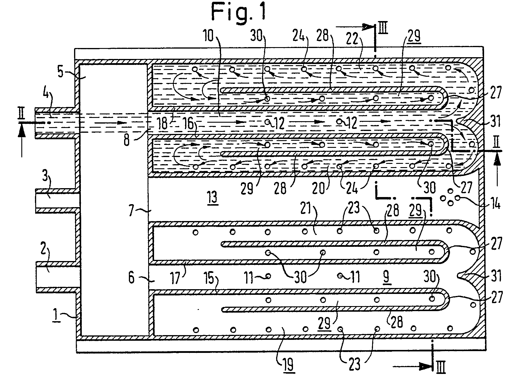
Description
Die Erfindung geht aus von einer Waschmitteleinspüleinrichtung für eine Wäschebehandlungsmaschine, die ein einseitig offenes Gehäuse und eine durch diese Öffnung bewegbare Schublade mit mehreren oben offenen Kammern für Waschmittel und Waschhilfsmittel enthält, wobei im Deckel des Gehäuses über jeder Kammer der eingeschobenen Schublade ein an eine Frischwasserdüse anschließender, mit bodenseitigen Abflußlöchern versehener Wasserführungskanal angeordnet ist, dessen erster, im wesentlichen mit der Frischwasserdüse fluchtender Abschnitt sich an seinem Ende in zwei weitere Abschnitte mit gegen die Hauptfließrichtung des Zulaufwassers gerichteter Fließrichtung verzweigt.The invention relates to a detergent dispenser for a laundry treatment machine, which contains a housing that is open on one side and a drawer that can be moved through this opening and has a plurality of compartments for detergents and washing aids that are open at the top is arranged, provided with bottom-side drainage holes, the first section, which is essentially aligned with the fresh water nozzle, branches at its end into two further sections with a flow direction directed against the main flow direction of the feed water.
Eine derartige Waschmitteleinspüleinrichtung ist aus der DE-OS 28 13 366 bekannt. In den beiden weiteren Abschnitten jedes Wasserführungskanals in der bekannten Waschmitteleinspüleinrichtung entstehen nicht klar definierbare Einzelströmungen, die zudem noch in ihrem Berührungsbereich zur Hauptströmung dieses Abschnittes eine Wirbelzone bilden. Diese Einzelströmungen formieren sich zum großen Teil zu einer Gegenströmung in diesem weiteren Abschnitt, die einen Teil der Energie in der Hauptströmung aufzehrt, so daß die Strahlenergie der aus den seitlichen Abflußlöchern austretenden, auf die Kammerwände gerichteten Wasserstrahlen teilweise nicht ausreicht, um das Waschmittel aus der zugeordneten Kammer zufriedenstellend auszuspülen.Such a detergent dispenser is known from DE-OS 28 13 366. In the two further sections of each water guide channel in the known detergent dispensing device, individual flows which are not clearly definable arise and which also form a vortex zone in their contact area with the main flow of this section. These individual flows largely form a counterflow in this further section, which consumes part of the energy in the main flow, so that the jet energy of the water jets emerging from the lateral drain holes and directed onto the chamber walls is sometimes insufficient to detergent from the Rinsing out the assigned chamber satisfactorily.
Der Erfindung liegt die Aufgabe zugrunde, bei einer eingangs beschriebenen Waschmitteleinspüleinrichtung eine gegenseitig störende Beeinflussung von Hauptströmung und Einzelströmungen so zu verbessern, daß die erforderliche Strahlenergie zum zufriedenstellenden Ausspülen des Waschmittels erhalten bleibt.The invention has for its object to improve a mutually interfering influence of the main flow and individual flows in a detergent dispenser described above so that the necessary beam energy for satisfactory rinsing of the detergent is maintained.
Erfindungsgemäß wird diese Aufgabe dadurch gelöst, daß am Ende der weiteren Kanalabschnitte je ein dritter Kanalabschnitt anschließt, dessen Strömungsrichtung im wesentlichen der des ersten Kanalabschnittes entspricht. Hierdurch können die gefürchteten Einzelströmungen im dritten Kanalabschnitt zu einer Gesamtströmung zusammengefaßt werden, die mit der Hauptströmung des weiteren Abschnitts nicht mehr in Berührung kommt. Ein hieraus herrührender Energieverzehr dieser Hauptströmung ist daher ausgeschlossen. Es ist von besonderem Vorteil, im dritten Abschnitt ebenfalls Abflußlöcher vorzusehen, damit die Strömung in der Reihenschaltung aller Kanalabschnitte erhalten bleibt und nicht etwa ein Stau verursacht wird, der wiederum zur Wirbelbildung führen würde.According to the invention, this object is achieved in that at the end of the further channel sections there is a third channel section, the flow direction of which essentially corresponds to that of the first channel section. As a result, the dreaded individual flows in the third channel section can be combined to form an overall flow which no longer comes into contact with the main flow of the further section. A resulting energy consumption of this main flow is therefore excluded. It is particularly advantageous to also provide drainage holes in the third section, so that the flow is maintained in the series connection of all the channel sections and does not cause a congestion, which in turn would lead to the formation of eddies.
Damit möglichst viel Strömungsenergie den ausspülenden Wasserstrahlen für die Kammerwände zur Verfügung steht, ist eine Weiterbildung der Erfindung besonders vorteilhaft, bei der der dritte Kanalabschnitt zwischen dem ersten und dem weiteren Kanalabschnitt gelegen ist.In order that as much flow energy as possible is available for the rinsing water jets for the chamber walls, a further development of the invention is particularly advantageous in which the third channel section is located between the first and the further channel section.
Zur Beruhigung der Strömungen in den Kanalabschnitten und zur Verminderung des Strömungsgeräusches trägt insb. eine weitere Ausbildung der Erfindung bei, in der sich zwischen dem ersten und dem dritten sowie zwischen dem dritten und dem weiteren Kanalabschnitt jeweils Trennwände befinden, die im Verzweigungsbereich am Ende des ersten Kanalabschnitts durch eine bogenförmige Wand miteinander verbunden sind, die etwa parallel zur Zweigströmung im Umlenkbereich geformt ist.A further embodiment of the invention, in particular, contributes to calming the flows in the channel sections and reducing the flow noise, in which there are partition walls between the first and the third and between the third and the further channel section, which are in the branching area at the end of the first Channel section are connected to each other by an arcuate wall which is shaped approximately parallel to the branch flow in the deflection area.
Anhand von in der Zeichnung dargestellten Ausführungsbeispielen ist die Erfindung zusammen mit weiteren vorteilhaften Merkmalen nachstehend erläutert.On the basis of exemplary embodiments shown in the drawing, the invention is explained below together with further advantageous features.
Es zeigen
- Fig. 1 einen horizontalen Schnitt durch das erfindungsgemäße Wasserführungsbauteil,
- Fig. 2 und 3 je einen Schnitt durch das erfindungsgemäße Wasserführungsbauteil entlang den in der Fig. 1 angegebenen Schnittlinien II-II und III-III sowie
- Fig. 4 eine andere Ausbildung des Verzweigungsbereiches innerhalb der in Fig. 2 angegebenen Einzelheit IV.
- 1 is a horizontal section through the water guide component according to the invention,
- 2 and 3 each show a section through the water guide component according to the invention along the section lines II-II and III-III indicated in FIG. 1 and
- Fig. 4 shows another embodiment of the branch area within the detail IV shown in Fig. 2.
Das als Deckel für das Gehäuse einer Waschmitteleinspüleinrichtung ausgebildete Wasserführungsbauteil 1 trägt an seiner Rückwand Frischwasserdüsen 2, 3 und 4. Sie münden in eine Vorkammer 5, die zum Abführen des Tropfwassers in den Waschbehälter und zur Rückflußverhinderung bereits in die Waschmitteleinspülkammer gelangten Wassers dient. In einem flachen, kastenförmigen Teil des Wasserführungsbauteiles sind gegenüber den Frischwasserdüsen 2 bis 4 Öffnungen 6, 7 und 8 angeordnet, von denen die Öffnungen 6 und 8 zu ersten Abschnitten 9 und 10 der zu den mit Waschpulver füllbaren Waschmittelkammern führenden Wasserführungskanäle ge hören. In diesen ersten Abschnitten 9 und 10 sind bereits zu den darunter liegenden Waschmittelkammern führende Abflußlöcher 11 und 12 vorgesehen. Falls es bestimmte Bedingungen ermöglichen, kann auf diese Abflußlöcher 11 und 12 auch verzichtet werden.The water guiding
Die der Frischwasserdüse 3 gegenüberliegende Öffnung 7 gehört zu einem Wasserführungskanal 13, der zur Zuführung des für die Entleerung der unter den Abflußlöchern 14 angeordneten Weichspülmittel-Kammer (nicht dargestellt) benötigten Zulaufwassers dient. Am Ende der durch die Trennwände 15 bis 18 begrenzten ersten Abschnitte 9 und 10 verzweigt sich der jeweilige Wasserführungskanal, wobei die weiteren Abschnitte als Kanalzweige 19 bis 22 parallel zum jeweils ersten Abschnitt 9 bzw. 10 liegen, vom Zulaufwasser jedoch in Gegenrichtung durchströmt werden.The opening 7 opposite the fresh water nozzle 3 belongs to a
In den äußeren Randbereichen der Kanalzweige 19 bis 22 sind in einer Reihe hintereinander angeordnete Abflußlöcher 23 bzw. 24 vorgesehen. Das in den nicht dargestellten Waschmittelkammern lagernde Waschpulver wird von den die Abflußlöcher 23 bzw. 24 durchfließenden Wasserstrahlen unterspült und vom Zulaufwasser durch die Vorkammer 5 in den Waschbehälter befördert.In the outer edge regions of the
Die im linken Teil der Fig. 3 in den Kanalabschnitten 10, 20 und 22 eingetragenen Symbole weisen entsprechend den Pfeilen in Fig. 1 und 2 auf die jeweilige Fließrichtung des Zulaufwassers hin. In Fig. 3 sind ferner durch die Seitenwände 25 und die Trennwände 26 die unter den Kanalabschnitten angeordneten Waschmittelkammern angedeutet.The symbols entered in the left-hand part of FIG. 3 in the
Die erfindungsgemäße Ausgestaltung der Wasserführungskanäle umfaßt am Ende der ersten Kanalabschnitte 9 und 10 im Verzweigungsbereich bogenförmige Wandabschnitte 27, durch welche die Trennwände 15 bis 18 im Umlenkbereich verlängert sind. An die bogenförmigen Wandabschnitte 27 schließen sich weitere, parallel zu den ersten Trennwänden 15 bis 18 liegende Trennwände 28 an. Hierdurch werden jeweils dritte Kanalabschnitte 29 gebildet, die an das jeweilige Ende der weiteren Kanalabschnitte 19 bis 22 anschließen. Am Boden dieser dritten Kanalabschnitte 29 sind ebenfalls Abflußlöcher 30 angeordnet, durch die das in die dritten Kanalabschnitte 29 gelangte Zulaufwasser in die darunter befindliche Waschmittelkammer abfließen kann. Im Verzweigungsbereich am Ende des jeweils ersten Kanalabschnittes 9 bzw. 10 ist noch ein Keil 31 angeordnet, der die Bildung von laminaren Strömungen im Umlenkbereich unterstützt.The configuration of the water guide channels according to the invention comprises, at the end of the
Die gezeigte Anordnung von in Reihe geschalteten und ineinander gefalteten Kanalabschnitten führt zu einer Beruhigung und Vergleichmäßigung der Strömungen in den einzelnen Kanalabschnitten, in denen Wirbelbildungen und Stauungen weitgehend vermieden werden. Die Rundungen innerhalb der Strömungsbereiche führen außerdem zu einer erheblichen Geräuschminderung, weil in der Strömung enthaltene Luftbläschen ebenfalls beruhigt mitschwimmen, ohne durch unstete Richtungsänderungen zu Schwingungen angeregt zu werden.The arrangement of channel sections which are connected in series and which are folded into one another leads to a calming and equalization of the currents in the individual channel sections, in which vortex formation and congestion are largely avoided. The curvatures within the flow areas also lead to a considerable reduction in noise, because air bubbles contained in the flow also swim comfortably without being stimulated to vibrate due to irregular changes in direction.
Aus Fig. 3 sind anhand der Symbole noch die Strömungsrichtungen innerhalb der dritten Kanalabschnitte 29 zu entnehmen. Daraus ist erkennbar, daß die Strömung in jedem dieser Kanalabschnitte mit der Strömung in den ersten Kanalabschnitten 9 und 10 gleichgerichtet sind.The flow directions within the
In Fig. 4 ist anhand einer Einzelheit IV aus Fig. 2 eine andere Ausgestaltung des Umlenkbereiches ersichtlich. Hierin sind die bogenförmigen Trennwand-Abschnitte 27 kegelförmig gestaltet als kegelmantelförmige Abschnitte 32. Wie sich nämlich gezeigt hat, kann die Strömungsenergie durch eine derartige Maßnahme in die Bereiche der Abflußlöcher konzentriert werden. Zur geeigneten Entformbarkeit von entsprechend gestalteten Kunststoffteilen des Wasserführungsbauteils ist im Beispiel der Fig. 4 die Trennlinie in den Bodenbereich der Wasserführungskanäle zu legen.4, another embodiment of the deflection area can be seen on the basis of a detail IV from FIG. 2. In this, the
Claims (3)
Applications Claiming Priority (2)
| Application Number | Priority Date | Filing Date | Title |
|---|---|---|---|
| DE3807431A DE3807431A1 (en) | 1988-03-07 | 1988-03-07 | DETERGENT DISCHARGE DEVICE |
| DE3807431 | 1988-03-07 |
Publications (3)
| Publication Number | Publication Date |
|---|---|
| EP0331920A2 true EP0331920A2 (en) | 1989-09-13 |
| EP0331920A3 EP0331920A3 (en) | 1990-07-11 |
| EP0331920B1 EP0331920B1 (en) | 1992-11-04 |
Family
ID=6349068
Family Applications (1)
| Application Number | Title | Priority Date | Filing Date |
|---|---|---|---|
| EP19890102226 Expired - Lifetime EP0331920B1 (en) | 1988-03-07 | 1989-02-09 | Washing product dispenser |
Country Status (4)
| Country | Link |
|---|---|
| EP (1) | EP0331920B1 (en) |
| DE (2) | DE3807431A1 (en) |
| ES (1) | ES2035380T3 (en) |
| HK (1) | HK144195A (en) |
Cited By (8)
| Publication number | Priority date | Publication date | Assignee | Title |
|---|---|---|---|---|
| EP0758031A1 (en) * | 1995-08-07 | 1997-02-12 | Bosch-Siemens HausgerÀ¤te GmbH | Washing products dispenser |
| WO2005116323A1 (en) * | 2004-04-14 | 2005-12-08 | Lg Electronics Inc. | Dispenser of detergent supply apparatus for washing machine |
| WO2010003961A1 (en) | 2008-07-07 | 2010-01-14 | Arcelik Anonim Sirketi | Detergent box flushing arrangement for a washing machine |
| US7895864B2 (en) | 2007-10-23 | 2011-03-01 | Electrolux Home Products, Inc. | Laundry additive dispenser |
| WO2012084487A1 (en) | 2010-12-24 | 2012-06-28 | Arcelik Anonim Sirketi | A washing machine comprising a cleaning agent dispenser |
| US8327672B2 (en) | 2007-12-21 | 2012-12-11 | Electrolux Home Products, Inc. | Methods and systems for water delivery in an additive dispenser |
| US9085844B2 (en) | 2007-11-13 | 2015-07-21 | Electrolux Home Products, Inc. | Sequenced water delivery in an additive dispenser |
| EP2703545A3 (en) * | 2012-08-27 | 2015-10-21 | Samsung Electronics Co., Ltd. | Washing machine having detergent supply device |
Family Cites Families (1)
| Publication number | Priority date | Publication date | Assignee | Title |
|---|---|---|---|---|
| DE2813366C2 (en) * | 1978-03-28 | 1986-04-10 | Bosch-Siemens Hausgeräte GmbH, 8000 München | Detergent dispensing device for a laundry treatment machine |
-
1988
- 1988-03-07 DE DE3807431A patent/DE3807431A1/en active Granted
-
1989
- 1989-02-09 EP EP19890102226 patent/EP0331920B1/en not_active Expired - Lifetime
- 1989-02-09 DE DE8989102226T patent/DE58902587D1/en not_active Expired - Lifetime
- 1989-02-09 ES ES198989102226T patent/ES2035380T3/en not_active Expired - Lifetime
-
1995
- 1995-09-07 HK HK144195A patent/HK144195A/en not_active IP Right Cessation
Cited By (10)
| Publication number | Priority date | Publication date | Assignee | Title |
|---|---|---|---|---|
| EP0758031A1 (en) * | 1995-08-07 | 1997-02-12 | Bosch-Siemens HausgerÀ¤te GmbH | Washing products dispenser |
| WO2005116323A1 (en) * | 2004-04-14 | 2005-12-08 | Lg Electronics Inc. | Dispenser of detergent supply apparatus for washing machine |
| US7934403B2 (en) | 2004-04-14 | 2011-05-03 | Lg Electronics Inc. | Dispenser of detergent supply apparatus for washing machine |
| US7895864B2 (en) | 2007-10-23 | 2011-03-01 | Electrolux Home Products, Inc. | Laundry additive dispenser |
| US9085844B2 (en) | 2007-11-13 | 2015-07-21 | Electrolux Home Products, Inc. | Sequenced water delivery in an additive dispenser |
| US8327672B2 (en) | 2007-12-21 | 2012-12-11 | Electrolux Home Products, Inc. | Methods and systems for water delivery in an additive dispenser |
| WO2010003961A1 (en) | 2008-07-07 | 2010-01-14 | Arcelik Anonim Sirketi | Detergent box flushing arrangement for a washing machine |
| WO2012084487A1 (en) | 2010-12-24 | 2012-06-28 | Arcelik Anonim Sirketi | A washing machine comprising a cleaning agent dispenser |
| EP2703545A3 (en) * | 2012-08-27 | 2015-10-21 | Samsung Electronics Co., Ltd. | Washing machine having detergent supply device |
| US9777424B2 (en) | 2012-08-27 | 2017-10-03 | Samsung Electronics Co., Ltd. | Washing machine having detergent supply device |
Also Published As
| Publication number | Publication date |
|---|---|
| ES2035380T3 (en) | 1993-04-16 |
| DE58902587D1 (en) | 1992-12-10 |
| DE3807431A1 (en) | 1989-09-21 |
| EP0331920B1 (en) | 1992-11-04 |
| DE3807431C2 (en) | 1990-07-26 |
| HK144195A (en) | 1995-09-15 |
| EP0331920A3 (en) | 1990-07-11 |
Similar Documents
| Publication | Publication Date | Title |
|---|---|---|
| EP0725182B1 (en) | Water supply device for household appliance with water flow | |
| EP0719884B1 (en) | Washing machine with a washing agents dispenser device | |
| DE112005000830B4 (en) | Dispenser of a detergent supply device for a washing machine | |
| EP0331920B1 (en) | Washing product dispenser | |
| DE2813366C2 (en) | Detergent dispensing device for a laundry treatment machine | |
| DE2918718C2 (en) | Detergent dispenser for a washing machine | |
| EP0318070B1 (en) | Detergent dispenser device for washing machines | |
| DE7834912U1 (en) | Detergent and additive dispenser for washing machines | |
| DE3637815A1 (en) | DEVICE FOR INFLOWING DETERGENTS FOR A WASHING MACHINE | |
| EP0238112B1 (en) | Rinsing-in device for a washing machine | |
| DE2850084C2 (en) | In-wall drain fitting with odor trap | |
| DE2253094A1 (en) | WASHING OR DISHWASHING MACHINE WITH A DISPENSER | |
| EP0330880B1 (en) | Washing product dispenser | |
| EP1230442B1 (en) | Device for electrolytically treating board-shaped workpieces, especially printed circuits | |
| DE2232020B2 (en) | Washing machine liquid distributing manifold - has intersecting inlet and outlet spigots joined by reverse flow preventing chamber | |
| EP0758031A1 (en) | Washing products dispenser | |
| CH647285A5 (en) | CYCLING WASHING MACHINE FOR DISINFECTING TREATMENT OF LAUNDRY. | |
| DE2820471C2 (en) | Method and device for the continuous wet treatment of rope-like textile goods | |
| DE2134689A1 (en) | WATER FLOW IN A WASHING MACHINE | |
| DE3831316A1 (en) | Apparatus for the water-saving washing of running material webs | |
| DE2638978A1 (en) | DEVICE FOR SEPARATING AND REMOVING WASHED-OUT DIRT PARTICLES FROM A WASHING MACHINE FOR RAIL-SHAPED MATERIAL | |
| DE949881C (en) | Wide washing machine | |
| DE430362C (en) | Flushing or spray pipe, especially for stretch yarn mercerising machines | |
| DE1915403C3 (en) | Device for the continuous washing of textile goods in web form | |
| DE8232107U1 (en) | WASHING AND ADDITIONAL DETERGENT DEVICE FOR WASHING MACHINES |
Legal Events
| Date | Code | Title | Description |
|---|---|---|---|
| PUAI | Public reference made under article 153(3) epc to a published international application that has entered the european phase |
Free format text: ORIGINAL CODE: 0009012 |
|
| AK | Designated contracting states |
Kind code of ref document: A2 Designated state(s): DE ES FR GB IT |
|
| PUAL | Search report despatched |
Free format text: ORIGINAL CODE: 0009013 |
|
| AK | Designated contracting states |
Kind code of ref document: A3 Designated state(s): DE ES FR GB IT |
|
| 17P | Request for examination filed |
Effective date: 19900723 |
|
| 17Q | First examination report despatched |
Effective date: 19911216 |
|
| GRAA | (expected) grant |
Free format text: ORIGINAL CODE: 0009210 |
|
| AK | Designated contracting states |
Kind code of ref document: B1 Designated state(s): DE ES FR GB IT |
|
| REF | Corresponds to: |
Ref document number: 58902587 Country of ref document: DE Date of ref document: 19921210 |
|
| ITF | It: translation for a ep patent filed | ||
| GBT | Gb: translation of ep patent filed (gb section 77(6)(a)/1977) |
Effective date: 19930202 |
|
| ET | Fr: translation filed | ||
| REG | Reference to a national code |
Ref country code: ES Ref legal event code: FG2A Ref document number: 2035380 Country of ref document: ES Kind code of ref document: T3 |
|
| PLBE | No opposition filed within time limit |
Free format text: ORIGINAL CODE: 0009261 |
|
| STAA | Information on the status of an ep patent application or granted ep patent |
Free format text: STATUS: NO OPPOSITION FILED WITHIN TIME LIMIT |
|
| RAP4 | Party data changed (patent owner data changed or rights of a patent transferred) |
Owner name: BOSCH-SIEMENS HAUSGERAETE GMBH |
|
| 26N | No opposition filed | ||
| PGFP | Annual fee paid to national office [announced via postgrant information from national office to epo] |
Ref country code: FR Payment date: 19960109 Year of fee payment: 8 |
|
| PGFP | Annual fee paid to national office [announced via postgrant information from national office to epo] |
Ref country code: GB Payment date: 19960202 Year of fee payment: 8 |
|
| PGFP | Annual fee paid to national office [announced via postgrant information from national office to epo] |
Ref country code: ES Payment date: 19960229 Year of fee payment: 8 |
|
| PGFP | Annual fee paid to national office [announced via postgrant information from national office to epo] |
Ref country code: DE Payment date: 19960328 Year of fee payment: 8 |
|
| PG25 | Lapsed in a contracting state [announced via postgrant information from national office to epo] |
Ref country code: GB Effective date: 19970209 |
|
| PG25 | Lapsed in a contracting state [announced via postgrant information from national office to epo] |
Ref country code: ES Free format text: LAPSE BECAUSE OF NON-PAYMENT OF DUE FEES Effective date: 19970210 |
|
| GBPC | Gb: european patent ceased through non-payment of renewal fee |
Effective date: 19970209 |
|
| PG25 | Lapsed in a contracting state [announced via postgrant information from national office to epo] |
Ref country code: FR Effective date: 19971030 |
|
| PG25 | Lapsed in a contracting state [announced via postgrant information from national office to epo] |
Ref country code: DE Effective date: 19971101 |
|
| REG | Reference to a national code |
Ref country code: FR Ref legal event code: ST |
|
| REG | Reference to a national code |
Ref country code: ES Ref legal event code: FD2A Effective date: 19990301 |
|
| PG25 | Lapsed in a contracting state [announced via postgrant information from national office to epo] |
Ref country code: IT Free format text: LAPSE BECAUSE OF NON-PAYMENT OF DUE FEES;WARNING: LAPSES OF ITALIAN PATENTS WITH EFFECTIVE DATE BEFORE 2007 MAY HAVE OCCURRED AT ANY TIME BEFORE 2007. THE CORRECT EFFECTIVE DATE MAY BE DIFFERENT FROM THE ONE RECORDED. Effective date: 20050209 |