EP0331916A2 - Elastische Hülse - Google Patents
Elastische Hülse Download PDFInfo
- Publication number
- EP0331916A2 EP0331916A2 EP89102129A EP89102129A EP0331916A2 EP 0331916 A2 EP0331916 A2 EP 0331916A2 EP 89102129 A EP89102129 A EP 89102129A EP 89102129 A EP89102129 A EP 89102129A EP 0331916 A2 EP0331916 A2 EP 0331916A2
- Authority
- EP
- European Patent Office
- Prior art keywords
- bushing
- elastomeric body
- duct
- cylindrical
- chambers
- Prior art date
- Legal status (The legal status is an assumption and is not a legal conclusion. Google has not performed a legal analysis and makes no representation as to the accuracy of the status listed.)
- Granted
Links
Images
Classifications
-
- F—MECHANICAL ENGINEERING; LIGHTING; HEATING; WEAPONS; BLASTING
- F16—ENGINEERING ELEMENTS AND UNITS; GENERAL MEASURES FOR PRODUCING AND MAINTAINING EFFECTIVE FUNCTIONING OF MACHINES OR INSTALLATIONS; THERMAL INSULATION IN GENERAL
- F16F—SPRINGS; SHOCK-ABSORBERS; MEANS FOR DAMPING VIBRATION
- F16F13/00—Units comprising springs of the non-fluid type as well as vibration-dampers, shock-absorbers, or fluid springs
- F16F13/04—Units comprising springs of the non-fluid type as well as vibration-dampers, shock-absorbers, or fluid springs comprising both a plastics spring and a damper, e.g. a friction damper
- F16F13/06—Units comprising springs of the non-fluid type as well as vibration-dampers, shock-absorbers, or fluid springs comprising both a plastics spring and a damper, e.g. a friction damper the damper being a fluid damper, e.g. the plastics spring not forming a part of the wall of the fluid chamber of the damper
- F16F13/08—Units comprising springs of the non-fluid type as well as vibration-dampers, shock-absorbers, or fluid springs comprising both a plastics spring and a damper, e.g. a friction damper the damper being a fluid damper, e.g. the plastics spring not forming a part of the wall of the fluid chamber of the damper the plastics spring forming at least a part of the wall of the fluid chamber of the damper
- F16F13/14—Units of the bushing type, i.e. loaded predominantly radially
Definitions
- the present invention concerns an elastic bushing and more particularly it refers to an elastic bushing intended to dampen hydraulically the vibrations of low frequency and great amplitude acting onto it.
- a bushing substantially comprises two concentric cylindrical elements connected together by means of an elastomeric body.
- the first cylindrical element is usually fast with a shaft passing through it,whilst the second element is secured to a permanent structure.
- the first element might be secured to a connecting rod and the second to the body of a vehicle.
- the shaft - when it is in loaded condition - has a certain degree of freedom with respect to the fixed structure to which the outermost element of the bushing is associated.
- bushings of the above described type are unable to dampen the vibrations,due to oscillating loads, of great amplitude and small frequency, to which they are subjected.
- bushings which comprise two cylindrical elements, an elastomeric body situated between said elements, and two chambers separated from each other by the elastomeric material and filled with a fluid; the two chambers are connected together by an appropriate duct.
- the two chambers are situated in opposite position with respect to the axial plane so that, in the presence of a load variation acting on the shaft, one of the chambers is subjected to compression and the fluid therein contained is compelled to pass, through the duct, into the second chamber which is in turn compelled to expand.
- the fluid is caused to flow slowly through the duct between the two chambers, with a consequent dissipation of energy, to which corresponds a dampening of the vibrations imparted to the system.
- the present invention aims to provide an elastic bushing of the hydraulic damping type, which is able to overcome the above indicated drawbacks and in particular is able to dampen vibrations of low frequency and great amplitude and to maintain low stiffening values when operating with high frequency oscillations of small amplitude, for instance of the order of tenths of millimeter.
- the present invention has the aim to provide a system which is able to prevent immediately any transmission of high frequency and small amplitude oscillations towards the permanent structure associated to the bushing.
- a further aim of the invention is to obtain good results in the elimination of transmissions of high frequency vibrations towards the permanent structure without the risk of impairing the performance and the function of the supporting elements forming the bushing and in particular without compromising in any way the effect of hydraulic damping of low frequency and great amplitude oscillations.
- the object of the present invention is an elastic bushing subjected to oscillating load, which comprises two substantially concentric hollow cylindrical elements, the innermost element being fast with a shaft or a similar member contained in its inside,and the outermost element being associated to a structure fixed with respect to the shaft, an elastomeric body being interposed between said elements for their mutual connection, said body being formed by two solid portions opposite to each other with respect to an axial plane, said solid portions being alternated to hollow spaces, closed at the two bushing's ends by two faces of the elastomeric body, said spaces and said faces forming two chambers filled with a fluid and mutually communicating through a duct able to dampen great amplitude and low frequency oscillations between said shaft and said fixed structure, the bushing being characterized in that it comprises means to absorb high frequency and small amplitude oscillations which are situated in the two chambers and are formed by two variable volume hermetically sealed cavities, each cavity being comprised between a rigid surface of the bushing and a flexible
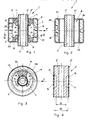
- FIGURES 1 to 3 illustrate an elastic bushing (1)which comprises two substantially concentric cylindrical elements (2),(3), the innermost of which is fast with a shaft or a similar element passing into it, whilst the outermost is associated to a structure fixed with respect to the shaft.
- the cylindrical element (2) comprises a portion (2′) of big thickness and a covering metal portion (2 ⁇ ) of smaller thickness.
- the invention may refer to a system comprising two equal bushings, in the first of which the first element is connected to a shaft associated with the motor of a vehicle and the second element is secured to a connecting rod, whilst in the second bushing the first element is connected to the body shell and the second element is fast with the connecting rod.
- An elastomeric body (4) is interposed between the two cylindrical elements (2) and (3) to connect them to each other; said body is formed by two solid portions (5),(6) which are in opposite position with respect to an axial plane and are alternated to hollow spaces (7),(8) closed at the two ends of the bushing by two faces (9),(10) of the elastomeric body.
- Faces (9) and (10) are provided on their outer surface with circular recesses (11) and (12) to impart to the elastomeric body a high elastic deformability in the presence of loads directed as indicated by arrow F in FIGURES 1 and 3.
- a fluid preferably a liquid of low viscosity, from 150 to 250 centistokes, as for instance a water-glycol solution in equal percentage.
- Chambers (13),(14) are placed into hydraulic communic ation by a duct able to dampen the great amplitude and low frequency oscillations which are directed as arrow F or in opposite sense.
- bushing (1) is characterized in that it comprises means for absorbing the high frequency and small amplitude oscillations,which are substantially formed by two variable volume cavities, hermetically sealed to contain a compressible fluid,as for example air.
- the two cavities are situated in chambers (13) and (14) and each of them is delimited between a rigid surface of the bushing and a flexible diaphragm arranged perpendicularly to the direction of the load to be absorbed.
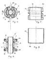
- bushing (1) is characterized in that it comprises two cavities (16),(17) (FIGS.1,3, 4), obtained by reducing the transversal dimensions of the thick portion (2′) of the first element (2) from a diameter D to a diameter d; the space originated by said reduction is tightly sealed by flexible diaphragms (18),(19) of elastomeric material, having a thickness ranging between 0.5 and 2 mm and in particular a thickness less than 1 mm.
- diaphragms (18) and (19) are associated to the covering metallic cylindrical portion (2 ⁇ ) of the first element (2) by means of a rubber/metal bonding.
- cylindrical portion is provided with appropriate openings, corresponding to the cavities of portion (2′) and tightly closed by the diaphragms.
- the two cavities (16),(17) are defined in an axial plane by a rectangular section whose longer side extends longitudinally of the bushing, at values preferably ranging between 8 mm and 25 mm. Further, each cavity (16),(17) may have a depth, measured in a radial plane, ranging between 0.5 and 3 mm.
- each cavity may correspond to that represented by an arc on the first element (2), whose angle varies from 90° to 150°.
- the bushing is characterized in that the diaphragms (18),(19) and the elastomeric body (4) build up a monolithic piece of elastomeric material.
- the outermost cylindrical element (3) is substantially formed by a rigid sleeve (FIGS.1,2,7) made for example of plastic material, containing in its inside a duct (15) to place the two chambers (13),(14) into communication.
- a rigid sleeve made for example of plastic material, containing in its inside a duct (15) to place the two chambers (13),(14) into communication.
- said damping duct (15) is formed by several coils arranged inside the wall of sleeve (20) in such a way that the input end (21) and the output end (22) are at the maximum possible distance in the direction of the bushing axial length.
- duct (15) may develop along one coil and a half, corresponding to a total angle of 540°.
- the ratio between the maximum transversal dimension and the length of the duct is preferably ranging between 0.02 and 0.06.
- the rigid sleeve (20) contains, forced in its interior, the central part of the bushing, constituted by the covering portion (2 ⁇ ) of element (2) with diaphragms (18),(19), by the elastomeric body (4), by a rigid jacket (23) associated to body (4) by rubber/metal bonding, and at last by the cylindrical portion (2′), radially innermost to element (2), already provided with cavities (16),(17) and then inserted into the covering portion (2 ⁇ ) illustrated in FIGS.5 and 6.
- the rigid jacket (23) surrounds completely both the opposite lateral faces (9),(10) and the solid portions (5),(6) of the elastomeric body and is provided with large windows along spaces (7),(8) to allow the free flow of the damping liquid between the chambers and duct (15).
- each solid portion (5),(6) of the elastomeric body (4) comprises an opening (24) of substantially triangular shape, extending for the whole length of the bushing.
- the central portion of the bushing comprising opening (24) is forced inside the cylindrical sleeve (20), precompressing the elastomeric body (4) till to close openings (24).
- the precompression of rubber, in the elastomeric body (4) cooperates in increasing the life of the elastomeric material forming the bushing, subjected to cyclic stresses.
- the sleeve comprising the central portion of the bushing is then inserted in the tubular portion (25) shown in FIG.7 and the whole is blocked by turning the end walls 26 of the tubular portions on the terminal front surfaces of the sleeve and on the front walls of jacket (23).
- the operation of the bushing is the following : - In the presence of oscillations in the direction of arrow F of FIGS.1 and 3, with low frequency values, ranging between 3 and 25 Hertz,and great amplitude values,ranging between 1 mm and 4 mm, one of chambers (13),(14) is subjected to compression and the other to expansion, with a consequent passage of liquid from one chamber to the other through duct (15).
- the liquid, passing in duct (15) whose cross section and length are appropriately selected, is subjected to a restraining action, with a consequent dissipation of energy and damping of the oscillation imparted to the system.
- the speed of oscillation is such as to prevent passage of liquid through the reduced space of the damping duct (15) and the variations in the pressure of the liquid are absorbed by the deformation of one of the two diaphragms (18),(19) and by the corresponding compression of air inside the recess closed by said diaphragms.
- the invention is able to achieve all of the intended purposes.
- the absorption means are substantially based on the use of a flexible diaphragm constituting a separate part with respect to the two lateral faces (9),(10) of the bushing. Therefore, the two faces of the elastomeric body may be given the most appropriate thickness values to bear without inconveniences the static load acting on the bushing, whilst the thickness of the diaphragm may have much smaller values, generally less than 1 mm, to assure, by a high flexibility, the absence of any stiffening of the high frequency system.
- diaphragms (18),(19) are protected against the mechanical thrust action of the liquid passing through the damping duct (15). In this way the diaphragm, not subjected to strong thrusts, remains unaffected in its lasting and cooperates in imparting a long life to the means absorbing the high frequency oscillations of the bushing.
- a duct obtained in the wall of sleeve (20) can be extended to take a substantially helical shape characterized by more than one coil, so as to create a ratio between its diameter and its length which assures the best results as regards damping.
- the damping duct is conveniently characterized by the fact that the treated liquid outflows and is conveyed towards chamber (13) or (14) in a direction tangential to the bushing.
- the system is able to dissipate energy by a tangential circulation of liquid and therefore it cannot transmit vibrations, in the direction of the load applied, towards the structure.
Landscapes
- Engineering & Computer Science (AREA)
- General Engineering & Computer Science (AREA)
- Mechanical Engineering (AREA)
- Combined Devices Of Dampers And Springs (AREA)
Applications Claiming Priority (2)
| Application Number | Priority Date | Filing Date | Title |
|---|---|---|---|
| IT1968488 | 1988-03-08 | ||
| IT8819684A IT1216017B (it) | 1988-03-08 | 1988-03-08 | Boccola elastica. |
Publications (3)
| Publication Number | Publication Date |
|---|---|
| EP0331916A2 true EP0331916A2 (de) | 1989-09-13 |
| EP0331916A3 EP0331916A3 (en) | 1990-12-05 |
| EP0331916B1 EP0331916B1 (de) | 1992-12-02 |
Family
ID=11160373
Family Applications (1)
| Application Number | Title | Priority Date | Filing Date |
|---|---|---|---|
| EP89102129A Expired EP0331916B1 (de) | 1988-03-08 | 1989-02-08 | Elastische Hülse |
Country Status (4)
| Country | Link |
|---|---|
| EP (1) | EP0331916B1 (de) |
| DE (1) | DE68903653T2 (de) |
| ES (1) | ES2037290T3 (de) |
| IT (1) | IT1216017B (de) |
Cited By (5)
| Publication number | Priority date | Publication date | Assignee | Title |
|---|---|---|---|---|
| EP0611901A1 (de) * | 1993-02-19 | 1994-08-24 | Metzeler Gimetall Ag | Hydraulisch dämpfende Lagerbuchse |
| EP1580451A1 (de) * | 2004-03-22 | 2005-09-28 | Zf Friedrichshafen Ag | Hydraulisch dämpfendes Gummilager |
| FR2904075A1 (fr) * | 2006-07-19 | 2008-01-25 | Hutchinson Sa | Support antivibratoire hydraulique, manchon interne pour un tel support et procede de fabrication d'un tel support. |
| DE102018006805A1 (de) * | 2018-08-28 | 2020-03-05 | Sumitomo Riko Company Limited | Hydroelastisches Lager |
| DE102021206281A1 (de) | 2021-06-18 | 2022-12-22 | Trumpf Lasersystems For Semiconductor Manufacturing Gmbh | Gehäuseanordnung und Dichtsystem |
Families Citing this family (1)
| Publication number | Priority date | Publication date | Assignee | Title |
|---|---|---|---|---|
| DE10351229B4 (de) * | 2003-11-03 | 2006-01-19 | Trelleborg Automotive Technical Centre Gmbh | Hydraulisch dämpfendes Lager |
Family Cites Families (2)
| Publication number | Priority date | Publication date | Assignee | Title |
|---|---|---|---|---|
| JPH0689806B2 (ja) * | 1986-01-20 | 1994-11-14 | 株式会社ブリヂストン | 防振装置 |
| GB2192968B (en) * | 1986-07-23 | 1990-03-21 | Clevite Ind Inc | Fluid filled elastomeric damping device |
-
1988
- 1988-03-08 IT IT8819684A patent/IT1216017B/it active
-
1989
- 1989-02-08 ES ES198989102129T patent/ES2037290T3/es not_active Expired - Lifetime
- 1989-02-08 EP EP89102129A patent/EP0331916B1/de not_active Expired
- 1989-02-08 DE DE8989102129T patent/DE68903653T2/de not_active Expired - Fee Related
Cited By (9)
| Publication number | Priority date | Publication date | Assignee | Title |
|---|---|---|---|---|
| EP0611901A1 (de) * | 1993-02-19 | 1994-08-24 | Metzeler Gimetall Ag | Hydraulisch dämpfende Lagerbuchse |
| DE4305173A1 (de) * | 1993-02-19 | 1994-08-25 | Metzeler Gimetall Ag | Hydraulisch dämpfende Lagerbuchse |
| US5509643A (en) * | 1993-02-19 | 1996-04-23 | Metzeler Gimetall Ag | Hydraulically damping bearing bush |
| DE4305173C2 (de) * | 1993-02-19 | 1998-03-12 | Metzeler Gimetall Ag | Hydraulisch dämpfende Lagerbuchse |
| EP1580451A1 (de) * | 2004-03-22 | 2005-09-28 | Zf Friedrichshafen Ag | Hydraulisch dämpfendes Gummilager |
| FR2904075A1 (fr) * | 2006-07-19 | 2008-01-25 | Hutchinson Sa | Support antivibratoire hydraulique, manchon interne pour un tel support et procede de fabrication d'un tel support. |
| DE102018006805A1 (de) * | 2018-08-28 | 2020-03-05 | Sumitomo Riko Company Limited | Hydroelastisches Lager |
| DE102018006805B4 (de) * | 2018-08-28 | 2020-12-17 | Sumitomo Riko Company Limited | Hydroelastisches Lager |
| DE102021206281A1 (de) | 2021-06-18 | 2022-12-22 | Trumpf Lasersystems For Semiconductor Manufacturing Gmbh | Gehäuseanordnung und Dichtsystem |
Also Published As
| Publication number | Publication date |
|---|---|
| IT8819684A0 (it) | 1988-03-08 |
| EP0331916B1 (de) | 1992-12-02 |
| DE68903653D1 (de) | 1993-01-14 |
| EP0331916A3 (en) | 1990-12-05 |
| ES2037290T3 (es) | 1993-06-16 |
| DE68903653T2 (de) | 1993-06-17 |
| IT1216017B (it) | 1990-02-22 |
Similar Documents
| Publication | Publication Date | Title |
|---|---|---|
| CA2012843C (en) | Rubber bushing | |
| US4215842A (en) | Rubber elastic engine mounts or supports with hydraulic damping | |
| US4676489A (en) | Two chamber engine mount with hydraulic damping | |
| DE58903741D1 (en) | Huelsengummifeder. | |
| JPS63145837A (ja) | 円筒型流体封入式防振支持体 | |
| US3606296A (en) | Apparatus for absorbing shocks and vibrations | |
| EP0331916A2 (de) | Elastische Hülse | |
| RU2256588C2 (ru) | Демпфер вибраций, предназначенный, в частности, для несущего винта вертолета | |
| US4667942A (en) | Pretensionable and hydraulically damped mounting element | |
| JPS62224746A (ja) | 流体封入式防振支持体 | |
| JPH09151985A (ja) | 軸 受 | |
| US5320332A (en) | Vibration damper with axial caps and diaphragm-edge areas | |
| EP4286297A3 (de) | Stossdämpfender behälter und schwingungsisolatorsystem | |
| EP0524665A2 (de) | Flüssigkeitgefüllte, elastomerische Dämpfungsvorrichtung | |
| JP2599506B2 (ja) | 液圧緩衝軸受 | |
| US4566677A (en) | Vibration damper and in particular frequency adapter for a helicopter blade | |
| JP2001295884A (ja) | 液圧緩衝式軸受 | |
| JP2909046B2 (ja) | 液圧緩衝式筒形ラバースプリング | |
| US4941649A (en) | Fluid-filled cylindrical elastic mount having means for improved durability of elastic body | |
| US5280885A (en) | Vibration isolating apparatus | |
| CN108603561B (zh) | 液压阻尼支承 | |
| JP2638353B2 (ja) | 液圧緩衝式支承 | |
| JPS62118132A (ja) | 液入り防振装置 | |
| US5322266A (en) | Hydraulic damper elastomeric body having alternating rigid and deformable wall sections | |
| GB2193553A (en) | Vibration absorbing mountings |
Legal Events
| Date | Code | Title | Description |
|---|---|---|---|
| PUAI | Public reference made under article 153(3) epc to a published international application that has entered the european phase |
Free format text: ORIGINAL CODE: 0009012 |
|
| AK | Designated contracting states |
Kind code of ref document: A2 Designated state(s): DE ES FR |
|
| PUAL | Search report despatched |
Free format text: ORIGINAL CODE: 0009013 |
|
| RHK1 | Main classification (correction) |
Ipc: F16F 13/00 |
|
| AK | Designated contracting states |
Kind code of ref document: A3 Designated state(s): DE ES FR |
|
| 17P | Request for examination filed |
Effective date: 19910114 |
|
| 17Q | First examination report despatched |
Effective date: 19910731 |
|
| GRAA | (expected) grant |
Free format text: ORIGINAL CODE: 0009210 |
|
| AK | Designated contracting states |
Kind code of ref document: B1 Designated state(s): DE ES FR |
|
| REF | Corresponds to: |
Ref document number: 68903653 Country of ref document: DE Date of ref document: 19930114 |
|
| ET | Fr: translation filed | ||
| REG | Reference to a national code |
Ref country code: ES Ref legal event code: FG2A Ref document number: 2037290 Country of ref document: ES Kind code of ref document: T3 |
|
| PLBE | No opposition filed within time limit |
Free format text: ORIGINAL CODE: 0009261 |
|
| STAA | Information on the status of an ep patent application or granted ep patent |
Free format text: STATUS: NO OPPOSITION FILED WITHIN TIME LIMIT |
|
| 26N | No opposition filed | ||
| PGFP | Annual fee paid to national office [announced via postgrant information from national office to epo] |
Ref country code: DE Payment date: 20020121 Year of fee payment: 14 |
|
| PGFP | Annual fee paid to national office [announced via postgrant information from national office to epo] |
Ref country code: ES Payment date: 20020122 Year of fee payment: 14 |
|
| PGFP | Annual fee paid to national office [announced via postgrant information from national office to epo] |
Ref country code: FR Payment date: 20020228 Year of fee payment: 14 |
|
| PG25 | Lapsed in a contracting state [announced via postgrant information from national office to epo] |
Ref country code: ES Free format text: LAPSE BECAUSE OF NON-PAYMENT OF DUE FEES Effective date: 20030210 |
|
| PG25 | Lapsed in a contracting state [announced via postgrant information from national office to epo] |
Ref country code: DE Free format text: LAPSE BECAUSE OF NON-PAYMENT OF DUE FEES Effective date: 20030902 |
|
| PG25 | Lapsed in a contracting state [announced via postgrant information from national office to epo] |
Ref country code: FR Free format text: LAPSE BECAUSE OF NON-PAYMENT OF DUE FEES Effective date: 20031031 |
|
| REG | Reference to a national code |
Ref country code: FR Ref legal event code: ST |
|
| REG | Reference to a national code |
Ref country code: ES Ref legal event code: FD2A Effective date: 20030210 |