EP0331621A2 - Contaminant shield and method of constructing same - Google Patents
Contaminant shield and method of constructing same Download PDFInfo
- Publication number
- EP0331621A2 EP0331621A2 EP89730057A EP89730057A EP0331621A2 EP 0331621 A2 EP0331621 A2 EP 0331621A2 EP 89730057 A EP89730057 A EP 89730057A EP 89730057 A EP89730057 A EP 89730057A EP 0331621 A2 EP0331621 A2 EP 0331621A2
- Authority
- EP
- European Patent Office
- Prior art keywords
- side frame
- frames
- shield
- flexible sheet
- frame members
- Prior art date
- Legal status (The legal status is an assumption and is not a legal conclusion. Google has not performed a legal analysis and makes no representation as to the accuracy of the status listed.)
- Ceased
Links
Images


Classifications
-
- E—FIXED CONSTRUCTIONS
- E04—BUILDING
- E04H—BUILDINGS OR LIKE STRUCTURES FOR PARTICULAR PURPOSES; SWIMMING OR SPLASH BATHS OR POOLS; MASTS; FENCING; TENTS OR CANOPIES, IN GENERAL
- E04H15/00—Tents or canopies, in general
- E04H15/32—Parts, components, construction details, accessories, interior equipment, specially adapted for tents, e.g. guy-line equipment, skirts, thresholds
- E04H15/64—Tent or canopy cover fastenings
- E04H15/642—Tent or canopy cover fastenings with covers held by elongated fixing members locking in longitudinal recesses of a frame
- E04H15/646—Tent or canopy cover fastenings with covers held by elongated fixing members locking in longitudinal recesses of a frame the fixing members being locked by an additional locking member
-
- B—PERFORMING OPERATIONS; TRANSPORTING
- B05—SPRAYING OR ATOMISING IN GENERAL; APPLYING FLUENT MATERIALS TO SURFACES, IN GENERAL
- B05B—SPRAYING APPARATUS; ATOMISING APPARATUS; NOZZLES
- B05B16/00—Spray booths
- B05B16/40—Construction elements specially adapted therefor, e.g. floors, walls or ceilings
Definitions
- the present invention relates to building structures.
- Such enclosures typically incorporate a skeletal framework of spaced, interconnected members to which a number of frame panels, typically rigid members made of steel or other material, are mounted.
- Building structures have also been designed for other applications, such as greenhouses, tents, etc., which use a single, flexible sheet or cover which is placed over and attached to a skelatal framework. This building structure also forms an effective containment shield or barrier surrounding a given area.
- This building structure also forms an effective containment shield or barrier surrounding a given area.
- a containment shield which can be installed at the use site in a minimum amount of time. It would also be desirable to provide a contaminant shield which has reduced manufacturing costs. It would also be desirable to provide a contaminant shield which does not require a skeletal framework to be installed at the use site for attachment of rigid frame panels thereto. Finally, it would be desirable to provide a contaminant shield which can be constructed in any configuration for widespread use in many different applications.
- the present invention is a contaminant shield and method of constructing the same.
- the contaminant shield of the present invention is formed of a plurality of identically constructed frames of the same or substantially the same configuration which are interconnected in a predetermined configuration to surround or cover a work area to prevent dust and other airborne contaminants or particles from contacting parts within the area.
- the frames are formed of a plurality of side frame members which are joined together into an integral, planar assembly having a predetermined shape.
- the side frame members surround an interior opening.
- a flexible sheet is attached to the side frame members covering the opening in the frame.
- a plurality of such frames having the same or different configuration are interconnected together to form a contaminant shield having any desired shape.
- a plurality of frame members may be interconnected to form a three-sided floor-mounted enclosure having opposed side walls joined together by a top.
- the frame members may be joined together to form an elongated planar cover having depending side walls which covers a work area in a manufacturing facility.
- the attaching means comprises each side frame member having opposed side walls joined together at one end of an integral, central portion.
- the opposite ends of the side walls are each formed with an inwardly and downwardly extending flange, with the inner faces of the flanges being spaced apart to define an aperture opening into the hollow interior of each side frame member.
- a cap member has first and second end portions, with the first end portion being complimentary shaped to the configuration of the aperture in the side frame members.
- the second end portion of the cap member has an enlarged cross section with flanges extending outward from the first end portion.
- the first end portion of a cap member is slidably inserted into the aperture in a side frame member to trap and edge of the flexible sheet between first end portion and the side frame member to securely attach the flexible sheet to the side frame member.
- Cap members are inserted into the remaining side frame members of a frame to securely attach the sheet to the frame.
- the frames are constructed at the manufacturing facility, they are shipped to the use site and arranged to form a contaminant shield having a predetermined configuration.
- the joints between adjacent side frame members of adjacent frames are sealed by a tape, for example, to provide a continuous, protrusion free surface in conjunction with the flexible sheet which provides no dust collection surfaces within or under the contaminant shield and effectively blocks the interior space enclosed or covered by the contaminant shield from airborne contaminants, such as particles, dust, water, etc.
- each of the side frame members has opposed side walls interconnected by a central portion.
- the flexible sheet is first loosely placed over one entire side of the frame covering all of the side frame members. Tension is applied to one edge of the flexible sheet while the cap member is slidably inserted into one of the side frame members trapping the edge of the flexible sheet between itself and the side frame member.
- tensioning means in the form of an elongated rod is placed over the flexible sheet drawing one edge of the sheet into the hollow interior of the side frame member. This applies tension to the sheet while the cap is inserted into that particular side frame member. Similar steps are performed with the remaining side frame members of the frame until the cap members have been emplaced within each side frame member to securely attach all of the edges of the flexible sheet to the frame.
- the contaminant shield of the present invention provides many unique advantages in constructing contaminant shields or barriers for manufacturing facilities since it minimizes installation time and has a reduced manufacturing cost.
- By constructing the individual frames at the frame manufacturing site the need for constructing and installing a skeletal frame at the use site is eliminated. This reduces installation time. Also, the advantages of mass production of identical or nearly identical frames is attained thereby reducing the overall manufacturing cost of the contaminant shield. Since the contaminant shield of the present invention finds advantageous use with conveyor lines or other elongated work areas, the contaminant shield will contain a large number of identical frames thereby enabling the economies of mass production of the identical modular frames at the frame manufacturing site to be realized.
- the contaminant shield of the present invention once installed at the use site, provides an effective barrier which prevents airborne contaminants, such as dust, particles, waterm etc., from contacting work parts or assemblies in a given area within a manufacturing facility.
- the present invention is a contaminant shield 10 which protects manufacturing parts and assemblies in a predetermined area in a manufactur ing facility from contact with airborne contaminants, such as dust particles, etc., during the manufacturing process.
- the contaminant shield 10 may be formed in any desired configuration having any predetermined length, width, height or shape depending upon the particular application to which it is applied.
- the contaminant shield 10 shown in Fig. 1 is in the form of a three-sided enclosure having opposed open ends through which parts pass.
- the contaminant shield 10 is formed of a plurality of interconnected frames 12.
- the frames 12 may have any desired shape or configuration, such as square, rectangular, triangular, trapezoidal, etc., as required for a particular application.
- the frames 12 may also have any desired dimensions. For reasons of clarity, the following description will be provided for a general overall description of the construction and use of the frame 12 shown in Fig. 1. It will be understood that this is general in nature and is not intended to limited applicant's invention to the specific configuration shown in Fig. 1.
- each frame 12 includes a plurality of side frame members 14, 16, 18 and 20 which are joined together at their ends and covered by a flexible sheet 22.
- the side frame members 14, 16, 18 and 20 are joined together, typically by welding, at their abutting ends as shown in Fig. 2.
- the side frame members thus form an opening between their innermost edges which is covered by the flexible sheet 22.
- the flexible sheet 22 is attached to the frame 12 by attaching means.
- the attaching means includes each of the side frame members 14, 16, 18 and 20 being formed with opposed side walls 24 and 26, as shown in Fig. 3, which are interconnected at one end by a central bite portion 28.
- the opposed ends of the side walls 24 and 26 terminate in inwardly and downwardly extending flanges 30 and 32, respectively, which define an aperture 33 between their opposed, facing surfaces.
- the aperture 33 opens into the hollow interior 34 within the side frame member, such as side frame member 20 shown in Fig. 3.
- the attaching means also includes a cap 36 which is removably insertable into the aperture 33 formed between the flanges 30 and 32 to trap and securely attach the edges of the flexible sheet 22 to the side frame member 20.
- the cap member 36 has a first end portion formed of spaced flanges 38 and 39 which are spaced apart so as to snugly engage the flanges 30 and 32 in the side frame member 20.
- the second end portion 40 of the cap 36 has an enlarged cross section with outwardly extending flanges 42 which overlie the edges bounding the aperture 33 to form a substantially smooth continuous surface with the flexible sheet 22.
- a plurality of generally U-shaped clamps 44 are inserted over the top of the cap members 36 and adjoining side edges of the side frame member, to hold the cap member 36 in place in the side frame member.
- One end 45 of the clamp 44 is bent toward the opposed leg to enable it to securely engage and exert a downward pressure on the cap member 36. This is important in certain applications since the flexible sheet 22 has a tendency to shrink at elevated temperatures thereby placing tension on the cap members 36 which could cause inadvertent release of the cap member 36 from the side frame member.
- a reinforcing strip 46 having a form substantially identical to that of the side frame members 14, 16, 18 and 20 is connected at opposed ends between two of the opposed side frame members, such as side frame members 16 and 20 as shown in Fig. 2.
- additional reinforcement members 48 and 50 may be connected as shown in Fig. 1 between the reinforcing strip 46 and one of the side frame members, such as side frame member 14, for further rigidity. It should be noted that the additional reinforcing members 48 and 50 need not be employed in each frame in the complete contaminant shield 10 but only at spaced locations along the length of the shield 10 where needed.
- the flexible sheet 22 is preferably formed of a flexible material which has sufficient strength to resist tearing or ripping and yet provides a non air porous barrier which prevents the passage of airborne contaminants through the contaminant shield 10.
- the flexible sheet 22 is formed of a flexible, plastic material which is clear or at least semi-transparent.
- the first step in forming the frame 12 is to interconnect a plurality of side frame members, such as side frame members 14, 16 18 and 20 in the example shown in Fig. 4, into a planar shape.
- a rectangular shape is illustrated in Fig. 4 by way of example only and includes four side frame members 14, 16, 18 and 20 which are joined together at their ends by any suitable means, such as by welding.
- the flexible sheet 22 is placed thereover and attached to the side frame members 14, 16, 18 and 20.
- attaching means is employed which comprises the interfitting cap members 36 which are slidably insertable into the hollow interior 34 of each of the side frame members as described above. It is also preferred that tension be applied to the flexible sheet 22 as each cap member 36 is inserted into its associated side frame member. Accordingly, tensioning means 52 in the form of a heavy, elongated rod is utilized. The rod 52 is placed over one edge of the flexible sheet 22 drawing the one edge of the flexible sheet 22 into the hollow interior 34 of one side frame member, such as side frame member 14. This applies tension to one end of the flexible sheet 22 as the cap member 36 is inserted into the side frame member 14. The tensioning rod 52 is then be removed from the side frame member 14.
- Another tensioning rod 52 is inserted over the flexible sheet 22 at the opposed end of the frame 12 drawing the opposite end of the flexible sheet 22 into the hollow interior 34 of the opposed side frame member 18 as shown in Fig. 4. This applies tension along one dimension of the flexible sheet 22 as the cap member 36 is inserted into the side frame member 18. The second tensioning rod 52 is then be removed from the side frame member 18.
- the cap members 36 are then inserted into the remaining side frame members 16 and 20 as tension is applied to the edges of the flexible sheet 22 overlaying each side frame member 16 and 20. Such tension can be applied by manually pulling on the outer edge of the flexible sheet 22 as each cap member 36 is inserted into the side frame member 16 and 20.
- cap clamps 44 are attached over the caps 36 to provide secure retention of the caps 36 in the side frame members.
- advantageous use of the present invention may be attained by first constructing a plurality of frames 12 as described above at a frame manufacturing facility and then shipping the frames 12 to the use site for interconnection into the completed contaminant shield 10. Since the contaminant shield 10 will usually incorporate a large number of identical frames 12, the advantages of large scale mass production may be realized since a large number of identical frames 12 may be constructed at one time at the manufacturing site.
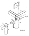
- Fig. 5 depicts the interconnection of two adjacent, vertically oriented frames, denoted in general by reference numbers 54 and 56, with a top frame 58 to form the contaminant shield 10 shown in Fig. 1.
- Each of the frames 54, 56 and 58 is substantially identically constructed as described above and shown in Figs. 2, 3 and 4.
- the vertically oriented frames 54 and 56 may be attached to an underlying support surface, such as the floor or be free standing.
- the two vertically oriented frames 54 and 56 are abutted, side-by-side and may be optionally aligned by means of an interconnecting plug 60.
- the plug 60 has a cross section so as to enable it to slidably fit within the hollow interior of the uppermost side frame members forming the frames 54 and 56 as shown in Fig. 5.
- Apertures for receiving fasteners, not shown, are formed in the interconnecting plug 60 and the central portions of the side frame members of the frames 54 and 56 to secure adjacent disposed frames 54 and 56 together.
- Interconnection is also provided for attaching one or more top, horizontally oriented frames 58 to one or more vertically oriented frames 54 and 56.
- a planar connector 62 includes apertures 64 which are alignable with corresponding apertures 66 formed in the side frame members of the vertically oriented frames 54 and 56 to receive fasteners to securely attach the horizontal frame 58 to the vertical frames 54 and 56. Additional planar connectors, not shown, may also be employed along the vertical extent of the frams 54 and 56 to securely joint adjacent side frame members together into an integral unit.
- the flexible sheet 22 be disposed on the inward side of the contaminant shield, as shown in Fig. 1, on the vertically oriented frames and on the inward or outward facing side of the horizontally oriented frames, such as frame 58. In this manner, any contaminants or particles which may enter the interior of the contaminant shield 10 will fall directly to the floor and will not adhere to the vertical or horizontal surfaces of the contaminant shield 10.
- Sealing means is also employed to completely seal the joints between abutting side frame members of adjacent positioned frames. This is shown in Fig. 5 by means of a sealing strip or tape 70 which is placed over the joint between adjacent side frame members 16 and 20 of side frames 56 and 54, respectively.
- the sealing strip 70 may be placed on the side of the joint between the flexible sheets 22 on the side frames 56 and 54 or on the opposite side as desired. This provides a continuous barrier preventing the passage of contaminants through the contaminant shield 10.
- the contaminant shield 10 of the present invention may be formed in any desired configuration depending on the particular application to which it is applied. As shown in Fig. 1, additional reinforcements, such as angularly positioned bars 72 may be attached between vertically extending side frame members and horizontal side frame members of interconnected frames to provide structural rigidity for the overall contaminant shield 10.
- top cover for water drainage.
- This requirement can be achieved by merely forming certain side frame members, such as side frame members 16, 20 in the orientation shown in Fig. 1, with a longer length than the corresponding side frame members of opposed frames. This will cause the top positioned frame to be disposed at a downward extending angle from one side of the shield 10 to the other.
- the top most frame can be formed in two or more angularly disposed sections which angle downward from a peak.
- a frame may be constructed having a slidable door, such as slidable door 74 mounted in frame 76 in Fig. 1.
- the door 74 and frame 76 are formed substantially identical to that described above with respect to frame 12 including the side frame members and overlying, attached flexible sheet 22.
- the door 74 is provided with its own frame and flexible sheet 22 and includes rollers 78 which slide within a track 80 mounted on the frame 76.
- the door 74 is sized to fit in approximately one-half of the width of the frame 76, with the remaining half having a flexible sheet and side frame assembly constructed identical to that described above for frame 12.
- the door 74 allows access to the interior of the contaminant shield 10 which may be desirable in certain applications where the length of the contaminant shield 10 is considerable.
- a plurality of doors 74 may be employed at spaced intervals along the length of the contaminant shield 10 where access is desired to the interior of the contaminant shield 10.
- An alternate configuration for the contaminant shield of the present invention is shown in Fig. 6.
- the contaminent shield 82 is in the form of a cover overlying a work surface. The cover is not attached to the floor; but, rather, is attached to the overhead building support or framework structure.
- the contaminant shield 82 is formed with two identical sections 84 and 86, each including a top, substantially horizontally oriented portion 88 and attached depending side walls 90. Both the top portion 88 and the depending side wall portions 90 are formed of a plurality of interconnected frames, formed identical to that described above with reference to frame 12.
- top portions 88 of the sections 84 and 86 are spaced apart leaving an opening 92 extending along the length of the contaminant shield 82 for passage of a conveyor 94 for conveying parts through the contaminant shield 82.
- the depending side wall portions 90 are interconnected and attached to one edge of the top sections 88 by means of angularly shaped connectors 96 which are attached to the side frame members of the top and side wall sections 88 and 90 by means of suitable fasteners, such as bolts, screws, etc.
- suitable fasteners such as bolts, screws, etc.
- the side walls 90 may be disposed at any desired angle with respect to the top portion 88.
- the top portions 88 may be disposed at a downward angle with respect to the horizontal to provide a sloped shape for the shield 82 for water drainage.
- the contaminant shield is formed of a plurality of identically constructed modular frames having a flexible sheet attached to each frame.
- the frames are interconnected at the manufacturing site to form the complete contaminent shield thereby reducing installation time since a skeletal frame work is not required and the economies of mass production of large numbers of substantially identical frames may be realized at the frame manufacturing site.
Abstract
Description
- The present invention relates to building structures.
- In manufacturing facilities, it is commonplace to protect parts and assemblies during manufacturing from airborne contaminants, such as dust, particles, water, etc., so as to prevent such contaminants from contacting the parts during assembly or during idle downtime. This is particularly important in painting, spraying and coating operations which require extreme cleanliness of the prepared surface before painting, etc., and protection of the painted surface until the paint has completely dried.
- To accomplish this, it is common to surround painting and spraying areas in a manufacturing facility with an enclosure to retain airborne paint particles within the enclosure and to prevent other contaminants from contacting the part surfaces. Such enclosures typically incorporate a skeletal framework of spaced, interconnected members to which a number of frame panels, typically rigid members made of steel or other material, are mounted.
- While the use of such a building structure is effective at containing the airborne particles within a given area or protecting parts from airborne contaminants, the cost of such a rigid panel enclosure is high especially since long distances must be covered and considerable installation time is required to install the framework in the manufacturing facility and to attach the rigid panels thereto. The high cost of previously devised enclosures has prevented their use over large portions of conveyor lines in manufacturing plants and, thus, the parts are left unprotected after painting, spraying, coating, ect., and between initial surface preparation and painting etc., and are vulnerable to dust, water and other airborne contaminants.
- Building structures have also been designed for other applications, such as greenhouses, tents, etc., which use a single, flexible sheet or cover which is placed over and attached to a skelatal framework. This building structure also forms an effective containment shield or barrier surrounding a given area. However, it has been found that it is difficult and time consuming to install a large, single piece cover to a large skeletal framework. This increases installation time and adds to overall manufacturing costs.
- Thus, it would be desirable to provide a containment shield which can be installed at the use site in a minimum amount of time. It would also be desirable to provide a contaminant shield which has reduced manufacturing costs. It would also be desirable to provide a contaminant shield which does not require a skeletal framework to be installed at the use site for attachment of rigid frame panels thereto. Finally, it would be desirable to provide a contaminant shield which can be constructed in any configuration for widespread use in many different applications.
- The present invention is a contaminant shield and method of constructing the same.
- The contaminant shield of the present invention is formed of a plurality of identically constructed frames of the same or substantially the same configuration which are interconnected in a predetermined configuration to surround or cover a work area to prevent dust and other airborne contaminants or particles from contacting parts within the area. The frames are formed of a plurality of side frame members which are joined together into an integral, planar assembly having a predetermined shape. The side frame members surround an interior opening. A flexible sheet is attached to the side frame members covering the opening in the frame.
- A plurality of such frames, having the same or different configuration are interconnected together to form a contaminant shield having any desired shape. For example, a plurality of frame members may be interconnected to form a three-sided floor-mounted enclosure having opposed side walls joined together by a top. Similarly, the frame members may be joined together to form an elongated planar cover having depending side walls which covers a work area in a manufacturing facility.
- In one embodiment, means for attaching the edges of a flexible sheet to the side frame members of a frame are provided. Preferably, the attaching means comprises each side frame member having opposed side walls joined together at one end of an integral, central portion. The opposite ends of the side walls are each formed with an inwardly and downwardly extending flange, with the inner faces of the flanges being spaced apart to define an aperture opening into the hollow interior of each side frame member. A cap member has first and second end portions, with the first end portion being complimentary shaped to the configuration of the aperture in the side frame members. The second end portion of the cap member has an enlarged cross section with flanges extending outward from the first end portion. The first end portion of a cap member is slidably inserted into the aperture in a side frame member to trap and edge of the flexible sheet between first end portion and the side frame member to securely attach the flexible sheet to the side frame member. Cap members are inserted into the remaining side frame members of a frame to securely attach the sheet to the frame.
- After the frames are constructed at the manufacturing facility, they are shipped to the use site and arranged to form a contaminant shield having a predetermined configuration. After the frames are joined together as described above to form an enclosure, shield, cover, etc., the joints between adjacent side frame members of adjacent frames are sealed by a tape, for example, to provide a continuous, protrusion free surface in conjunction with the flexible sheet which provides no dust collection surfaces within or under the contaminant shield and effectively blocks the interior space enclosed or covered by the contaminant shield from airborne contaminants, such as particles, dust, water, etc.
- In a preferred embodiment, each of the side frame members has opposed side walls interconnected by a central portion. In attaching the flexible sheet to the frame according to the method of the present invention, the flexible sheet is first loosely placed over one entire side of the frame covering all of the side frame members. Tension is applied to one edge of the flexible sheet while the cap member is slidably inserted into one of the side frame members trapping the edge of the flexible sheet between itself and the side frame member. In a preferred embodiment, tensioning means in the form of an elongated rod is placed over the flexible sheet drawing one edge of the sheet into the hollow interior of the side frame member. This applies tension to the sheet while the cap is inserted into that particular side frame member. Similar steps are performed with the remaining side frame members of the frame until the cap members have been emplaced within each side frame member to securely attach all of the edges of the flexible sheet to the frame.
- The contaminant shield of the present invention provides many unique advantages in constructing contaminant shields or barriers for manufacturing facilities since it minimizes installation time and has a reduced manufacturing cost. By constructing the individual frames at the frame manufacturing site, the need for constructing and installing a skeletal frame at the use site is eliminated. This reduces installation time. Also, the advantages of mass production of identical or nearly identical frames is attained thereby reducing the overall manufacturing cost of the contaminant shield. Since the contaminant shield of the present invention finds advantageous use with conveyor lines or other elongated work areas, the contaminant shield will contain a large number of identical frames thereby enabling the economies of mass production of the identical modular frames at the frame manufacturing site to be realized. The contaminant shield of the present invention, once installed at the use site, provides an effective barrier which prevents airborne contaminants, such as dust, particles, waterm etc., from contacting work parts or assemblies in a given area within a manufacturing facility.
- The various features, advantages and other uses of the present invention will become more apparent by referring to the following detailed description and drawing in which:
- Fig. 1 is a perspective view of a contaminant shield constructed in accordance with the teachings of one embodiment of the present invention;
- Fig. 2 is an elevational view of one of the frames employed in the contaminent shield shown in Fig. 1;
- Fig. 3 is a cross sectional view generally taken along line 3-3 in Fig. 2;
- Fig. 4 is an exploded, perspective view showing the method steps employed in constructing the frame shown in Fig. 2;
- Fig. 5 is a partial, exploded, perspective view showing the interconnection of various frames into a complete contaminant shield; and
- Fig. 6 is a perspective view of a contaminant shield constructed in accordance with the teachings of another embodiment of the present invention.
- Throughout the following description and drawing, an identical reference number is used to refer to the same component shown in multiple figures of the drawing.
- As shown in general in Fig. 1, the present invention is a contaminant shield 10 which protects manufacturing parts and assemblies in a predetermined area in a manufactur ing facility from contact with airborne contaminants, such as dust particles, etc., during the manufacturing process.
- As shown in Fig. 1 and in greater detail in Figs. 2-5, the contaminant shield 10 may be formed in any desired configuration having any predetermined length, width, height or shape depending upon the particular application to which it is applied. By way of example only, the contaminant shield 10 shown in Fig. 1 is in the form of a three-sided enclosure having opposed open ends through which parts pass.
- The contaminant shield 10 is formed of a plurality of
interconnected frames 12. Theframes 12 may have any desired shape or configuration, such as square, rectangular, triangular, trapezoidal, etc., as required for a particular application. Theframes 12 may also have any desired dimensions. For reasons of clarity, the following description will be provided for a general overall description of the construction and use of theframe 12 shown in Fig. 1. It will be understood that this is general in nature and is not intended to limited applicant's invention to the specific configuration shown in Fig. 1. - As shown in Figs. 2,3, and 4, each
frame 12 includes a plurality ofside frame members flexible sheet 22. Theside frame members flexible sheet 22. - In a preferred embodiment, the
flexible sheet 22 is attached to theframe 12 by attaching means. The attaching means includes each of theside frame members opposed side walls central bite portion 28. The opposed ends of theside walls flanges hollow interior 34 within the side frame member, such asside frame member 20 shown in Fig. 3. - The attaching means also includes a
cap 36 which is removably insertable into the aperture 33 formed between theflanges flexible sheet 22 to theside frame member 20. As shown in detail in Fig. 3, thecap member 36 has a first end portion formed of spacedflanges flanges side frame member 20. Thesecond end portion 40 of thecap 36 has an enlarged cross section with outwardly extendingflanges 42 which overlie the edges bounding the aperture 33 to form a substantially smooth continuous surface with theflexible sheet 22. - As shown in Figs. 2 and 4, a plurality of generally U-shaped clamps 44 are inserted over the top of the
cap members 36 and adjoining side edges of the side frame member, to hold thecap member 36 in place in the side frame member. One end 45 of theclamp 44 is bent toward the opposed leg to enable it to securely engage and exert a downward pressure on thecap member 36. This is important in certain applications since theflexible sheet 22 has a tendency to shrink at elevated temperatures thereby placing tension on thecap members 36 which could cause inadvertent release of thecap member 36 from the side frame member. - Various reinforcing members may also be employed to increase the rigidity and structural strength of the
frame 12. As shown in Figs. 1 and 2, a reinforcingstrip 46 having a form substantially identical to that of theside frame members side frame members additional reinforcement members strip 46 and one of the side frame members, such asside frame member 14, for further rigidity. It should be noted that the additional reinforcingmembers - The
flexible sheet 22 is preferably formed of a flexible material which has sufficient strength to resist tearing or ripping and yet provides a non air porous barrier which prevents the passage of airborne contaminants through the contaminant shield 10. Preferably, theflexible sheet 22 is formed of a flexible, plastic material which is clear or at least semi-transparent. - Referring now to Fig. 4, there is illustrated the sequential method steps employed in forming one of the
frames 12 of the present invention. The first step in forming theframe 12 is to interconnect a plurality of side frame members, such asside frame members side frame members side frame members flexible sheet 22 is placed thereover and attached to theside frame members - In a preferred embodiment, attaching means is employed which comprises the
interfitting cap members 36 which are slidably insertable into thehollow interior 34 of each of the side frame members as described above. It is also preferred that tension be applied to theflexible sheet 22 as eachcap member 36 is inserted into its associated side frame member. Accordingly, tensioning means 52 in the form of a heavy, elongated rod is utilized. Therod 52 is placed over one edge of theflexible sheet 22 drawing the one edge of theflexible sheet 22 into thehollow interior 34 of one side frame member, such asside frame member 14. This applies tension to one end of theflexible sheet 22 as thecap member 36 is inserted into theside frame member 14. Thetensioning rod 52 is then be removed from theside frame member 14. - Another
tensioning rod 52 is inserted over theflexible sheet 22 at the opposed end of theframe 12 drawing the opposite end of theflexible sheet 22 into thehollow interior 34 of the opposedside frame member 18 as shown in Fig. 4. This applies tension along one dimension of theflexible sheet 22 as thecap member 36 is inserted into theside frame member 18. Thesecond tensioning rod 52 is then be removed from theside frame member 18. - The
cap members 36 are then inserted into the remainingside frame members flexible sheet 22 overlaying eachside frame member flexible sheet 22 as eachcap member 36 is inserted into theside frame member - Finally, the cap clamps 44 are attached over the
caps 36 to provide secure retention of thecaps 36 in the side frame members. - As noted above, advantageous use of the present invention may be attained by first constructing a plurality of
frames 12 as described above at a frame manufacturing facility and then shipping theframes 12 to the use site for interconnection into the completed contaminant shield 10. Since the contaminant shield 10 will usually incorporate a large number ofidentical frames 12, the advantages of large scale mass production may be realized since a large number ofidentical frames 12 may be constructed at one time at the manufacturing site. - The interconnection of the
frames 12 into the complete contaminant shield 10 is illustrated in greater detail in Fig. 5 which depicts the interconnection of two adjacent, vertically oriented frames, denoted in general byreference numbers 54 and 56, with a top frame 58 to form the contaminant shield 10 shown in Fig. 1. - Each of the
frames 54, 56 and 58 is substantially identically constructed as described above and shown in Figs. 2, 3 and 4. The vertically orientedframes 54 and 56 may be attached to an underlying support surface, such as the floor or be free standing. The two vertically orientedframes 54 and 56 are abutted, side-by-side and may be optionally aligned by means of an interconnectingplug 60. Theplug 60 has a cross section so as to enable it to slidably fit within the hollow interior of the uppermost side frame members forming theframes 54 and 56 as shown in Fig. 5. Apertures for receiving fasteners, not shown, are formed in the interconnectingplug 60 and the central portions of the side frame members of theframes 54 and 56 to secure adjacentdisposed frames 54 and 56 together. - Interconnection is also provided for attaching one or more top, horizontally oriented frames 58 to one or more vertically oriented
frames 54 and 56. Aplanar connector 62 includesapertures 64 which are alignable withcorresponding apertures 66 formed in the side frame members of the vertically orientedframes 54 and 56 to receive fasteners to securely attach the horizontal frame 58 to thevertical frames 54 and 56. Additional planar connectors, not shown, may also be employed along the vertical extent of theframs 54 and 56 to securely joint adjacent side frame members together into an integral unit. - In order to provide a contaminant free barrier as well as a shield having no dust or contaminant collection surfaces, it is preferred that the
flexible sheet 22 be disposed on the inward side of the contaminant shield, as shown in Fig. 1, on the vertically oriented frames and on the inward or outward facing side of the horizontally oriented frames, such as frame 58. In this manner, any contaminants or particles which may enter the interior of the contaminant shield 10 will fall directly to the floor and will not adhere to the vertical or horizontal surfaces of the contaminant shield 10. - Sealing means is also employed to completely seal the joints between abutting side frame members of adjacent positioned frames. This is shown in Fig. 5 by means of a sealing strip or
tape 70 which is placed over the joint between adjacentside frame members strip 70 may be placed on the side of the joint between theflexible sheets 22 on the side frames 56 and 54 or on the opposite side as desired. This provides a continuous barrier preventing the passage of contaminants through the contaminant shield 10. - As noted above, the contaminant shield 10 of the present invention may be formed in any desired configuration depending on the particular application to which it is applied. As shown in Fig. 1, additional reinforcements, such as angularly positioned bars 72 may be attached between vertically extending side frame members and horizontal side frame members of interconnected frames to provide structural rigidity for the overall contaminant shield 10.
- Also, certain applications require a sloped or angled top cover for water drainage. This requirement can be achieved by merely forming certain side frame members, such as
side frame members - Futher, a frame may be constructed having a slidable door, such as slidable door 74 mounted in frame 76 in Fig. 1. The door 74 and frame 76 are formed substantially identical to that described above with respect to frame 12 including the side frame members and overlying, attached
flexible sheet 22. However, the door 74 is provided with its own frame andflexible sheet 22 and includesrollers 78 which slide within atrack 80 mounted on the frame 76. The door 74 is sized to fit in approximately one-half of the width of the frame 76, with the remaining half having a flexible sheet and side frame assembly constructed identical to that described above forframe 12. The door 74 allows access to the interior of the contaminant shield 10 which may be desirable in certain applications where the length of the contaminant shield 10 is considerable. It should be noted that a plurality of doors 74 may be employed at spaced intervals along the length of the contaminant shield 10 where access is desired to the interior of the contaminant shield 10. An alternate configuration for the contaminant shield of the present invention is shown in Fig. 6. In Fig. 6, thecontaminent shield 82 is in the form of a cover overlying a work surface. The cover is not attached to the floor; but, rather, is attached to the overhead building support or framework structure. Thecontaminant shield 82 is formed with two identical sections 84 and 86, each including a top, substantially horizontally orientedportion 88 and attached depending side walls 90. Both thetop portion 88 and the depending side wall portions 90 are formed of a plurality of interconnected frames, formed identical to that described above with reference to frame 12. - It should be noted that the
top portions 88 of the sections 84 and 86 are spaced apart leaving anopening 92 extending along the length of thecontaminant shield 82 for passage of aconveyor 94 for conveying parts through thecontaminant shield 82. The depending side wall portions 90 are interconnected and attached to one edge of thetop sections 88 by means of angularly shapedconnectors 96 which are attached to the side frame members of the top andside wall sections 88 and 90 by means of suitable fasteners, such as bolts, screws, etc. It should be noted that the side walls 90 may be disposed at any desired angle with respect to thetop portion 88. Also, thetop portions 88 may be disposed at a downward angle with respect to the horizontal to provide a sloped shape for theshield 82 for water drainage. - In summary, there has been disclosed a unique contaminant shield and method for constructing the same which prevents airborne contaminants, such as dust particles, water, etc., from contacting and accumulating on the surfaces of parts and assemblies in a manufacturing facility. The contaminant shield is formed of a plurality of identically constructed modular frames having a flexible sheet attached to each frame. The frames are interconnected at the manufacturing site to form the complete contaminent shield thereby reducing installation time since a skeletal frame work is not required and the economies of mass production of large numbers of substantially identical frames may be realized at the frame manufacturing site.
Claims (15)
joining a plurality of elongated, planar side frame members into a frame;
attaching a flexible sheet to one side of the frame;
abutting certain side frame members of a plurality of frames into a predetermined configuration; and
joining abutting side frame members together.
sealing the joint between abutting side frame members of a plurality of frames to form a continuous contaminant barrier in conjunction with the flexible sheet on each frame.
placing the edges of the flexible sheet over the side frame members, each of the side frame members being formed with opposed side walls interconnected by a central portion, with inwardly and downwardly extending, spaced flanges formed on the opposite ends of the side walls forming an aperture opening into the hollow interior of the side frame members;
inserting a cap having a first end portion formed complimentary to the aperture in the side frame members and a second enlarged portion having flanges extending outward from the first end portion to overlay the flanges in the side frame member into the aperture in the side frame member trapping the edge of the flexible sheet between the first end portion of the cap member and the side frame to securely attach the flexible sheet to the side frame; and
repeating the insertion of a cap member into a side frame member for each of the remaining side members of the frame.
tensioning the sheet as the cap member is inserted into a side frame member trapping the flexible sheet between the cap member and the side frame member.
inserting tensioning means overlaying one edge of the sheet into the interior of certain of the side frame members to dispose one edge of the sheet in the interior of the side frame member and to apply tension to the sheet as the cap member is inserted into the side frame member.
a plurality of like frames, each frame comprising:
a plurality of side frame members joined into a frame having a predetermined shape;
a flexible sheet; and
means for attaching the edges of the flexible sheet to one side of the frame; and
means for joining a plurality of like frames with attached sheets into a complete contaminant shield of predetermined shape.
sealing means for sealing the joint between adjacent, abutting side frame members of adjacently disposed frames to form a continuous, contaminant barrier in conjunction with the flexible sheets attached to adjacent frames.
each of the side frame members being formed with spaced side walls interconnected at one end by a central portion and inwardly and downwardly extending flanges formed at the opposite end of each side wall having spaced opposed surfaces forming an aperture opening into the hollow interior of the side frame member; and
a cap member having a first portion shaped complimentary to the aperture in the side frame member and an enlarged second portion having flanges extending outward beyond the first end portion for trapping the edge of the flexible sheet in the aperture in the side frame as the cap member is inserted over the flexible sheet into the aperture in the side frame.
the frames forming the top wall of the shield are disposed facing outward from the shield to form a flush exterior surface.
the height of the frames forming one side wall is larger than the height of the frames forming the opposed side wall such that the top wall extends to an angle between the side walls.
the sealing means comprises a strip joined to abutting side frame members and spanning the joint between the abutting side frame members.
Applications Claiming Priority (2)
| Application Number | Priority Date | Filing Date | Title |
|---|---|---|---|
| US164220 | 1988-03-04 | ||
| US07/164,220 US4860778A (en) | 1988-03-04 | 1988-03-04 | Contaminant shield and method of constructing same |
Publications (2)
| Publication Number | Publication Date |
|---|---|
| EP0331621A2 true EP0331621A2 (en) | 1989-09-06 |
| EP0331621A3 EP0331621A3 (en) | 1990-05-16 |
Family
ID=22593500
Family Applications (1)
| Application Number | Title | Priority Date | Filing Date |
|---|---|---|---|
| EP89730057A Ceased EP0331621A3 (en) | 1988-03-04 | 1989-03-02 | Contaminant shield and method of constructing same |
Country Status (2)
| Country | Link |
|---|---|
| US (1) | US4860778A (en) |
| EP (1) | EP0331621A3 (en) |
Cited By (8)
| Publication number | Priority date | Publication date | Assignee | Title |
|---|---|---|---|---|
| DE4227889A1 (en) * | 1992-08-22 | 1994-02-24 | Goetz Metall Anlagen | Paint booth |
| WO1996025238A1 (en) * | 1995-02-14 | 1996-08-22 | Balak Coatings N.V. | Powder spraying booth |
| DE29708225U1 (en) * | 1996-09-17 | 1997-06-26 | Laflow Reinraumtechnik Gmbh & | Clean room tent |
| FR2750621A1 (en) * | 1996-07-03 | 1998-01-09 | Costa Sa | Semi-rigid dust free paint cubicle |
| DE19739644A1 (en) * | 1997-09-10 | 1999-03-25 | Eisenmann Kg Maschbau | Wall for the cabin of a paint shop |
| EP0941771A3 (en) * | 1998-03-13 | 2000-06-07 | Dürr Systems GmbH | Wall segment for a cabin construction |
| EP0894540A3 (en) * | 1997-07-28 | 2001-03-07 | Haden, Inc., | Contaminant shield from aluminium extrusion |
| DE202009005832U1 (en) | 2009-04-18 | 2009-07-02 | Sabura International Gmbh | cabin |
Families Citing this family (16)
| Publication number | Priority date | Publication date | Assignee | Title |
|---|---|---|---|---|
| US5181354A (en) * | 1991-03-05 | 1993-01-26 | Tri-Mark Metal Corporation | Barrier panel |
| US5172526A (en) * | 1991-05-02 | 1992-12-22 | Morgan Melvin L | Shelter |
| US5224306A (en) * | 1991-11-13 | 1993-07-06 | Gallagher-Kaiser Corporation | Enclosure assembly |
| US5242004A (en) * | 1992-01-21 | 1993-09-07 | Johann Stilling | Awning structures |
| US5383312A (en) * | 1993-11-08 | 1995-01-24 | Haden Schweitzer Corporation | Contaminant shield |
| US5906078A (en) * | 1996-10-09 | 1999-05-25 | Gallagher-Kaiser Corporation | Retaining strip for sheet covered enclosures |
| US5848500A (en) * | 1997-01-07 | 1998-12-15 | Eastman Kodak Company | Light-tight enclosure and joint connectors for enclosure framework |
| US6192643B1 (en) * | 1999-01-14 | 2001-02-27 | Yigel Zadok | Modular pool enclosure system having aesthetic appeal |
| US6758014B2 (en) * | 2002-10-15 | 2004-07-06 | Tai-Shan Chen | Trellis structure |
| US20060000177A1 (en) * | 2004-06-14 | 2006-01-05 | Salzano Claudio V | Frame assembly and environmental enclosure |
| US20070220846A1 (en) * | 2006-03-24 | 2007-09-27 | Jeremy Ray | Enclosed portable work station |
| US20100032107A1 (en) * | 2008-07-03 | 2010-02-11 | Gallagher-Kaiser Corporation | Enclosure assembly |
| CN102094228B (en) * | 2009-12-09 | 2013-09-18 | 鸿富锦精密工业(深圳)有限公司 | Anodization production line |
| US9546486B2 (en) * | 2010-11-09 | 2017-01-17 | Tara L. Desjardins | Patio extrusion beam cap |
| DE202013100926U1 (en) * | 2013-03-04 | 2014-06-12 | Raico Bautechnik Gmbh | Steel support profile for supporting structures of facades and conservatories |
| WO2024036059A2 (en) * | 2022-08-10 | 2024-02-15 | Sensei Ag Holdings, Inc. | Pretensioned greenhouse panels |
Citations (3)
| Publication number | Priority date | Publication date | Assignee | Title |
|---|---|---|---|---|
| FR2157101A1 (en) * | 1971-10-18 | 1973-06-01 | Sinety Roger De | |
| EP0006844A1 (en) * | 1978-07-07 | 1980-01-23 | Feilhauer, Ingrid | Profiled clamp for foils or sheets and frame composed of such clamps |
| WO1984002287A1 (en) * | 1982-12-09 | 1984-06-21 | Rovac Ab | Arrangement enabling the treatment and/or manufacture of objects to take place inside a chamber |
Family Cites Families (31)
| Publication number | Priority date | Publication date | Assignee | Title |
|---|---|---|---|---|
| US2711181A (en) * | 1951-05-01 | 1955-06-21 | Spheric Structures Inc | Spherical structure |
| US2905281A (en) * | 1951-08-02 | 1959-09-22 | Alumatic Corp Of America | Porch or garden house enclosure |
| US2757677A (en) * | 1952-07-22 | 1956-08-07 | Bernard L Denn | Tent frame |
| US2828757A (en) * | 1956-07-17 | 1958-04-01 | Tepee Trail Inc | Collapsible passageway |
| US3004542A (en) * | 1959-10-01 | 1961-10-17 | Allen M Moody | Frame type quadranted shelter |
| FR1338345A (en) * | 1962-05-24 | 1963-09-27 | Lightweight Campaign Tent Set | |
| US3343324A (en) * | 1964-03-24 | 1967-09-26 | Gordon William | Underwater structural unit |
| GB1166489A (en) * | 1965-11-04 | 1969-10-08 | Yoshimi Yazaki | Building Constructions Capable of being Readily Fabricated or Dismantled |
| GB1176643A (en) * | 1966-01-14 | 1970-01-07 | Wigginloft Ltd | Improvements relating to Methods of Tensioning, or Fixing and Tensioning, Flexible Sheets in Peripheral Framing and to Panels and Portable Building Structures Incorporating the Tensioned Sheets or Panels. |
| US3375831A (en) * | 1966-07-13 | 1968-04-02 | Serbus George | Plastic covering structure |
| US3660952A (en) * | 1970-02-19 | 1972-05-09 | Pryce Wilson | Prefabricated modular building |
| US3788335A (en) * | 1971-11-09 | 1974-01-29 | Space Age Ind Inc | Anchor means for portable building structure |
| US4146997A (en) * | 1973-09-20 | 1979-04-03 | M. Ted Raptes | Domical-type structure |
| US3909994A (en) * | 1974-04-03 | 1975-10-07 | Temcor | Dome construction |
| US4091584A (en) * | 1977-02-09 | 1978-05-30 | Brown Ralph E | Small building structure |
| US4121604A (en) * | 1977-06-17 | 1978-10-24 | Irvin Industries Inc. | Rigid frame structure with tensioned membrane cladding |
| FR2400607A1 (en) * | 1977-07-25 | 1979-03-16 | Marshall Woolfe Kaye | Double glazing for existing windows - has cover frame which clips onto glue fixed base frame to secure second pane |
| US4189880A (en) * | 1978-06-16 | 1980-02-26 | Gene Ballin | Combination mounting frame and film for a window |
| US4231289A (en) * | 1979-01-26 | 1980-11-04 | Alain Domicent | Painting booth |
| US4274234A (en) * | 1979-02-22 | 1981-06-23 | Hartwig-Hartoglass, Inc. | Double-wall greenhouse with flexible film walls |
| US4261144A (en) * | 1979-07-05 | 1981-04-14 | Rhw, Inc. | Vertical corner post for screened-in room structure |
| NL7907433A (en) * | 1979-10-08 | 1981-04-10 | Philips Nv | CABLE FITTED WITH OPTICAL FIBERS. |
| US4347690A (en) * | 1979-12-19 | 1982-09-07 | Wallace Jr Brenton G | Skeletal framework structure and junction for use therein |
| US4404980A (en) * | 1980-09-30 | 1983-09-20 | James Nemec | Arched support structure with cover |
| US4381629A (en) * | 1980-11-28 | 1983-05-03 | Ahn Min H | Greenhouse |
| US4453585A (en) * | 1981-07-10 | 1984-06-12 | Ruggeberg Sr Bruno | Window thermal insulation device |
| US4649947A (en) * | 1983-08-19 | 1987-03-17 | Brunswick Corporation | Expandable soft side shelter |
| US4566236A (en) * | 1984-02-09 | 1986-01-28 | Pound John A | Greenhouse structure element |
| US4696132A (en) * | 1985-04-22 | 1987-09-29 | Leblanc J T | Foldable shelter system and method of construction |
| US4665670A (en) * | 1985-07-19 | 1987-05-19 | Den Burg Wouter M Van | Two-piece lock for securing polymeric sheeting over greenhouses |
| US4769962A (en) * | 1986-06-23 | 1988-09-13 | Venderbush Industrial Corporation | Controlled environment enclosure |
-
1988
- 1988-03-04 US US07/164,220 patent/US4860778A/en not_active Expired - Fee Related
-
1989
- 1989-03-02 EP EP89730057A patent/EP0331621A3/en not_active Ceased
Patent Citations (3)
| Publication number | Priority date | Publication date | Assignee | Title |
|---|---|---|---|---|
| FR2157101A1 (en) * | 1971-10-18 | 1973-06-01 | Sinety Roger De | |
| EP0006844A1 (en) * | 1978-07-07 | 1980-01-23 | Feilhauer, Ingrid | Profiled clamp for foils or sheets and frame composed of such clamps |
| WO1984002287A1 (en) * | 1982-12-09 | 1984-06-21 | Rovac Ab | Arrangement enabling the treatment and/or manufacture of objects to take place inside a chamber |
Cited By (10)
| Publication number | Priority date | Publication date | Assignee | Title |
|---|---|---|---|---|
| DE4227889A1 (en) * | 1992-08-22 | 1994-02-24 | Goetz Metall Anlagen | Paint booth |
| WO1996025238A1 (en) * | 1995-02-14 | 1996-08-22 | Balak Coatings N.V. | Powder spraying booth |
| NL9500266A (en) * | 1995-02-14 | 1996-09-02 | Balak Coatings N V | Powder spray booth. |
| FR2750621A1 (en) * | 1996-07-03 | 1998-01-09 | Costa Sa | Semi-rigid dust free paint cubicle |
| DE29708225U1 (en) * | 1996-09-17 | 1997-06-26 | Laflow Reinraumtechnik Gmbh & | Clean room tent |
| EP0894540A3 (en) * | 1997-07-28 | 2001-03-07 | Haden, Inc., | Contaminant shield from aluminium extrusion |
| DE19739644A1 (en) * | 1997-09-10 | 1999-03-25 | Eisenmann Kg Maschbau | Wall for the cabin of a paint shop |
| DE19739644C2 (en) * | 1997-09-10 | 1999-08-05 | Eisenmann Kg Maschbau | Wall for the cabin of a paint shop |
| EP0941771A3 (en) * | 1998-03-13 | 2000-06-07 | Dürr Systems GmbH | Wall segment for a cabin construction |
| DE202009005832U1 (en) | 2009-04-18 | 2009-07-02 | Sabura International Gmbh | cabin |
Also Published As
| Publication number | Publication date |
|---|---|
| EP0331621A3 (en) | 1990-05-16 |
| US4860778A (en) | 1989-08-29 |
Similar Documents
| Publication | Publication Date | Title |
|---|---|---|
| US4860778A (en) | Contaminant shield and method of constructing same | |
| CA2076941C (en) | Enclosure assembly | |
| US5167474A (en) | Form for making a permanent concrete mine stopping | |
| EP0894540A2 (en) | Contaminant shield from aluminium extrusion | |
| US4769962A (en) | Controlled environment enclosure | |
| US4640075A (en) | Contaminant sealing system and method | |
| US20060000177A1 (en) | Frame assembly and environmental enclosure | |
| DE19509127A1 (en) | Decorative elements for suspended ceilings | |
| US20030014926A1 (en) | Pitch pocket | |
| CN1125225C (en) | Building method of pipeline house | |
| EP0434384A1 (en) | Portable room | |
| JP3098075B2 (en) | Method of forming tight frame for fire protection compartment | |
| JPH06495Y2 (en) | Frame device for frame in skylight | |
| GB2092636A (en) | Enclosure | |
| JPH08184179A (en) | Side surface protecting wall assembling method for suspended scaffold and side surface protecting panel therefor | |
| EP1159500A1 (en) | Device at fence system to connect wire netting and profile moulding | |
| AU2020277259B2 (en) | A Waterproofing Cover | |
| EP2276131B1 (en) | Protective casing | |
| DE4316041A1 (en) | Fire stop made up of panel-like individual elements | |
| JPH0558093B2 (en) | ||
| JPH10252950A (en) | Piping device, and its cover holder | |
| JPS636351Y2 (en) | ||
| JP3439958B2 (en) | Floor structure of nuclear facilities and construction method | |
| EP0375277A2 (en) | Building system | |
| JPS61233143A (en) | Method for assembling curtain wall |
Legal Events
| Date | Code | Title | Description |
|---|---|---|---|
| PUAI | Public reference made under article 153(3) epc to a published international application that has entered the european phase |
Free format text: ORIGINAL CODE: 0009012 |
|
| AK | Designated contracting states |
Kind code of ref document: A2 Designated state(s): BE DE ES FR GB IT SE |
|
| PUAL | Search report despatched |
Free format text: ORIGINAL CODE: 0009013 |
|
| AK | Designated contracting states |
Kind code of ref document: A3 Designated state(s): BE DE ES FR GB IT SE |
|
| 17P | Request for examination filed |
Effective date: 19900820 |
|
| DIN1 | Information on inventor provided before grant (deleted) | ||
| RAP1 | Party data changed (applicant data changed or rights of an application transferred) |
Owner name: POHL, RONALD R. |
|
| 17Q | First examination report despatched |
Effective date: 19911206 |
|
| STAA | Information on the status of an ep patent application or granted ep patent |
Free format text: STATUS: THE APPLICATION HAS BEEN REFUSED |
|
| 18R | Application refused |
Effective date: 19930329 |