EP0434384A1 - Portable room - Google Patents
Portable room Download PDFInfo
- Publication number
- EP0434384A1 EP0434384A1 EP90313897A EP90313897A EP0434384A1 EP 0434384 A1 EP0434384 A1 EP 0434384A1 EP 90313897 A EP90313897 A EP 90313897A EP 90313897 A EP90313897 A EP 90313897A EP 0434384 A1 EP0434384 A1 EP 0434384A1
- Authority
- EP
- European Patent Office
- Prior art keywords
- panel
- room according
- portable room
- portable
- members
- Prior art date
- Legal status (The legal status is an assumption and is not a legal conclusion. Google has not performed a legal analysis and makes no representation as to the accuracy of the status listed.)
- Withdrawn
Links
- 239000000463 material Substances 0.000 claims abstract description 31
- 238000007789 sealing Methods 0.000 claims abstract description 14
- 229910052751 metal Inorganic materials 0.000 claims description 8
- 239000002184 metal Substances 0.000 claims description 8
- 229920003023 plastic Polymers 0.000 claims description 8
- 239000004033 plastic Substances 0.000 claims description 8
- 150000001875 compounds Chemical class 0.000 claims description 2
- 238000010276 construction Methods 0.000 description 6
- 229910000831 Steel Inorganic materials 0.000 description 4
- 239000010959 steel Substances 0.000 description 4
- 230000004888 barrier function Effects 0.000 description 3
- 229920000915 polyvinyl chloride Polymers 0.000 description 3
- 239000004800 polyvinyl chloride Substances 0.000 description 3
- 235000001674 Agaricus brunnescens Nutrition 0.000 description 2
- 235000004443 Ricinus communis Nutrition 0.000 description 2
- 240000000528 Ricinus communis Species 0.000 description 2
- 239000004411 aluminium Substances 0.000 description 2
- 229910052782 aluminium Inorganic materials 0.000 description 2
- XAGFODPZIPBFFR-UHFFFAOYSA-N aluminium Chemical compound [Al] XAGFODPZIPBFFR-UHFFFAOYSA-N 0.000 description 2
- 238000007796 conventional method Methods 0.000 description 2
- 238000004519 manufacturing process Methods 0.000 description 2
- 238000000034 method Methods 0.000 description 2
- -1 polyethylene Polymers 0.000 description 2
- 238000003860 storage Methods 0.000 description 2
- 239000004925 Acrylic resin Substances 0.000 description 1
- 241000238631 Hexapoda Species 0.000 description 1
- 241001465754 Metazoa Species 0.000 description 1
- 239000004698 Polyethylene Substances 0.000 description 1
- 239000004743 Polypropylene Substances 0.000 description 1
- 238000003975 animal breeding Methods 0.000 description 1
- 238000006243 chemical reaction Methods 0.000 description 1
- 238000004140 cleaning Methods 0.000 description 1
- 238000004320 controlled atmosphere Methods 0.000 description 1
- 230000007797 corrosion Effects 0.000 description 1
- 238000005260 corrosion Methods 0.000 description 1
- 238000005520 cutting process Methods 0.000 description 1
- 230000000694 effects Effects 0.000 description 1
- 238000004049 embossing Methods 0.000 description 1
- 238000011065 in-situ storage Methods 0.000 description 1
- 238000004377 microelectronic Methods 0.000 description 1
- 239000000825 pharmaceutical preparation Substances 0.000 description 1
- 229940127557 pharmaceutical product Drugs 0.000 description 1
- 238000003976 plant breeding Methods 0.000 description 1
- 239000002985 plastic film Substances 0.000 description 1
- 229920000058 polyacrylate Polymers 0.000 description 1
- 229920000728 polyester Polymers 0.000 description 1
- 229920000573 polyethylene Polymers 0.000 description 1
- 229920001155 polypropylene Polymers 0.000 description 1
- 230000005855 radiation Effects 0.000 description 1
- 229920002994 synthetic fiber Polymers 0.000 description 1
- 239000004753 textile Substances 0.000 description 1
Images


Classifications
-
- E—FIXED CONSTRUCTIONS
- E04—BUILDING
- E04H—BUILDINGS OR LIKE STRUCTURES FOR PARTICULAR PURPOSES; SWIMMING OR SPLASH BATHS OR POOLS; MASTS; FENCING; TENTS OR CANOPIES, IN GENERAL
- E04H3/00—Buildings or groups of buildings for public or similar purposes; Institutions, e.g. infirmaries or prisons
- E04H3/08—Hospitals, infirmaries, or the like; Schools; Prisons
-
- E—FIXED CONSTRUCTIONS
- E04—BUILDING
- E04H—BUILDINGS OR LIKE STRUCTURES FOR PARTICULAR PURPOSES; SWIMMING OR SPLASH BATHS OR POOLS; MASTS; FENCING; TENTS OR CANOPIES, IN GENERAL
- E04H1/00—Buildings or groups of buildings for dwelling or office purposes; General layout, e.g. modular co-ordination or staggered storeys
- E04H1/12—Small buildings or other erections for limited occupation, erected in the open air or arranged in buildings, e.g. kiosks, waiting shelters for bus stops or for filling stations, roofs for railway platforms, watchmen's huts or dressing cubicles
- E04H1/125—Small buildings, arranged in other buildings
-
- E—FIXED CONSTRUCTIONS
- E04—BUILDING
- E04H—BUILDINGS OR LIKE STRUCTURES FOR PARTICULAR PURPOSES; SWIMMING OR SPLASH BATHS OR POOLS; MASTS; FENCING; TENTS OR CANOPIES, IN GENERAL
- E04H15/00—Tents or canopies, in general
- E04H15/32—Parts, components, construction details, accessories, interior equipment, specially adapted for tents, e.g. guy-line equipment, skirts, thresholds
- E04H15/64—Tent or canopy cover fastenings
- E04H15/642—Tent or canopy cover fastenings with covers held by elongated fixing members locking in longitudinal recesses of a frame
- E04H15/646—Tent or canopy cover fastenings with covers held by elongated fixing members locking in longitudinal recesses of a frame the fixing members being locked by an additional locking member
-
- E—FIXED CONSTRUCTIONS
- E04—BUILDING
- E04B—GENERAL BUILDING CONSTRUCTIONS; WALLS, e.g. PARTITIONS; ROOFS; FLOORS; CEILINGS; INSULATION OR OTHER PROTECTION OF BUILDINGS
- E04B2/00—Walls, e.g. partitions, for buildings; Wall construction with regard to insulation; Connections specially adapted to walls
- E04B2/74—Removable non-load-bearing partitions; Partitions with a free upper edge
- E04B2002/7479—Details of connection of flexible sheets to frame or posts
Definitions
- This invention relates to a portable room namely, a form of building whether for use out of doors, or under cover in an existing building and which can be assembled readily from a kit of parts or dismantled, if desired, for removal and re-erection at a different location.
- Portable rooms are required from time to time to enable a part of a space in a building to be used for a different purpose. For example the conversion of a part of a hospital ward into an operating theatre or the creation of special storage facilities within a building for pharmaceutical products which require a controlled atmosphere for their storage.
- Another application is the encasement of machines so that either they do not pollute the atmosphere in which they are being used or are to be protected from pollution.
- In general such room are made in situ by cutting and fastening together wooden battens and some form of panelling. Rooms made in this way are usually tailor-made to fit the location. Consequently they cannot readily be dismantled and re-erected in a new location without causing damage to the structure and incurring time and expense in altering the structure for its new location.
- the present invention is directed to an improved portable room which can be erected and dismantled readily as well as providing other advantages described below.
- this invention provides a portable room incorporating at least one panel comprising a plurality of panel members each of which is provided with a continuous shouldered recess, the members being connected together detachably to define a space covered by a sheet of flexible sheet material which is held in engagement with the shoulders of the panel members by a sealing member comprising a strip of shaped flexible material.
- the operating theatre shown generally as numeral 1 comprises a number of panels which are joined adjacent one another to form side walls and a ceiling.
- the panels are exemplified by panel 2 which consists of four panel members 3,4,5 & 6 each of which consists of a tube of square cross section of about 40mm. width and made conveniently of rolled and galvanised steel strip or extruded aluminium.
- Each member is provided with shoulders 7 which extend the length of the member and which in effect constitute the opening to a continuous recess 8.
- the recesses of all the panel members are directed inwards since this has been found to assist cleaning. However in other structures the recesses can be outwardly directed.
- Each member is provided with a pair of bolt holes 9 & 10 so as to enable adjacent panels to be secured to one another by bolts 11.
- the construction of the panel is then completed by stretching over the space defined by the four opposing panel members a sheet of flexible sheet 12 material made for example from a synthetic polyacrylate resin.
- the sheet must also cover the shoulders 7 of the panel members.
- the sheet material is then forced into engagement with the shoulders of the member by use of a sealing member 13.
- the latter acts as an elongate plug and comprises a strip of resilient synthetic plastics material for example polyvinyl chloride which is provided with a pair of diverging legs 14. When the legs are pressed against the sheet the latter is forced into the recess and at the same time the legs are compressed together. As a result the material is pressed continuously along its length, firmly against the shoulders 7 of the member 6 by the spring-like action of the legs 13. When the material has been secured on all its four sides by the panel members it is maintained under tension.
- Fig. 3a illustrates an arrangement in which a continuous sheet of material 12 extends from panel 2 to adjacent panels on both sides.
- the theatre is provided with a ceiling formed from panels similar to those described above.
- the ceiling panels are connected to the wall panels in the manner depicted in Fig.4 in which wall and ceiling panel members 41 & 42 are secured together by means of a plate 43 which is secured by bolts 44 & 45 to the walls of the panel members.
- Sheets of plastics material 46 & 47 are secured by sealing members 48 & 49 to the respective panel members, the top of sealing member 48 acting as an additional seal between the two panel members 41 & 42.
- a combined fan and filter 49 is mounted on two ceiling panel members as shown in Fig 1.
- the theatre is provided with a hinged door 50 which can be constructed from the same materials used in the construction of the wall and ceiling panels. Any leakage into the room of unfiltered air under or round the door is prevented by operating the fan 49 at a rate which ensures a slight positive pressure within the theatre.
- the lower horizontal panel members can be provided with levelling feet.
- the lower wall panel members 51 can be bolted to a support member 52 similar in construction to a panel member and containing a block 53 made of metal or plastics and threaded to receive a levelling foot 54.
- the whole structure can be mounted on castors so that it can be moved from one location to another in which case the castors are preferably provided with a locking arrangement so as to enable the theatre to be secured in a required location.
- a particular advantage of rooms which are made according to the present invention resides in the fact that the components are constructed under factory conditions away from the location where they are to be assembled. Actual assembly can be carried out cleanly and quickly on site with the simplest of tools and involving very much reduced disturbance compared with conventional methods of construction.
- the rooms and other structures can be used for a wide variety of purposes besides operating theatres for example, for animal and plant breeding, for the manufacture and assembly of micro-electronic components.
- Outdoor buildings can be made also for example mushroom houses, greenhouses, dutch lights and temporary enclosures for spectators.
- An important advantage of the present buildings is that they can be made from relatively few different types of components. Consequently both manufacturers and stockists of the components can practice considerable economies in their manufacture and remain capable of satisfying widely differing requirements of their customers.
- the shapes and dimensions of the panel members can be varied depending upon the likely stresses to which the structure is to be subjected.
- the members can be straight or curved.
- Compound members can be used which utilise two sheets of material to provide a cavity 68 as illustrated in Fig.6.
- panel members 61 & 62 similar to those described above are secured together by spot welds 63 or other convenient fixing means so that the recesses are directed away from each other.
- Flexible sheets 64 & 65 are then secured over the recesses by sealing members 66 & 67.
- the space 68 can either be left empty or filled with some material for example a thermal insulant. In general members having greater weight and strength will be required for out-of-door use compared with structures of similar size for use under cover.
- the shape of the sealing members can also vary.
- the sheet material should be anchored continuously within the panel member by a sealing member which acts like an elongate plug and forms a push-fit connection with the panel member. This enables the sheet to be brought into tension whilst it is being fixed to the panel member.
- the precise nature of the anchorage of the sheet material to the panel member depends upon the thickness of the sheet and the degree of its flexibility. When thin plastic sheets of plastics having thicknesses up to about 450 microns are used, the legs or stem of the sealing member tends to push the sheet into the recess and the sheet generally will pass round the stem or the legs as shown in Fig.3a.
- the sheet is generally unable to enter the recess to the same extent. Nevertheless it can become anchored satisfactorily by becoming trapped between the head of the sealing member and the shoulder of the recess. Consequently when less flexible sheets are used the sealing member should preferably have a flattened head as illustrated in the figure.
- sheet material made of a synthetic plastics material for example a polyacrylate, polyvinyl chloride, polyethylene, polypropylene, polyester etc have been found very satisfactory.
- the material can be transparent or opaque or act as a barrier to ultraviolet radiation.
- the material can also be made of natural textile fibres and take the form of nets made of natural or synthetic fibres or filaments.
- the material can even be flexible wire mesh or sheets of metal for example aluminium or steel. Metal sheets are preferably painted either to protect the metal surface from corrosion or for decorative purposes.
- Black plastics sheeting is preferable for use in the construction of mushroom houses.
- a tinted material or netting is preferred to provide shade.
- a fine mesh whether of synthetic plastics or wire is useful where protection from insects is required.
- a particular advantage of the present method of fixing the sheet material is that parts of the sheeting can be replaced very easily in the event of damage or to be replaced entirely if the use of the room is to be altered. Furthermore the continuous nature of the anchorage of the sheet not only improves the appearance of the structure but in addition reduces the danger of tearing when the structure is subjected to wind.
- panels incorporating metal sheets provides privacy where this is necessary because of the opacity of the metal. However more importantly they can also constitute flame barriers between adjacent spaces within a building. Metal sheets are liable to flex very readily and during this action an undesirable amount of noise may be emitted.
- the sheet can be subjected to an embossing process during which it is provided with a three dimensional structure. For example the main area of the sheet can be crimped or corrugated or provided with a ridges whilst leaving margins of the sheet unembossed so that they can be secured to the panel members by the sealing member.
- a room shown generally as numeral 70 is provided with a wall which comprises upper panels 71 and lower panels 72.
- the upper panels comprise recessed panel members to which has been secured transparent sheets of polyvinyl chloride.
- the lower panels comprise similar panel members to which has been secured a painted sheets 73 of steel having a thickness of about 500 microns.
- the sheets have been embossed with cross bracing ridges 74 prior securing them to the panel members.
- the lower panels provide not only an element of privacy but they also constitute a flame barrier.
Abstract
A portable room 1 incorporating at least one panel 2 comprising a plurality of panel members 3,4,5,& 6 each of which is provided with a continuous shouldered recess 8, the members being connected together detachably to define a space covered by a flexible sheet 12 of material which is held in engagement with the shoulders 7 of the panel members by a sealing member 13 comprising a flexible strip of shaped material.
Description
- This invention relates to a portable room namely, a form of building whether for use out of doors, or under cover in an existing building and which can be assembled readily from a kit of parts or dismantled, if desired, for removal and re-erection at a different location.
- Portable rooms are required from time to time to enable a part of a space in a building to be used for a different purpose. For example the conversion of a part of a hospital ward into an operating theatre or the creation of special storage facilities within a building for pharmaceutical products which require a controlled atmosphere for their storage. Another application is the encasement of machines so that either they do not pollute the atmosphere in which they are being used or are to be protected from pollution. In general such room are made in situ by cutting and fastening together wooden battens and some form of panelling. Rooms made in this way are usually tailor-made to fit the location. Consequently they cannot readily be dismantled and re-erected in a new location without causing damage to the structure and incurring time and expense in altering the structure for its new location. In many cases it is both cheaper and easier to create an entirely new structure when relocation is required. A further disadvantage of conventional methods of building such rooms is that they can cause considerable disturbance in the area where the construction takes place. The present invention is directed to an improved portable room which can be erected and dismantled readily as well as providing other advantages described below.
- Accordingly this invention provides a portable room incorporating at least one panel comprising a plurality of panel members each of which is provided with a continuous shouldered recess, the members being connected together detachably to define a space covered by a sheet of flexible sheet material which is held in engagement with the shoulders of the panel members by a sealing member comprising a strip of shaped flexible material.
- This invention is illustrated but not restricted by the following drawings in which:
- Figure 1 is a perspective view of a portable operating theatre made according to the invention.
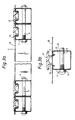
- Figure 2 is a front view of a panel shown as
numeral 2 in Figure 1. - Figure 3a is an enlarged end view taken in vertical section along line AA' of the panel shown in Fig.2.
- Figure 3b is a view of panel member shown as B in Fig 3a prior to application of sealing
member 13. - Figure 4 is a front view taken in vertical section of the corner of the room identified as C in Fig 1.
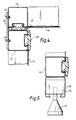
- Figure 5 is a front view taken in vertical section of a levelling foot for use in relation to the room shown in Fig. 1
- Figure 6 is a view taken in vertical section of part of an alternative form of a panel frame.
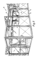
- Figure 7 is a perspective view of a room formed from an alternative form of panelling.
- With reference to the Figs. 1 to 5 the operating theatre shown generally as numeral 1 comprises a number of panels which are joined adjacent one another to form side walls and a ceiling. The panels are exemplified by
panel 2 which consists of fourpanel members continuous recess 8. In the complete theatre 1 the recesses of all the panel members are directed inwards since this has been found to assist cleaning. However in other structures the recesses can be outwardly directed. Each member is provided with a pair ofbolt holes 9 & 10 so as to enable adjacent panels to be secured to one another bybolts 11. The construction of the panel is then completed by stretching over the space defined by the four opposing panel members a sheet offlexible sheet 12 material made for example from a synthetic polyacrylate resin. The sheet must also cover the shoulders 7 of the panel members. The sheet material is then forced into engagement with the shoulders of the member by use of a sealingmember 13. The latter acts as an elongate plug and comprises a strip of resilient synthetic plastics material for example polyvinyl chloride which is provided with a pair of diverginglegs 14. When the legs are pressed against the sheet the latter is forced into the recess and at the same time the legs are compressed together. As a result the material is pressed continuously along its length, firmly against the shoulders 7 of the member 6 by the spring-like action of thelegs 13. When the material has been secured on all its four sides by the panel members it is maintained under tension. - Each panel can be covered with sheet material separately and the completed panels assembled adjacent to one another and secured together by bolts. Alternatively the unclad panel frames can be assembled and bolted together after which a single sheet of the material of sufficient size can be applied to the assembly of unclad panels. Fig. 3a illustrates an arrangement in which a continuous sheet of
material 12 extends frompanel 2 to adjacent panels on both sides. - The theatre is provided with a ceiling formed from panels similar to those described above. The ceiling panels are connected to the wall panels in the manner depicted in Fig.4 in which wall and
ceiling panel members 41 & 42 are secured together by means of aplate 43 which is secured bybolts 44 & 45 to the walls of the panel members. Sheets ofplastics material 46 & 47 are secured by sealingmembers 48 & 49 to the respective panel members, the top of sealingmember 48 acting as an additional seal between the twopanel members 41 & 42. - In order to ensure that air in the theatre is maintained at the required standard of purity a combined fan and
filter 49 is mounted on two ceiling panel members as shown in Fig 1. - The theatre is provided with a hinged
door 50 which can be constructed from the same materials used in the construction of the wall and ceiling panels. Any leakage into the room of unfiltered air under or round the door is prevented by operating thefan 49 at a rate which ensures a slight positive pressure within the theatre. - In the event of erection of the theatre having to be carried out on an unlevel surface the lower horizontal panel members can be provided with levelling feet. Alternatively as shown in Fig. 5 the lower
wall panel members 51 can be bolted to asupport member 52 similar in construction to a panel member and containing ablock 53 made of metal or plastics and threaded to receive alevelling foot 54. If desired the whole structure can be mounted on castors so that it can be moved from one location to another in which case the castors are preferably provided with a locking arrangement so as to enable the theatre to be secured in a required location. - A particular advantage of rooms which are made according to the present invention resides in the fact that the components are constructed under factory conditions away from the location where they are to be assembled. Actual assembly can be carried out cleanly and quickly on site with the simplest of tools and involving very much reduced disturbance compared with conventional methods of construction.
- The rooms and other structures can be used for a wide variety of purposes besides operating theatres for example, for animal and plant breeding, for the manufacture and assembly of micro-electronic components. Outdoor buildings can be made also for example mushroom houses, greenhouses, dutch lights and temporary enclosures for spectators. An important advantage of the present buildings is that they can be made from relatively few different types of components. Consequently both manufacturers and stockists of the components can practice considerable economies in their manufacture and remain capable of satisfying widely differing requirements of their customers.
- The shapes and dimensions of the panel members can be varied depending upon the likely stresses to which the structure is to be subjected. The members can be straight or curved. Compound members can be used which utilise two sheets of material to provide a
cavity 68 as illustrated in Fig.6. In thisfigure panel members 61 & 62 similar to those described above are secured together byspot welds 63 or other convenient fixing means so that the recesses are directed away from each other.Flexible sheets 64 & 65 are then secured over the recesses by sealingmembers 66 & 67. Thespace 68 can either be left empty or filled with some material for example a thermal insulant. In general members having greater weight and strength will be required for out-of-door use compared with structures of similar size for use under cover. The shape of the sealing members can also vary. In general the sheet material should be anchored continuously within the panel member by a sealing member which acts like an elongate plug and forms a push-fit connection with the panel member. This enables the sheet to be brought into tension whilst it is being fixed to the panel member. The precise nature of the anchorage of the sheet material to the panel member depends upon the thickness of the sheet and the degree of its flexibility. When thin plastic sheets of plastics having thicknesses up to about 450 microns are used, the legs or stem of the sealing member tends to push the sheet into the recess and the sheet generally will pass round the stem or the legs as shown in Fig.3a. However with less flexible sheets for example sheets of painted steel having a thickness of about 500 microns the sheet is generally unable to enter the recess to the same extent. Nevertheless it can become anchored satisfactorily by becoming trapped between the head of the sealing member and the shoulder of the recess. Consequently when less flexible sheets are used the sealing member should preferably have a flattened head as illustrated in the figure. - Various kinds of sheet material can be used depending upon the use for which the structure is required. Sheet material made of a synthetic plastics material for example a polyacrylate, polyvinyl chloride, polyethylene, polypropylene, polyester etc have been found very satisfactory. The material can be transparent or opaque or act as a barrier to ultraviolet radiation. The material can also be made of natural textile fibres and take the form of nets made of natural or synthetic fibres or filaments. The material can even be flexible wire mesh or sheets of metal for example aluminium or steel. Metal sheets are preferably painted either to protect the metal surface from corrosion or for decorative purposes.
- Black plastics sheeting is preferable for use in the construction of mushroom houses. For other purposes a tinted material or netting is preferred to provide shade. A fine mesh whether of synthetic plastics or wire is useful where protection from insects is required. A particular advantage of the present method of fixing the sheet material is that parts of the sheeting can be replaced very easily in the event of damage or to be replaced entirely if the use of the room is to be altered. Furthermore the continuous nature of the anchorage of the sheet not only improves the appearance of the structure but in addition reduces the danger of tearing when the structure is subjected to wind.
- The use of panels incorporating metal sheets provides privacy where this is necessary because of the opacity of the metal. However more importantly they can also constitute flame barriers between adjacent spaces within a building. Metal sheets are liable to flex very readily and during this action an undesirable amount of noise may be emitted. In order to reduce the flexibility of the sheet and to impart greater strength to it the sheet can be subjected to an embossing process during which it is provided with a three dimensional structure. For example the main area of the sheet can be crimped or corrugated or provided with a ridges whilst leaving margins of the sheet unembossed so that they can be secured to the panel members by the sealing member. This aspect of the invention is illustrated in Fig.7 in which a room shown generally as
numeral 70 is provided with a wall which comprisesupper panels 71 andlower panels 72. The upper panels comprise recessed panel members to which has been secured transparent sheets of polyvinyl chloride. The lower panels comprise similar panel members to which has been secured a paintedsheets 73 of steel having a thickness of about 500 microns. The sheets have been embossed withcross bracing ridges 74 prior securing them to the panel members. The lower panels provide not only an element of privacy but they also constitute a flame barrier.
Claims (12)
- A portable room incorporating at least one panel comprising a plurality of panel members each of which is provided with a continuous shouldered recess, the members being connected together detachably to define a space covered by a flexible sheet of material which is held in engagement with the shoulders of the panel members by a sealing member comprising a flexible strip of shaped material.
- A portable room according to Claim 1 wherein the flexible sheet is made from plastics.
- A portable room according to either of Claims 1 and 2 wherein the flexible sheet is transparent.
- A portable room according to Claim 1 wherein the flexible sheet is made from metal.
- A portable room according to any one of the preceding claims wherein the flexible sheet material is embossed prior to application to the panel members.
- A portable room according to any one of the preceding claims wherein the panel comprises a plurality of compound panel members to which are secured spaced apart sheets of flexible material.
- A portable room according to any one of the preceding claims wherein the flexible strip of shaped material is an elongate plug.
- A portable room according to any one of the preceding claims which is an operating theatre.
- A portable room according to any one of the preceding claims incorporating a fan.
- A portable room according to any one of the preceding claims incorporating levelling feet.
- A portable room according to any one of the preceding claims provided with a door incorporating a panel as contained in any one of the preceding claims.
- Portable rooms as hereinbefore described with particular reference to the drawings.
Applications Claiming Priority (2)
| Application Number | Priority Date | Filing Date | Title |
|---|---|---|---|
| GB8928703 | 1989-12-20 | ||
| GB898928703A GB8928703D0 (en) | 1989-12-20 | 1989-12-20 | Portable room |
Publications (1)
| Publication Number | Publication Date |
|---|---|
| EP0434384A1 true EP0434384A1 (en) | 1991-06-26 |
Family
ID=10668206
Family Applications (1)
| Application Number | Title | Priority Date | Filing Date |
|---|---|---|---|
| EP90313897A Withdrawn EP0434384A1 (en) | 1989-12-20 | 1990-12-19 | Portable room |
Country Status (2)
| Country | Link |
|---|---|
| EP (1) | EP0434384A1 (en) |
| GB (2) | GB8928703D0 (en) |
Cited By (7)
| Publication number | Priority date | Publication date | Assignee | Title |
|---|---|---|---|---|
| GB2287486A (en) * | 1994-03-01 | 1995-09-20 | Viking Saunas Limited | An enclosed structure, e.g. Steam Room |
| DE29708225U1 (en) * | 1996-09-17 | 1997-06-26 | Laflow Reinraumtechnik Gmbh & | Clean room tent |
| WO2000061895A1 (en) * | 1999-04-12 | 2000-10-19 | Robert Bosch Gmbh | Clean room |
| EP0894540A3 (en) * | 1997-07-28 | 2001-03-07 | Haden, Inc., | Contaminant shield from aluminium extrusion |
| EP1344878A1 (en) * | 2002-03-13 | 2003-09-17 | Jan Christoph Herbert | Pavilion with walls that can be filled up |
| DE202004011401U1 (en) * | 2004-07-21 | 2005-03-31 | Colandis Gmbh | Clean-room repair enclosure with integral filter, dismantlable frame with has filter module suspended form ceiling and having apron-like extensions to give specific air flow |
| CN110700633A (en) * | 2018-07-10 | 2020-01-17 | 富士施乐株式会社 | Partition and kit thereof |
Citations (2)
| Publication number | Priority date | Publication date | Assignee | Title |
|---|---|---|---|---|
| US4188764A (en) * | 1978-04-03 | 1980-02-19 | Gode Charles R | Prefabricated greenhouse structure |
| FR2570161A1 (en) * | 1984-09-10 | 1986-03-14 | Derrien Bernard | Tubular load-bearing profiled part for a framework and devices for linking to the profiled part |
Family Cites Families (4)
| Publication number | Priority date | Publication date | Assignee | Title |
|---|---|---|---|---|
| GB836158A (en) * | 1957-07-26 | 1960-06-01 | Bath & Company Ltd T | Improved building structures and their method of fabrication |
| GB1326011A (en) * | 1969-06-17 | 1973-08-08 | Andrews G A H | Enclosures for machinery and the like |
| AU2387688A (en) * | 1987-09-07 | 1989-04-17 | Malcolm James Dobson | Building panel |
| GB8900328D0 (en) * | 1989-01-07 | 1989-03-08 | Grimalder Ltd | Fixing sheet material |
-
1989
- 1989-12-20 GB GB898928703A patent/GB8928703D0/en active Pending
-
1990
- 1990-12-10 GB GB9026811A patent/GB2239464A/en not_active Withdrawn
- 1990-12-19 EP EP90313897A patent/EP0434384A1/en not_active Withdrawn
Patent Citations (2)
| Publication number | Priority date | Publication date | Assignee | Title |
|---|---|---|---|---|
| US4188764A (en) * | 1978-04-03 | 1980-02-19 | Gode Charles R | Prefabricated greenhouse structure |
| FR2570161A1 (en) * | 1984-09-10 | 1986-03-14 | Derrien Bernard | Tubular load-bearing profiled part for a framework and devices for linking to the profiled part |
Cited By (9)
| Publication number | Priority date | Publication date | Assignee | Title |
|---|---|---|---|---|
| GB2287486A (en) * | 1994-03-01 | 1995-09-20 | Viking Saunas Limited | An enclosed structure, e.g. Steam Room |
| GB2287486B (en) * | 1994-03-01 | 1997-07-30 | Viking Saunas Limited | An enclosed structure eg a steam room |
| DE29708225U1 (en) * | 1996-09-17 | 1997-06-26 | Laflow Reinraumtechnik Gmbh & | Clean room tent |
| EP0894540A3 (en) * | 1997-07-28 | 2001-03-07 | Haden, Inc., | Contaminant shield from aluminium extrusion |
| WO2000061895A1 (en) * | 1999-04-12 | 2000-10-19 | Robert Bosch Gmbh | Clean room |
| EP1344878A1 (en) * | 2002-03-13 | 2003-09-17 | Jan Christoph Herbert | Pavilion with walls that can be filled up |
| DE202004011401U1 (en) * | 2004-07-21 | 2005-03-31 | Colandis Gmbh | Clean-room repair enclosure with integral filter, dismantlable frame with has filter module suspended form ceiling and having apron-like extensions to give specific air flow |
| CN110700633A (en) * | 2018-07-10 | 2020-01-17 | 富士施乐株式会社 | Partition and kit thereof |
| US11542701B2 (en) | 2018-07-10 | 2023-01-03 | Fujifilm Business Innovation Corp. | Booth |
Also Published As
| Publication number | Publication date |
|---|---|
| GB8928703D0 (en) | 1990-02-28 |
| GB9026811D0 (en) | 1991-01-30 |
| GB2239464A (en) | 1991-07-03 |
Similar Documents
| Publication | Publication Date | Title |
|---|---|---|
| US4038791A (en) | Window greenhouse | |
| EP1105589B1 (en) | Prefabricated plastic shed and components therefor | |
| EP0069473B1 (en) | A fence assembly | |
| EP1156178B1 (en) | Partition former for inhabitable spaces and use thereof | |
| EP0434384A1 (en) | Portable room | |
| US7216853B2 (en) | Solid barrier system | |
| US5529289A (en) | Plastic multi-functional privacy fence | |
| WO1994027480A1 (en) | Indoor barrier device assembly | |
| US5608997A (en) | Vertical log building and method for constructing the same | |
| CA2539582A1 (en) | Panel with hidden attachment means | |
| US4594828A (en) | Building construction system including a profile extrusion used as a universal structural member and assembly clips therefor | |
| US20070169426A1 (en) | Window template and art viewer | |
| US4604827A (en) | Hinged window-guard assembly | |
| JP2756894B2 (en) | Dome-shaped building | |
| GB2548677A (en) | Modular containment and screening system | |
| EP0654114B1 (en) | A free mountable device with a vertical wall construction constituting a rail | |
| US3534514A (en) | Shelter using semi-rigid flexed walls | |
| JPH084535Y2 (en) | fence | |
| GB2495902A (en) | Security panel for use in construction of secure structures within buildings | |
| JPH01219246A (en) | Outer lighting frame | |
| AU606657B2 (en) | Open panelling | |
| CA2203984C (en) | Vertical log building and method for constructing the same | |
| RU3777U1 (en) | MODULAR SPATIAL BUILDING CONSTRUCTION | |
| JPH0291384A (en) | Execution method for building such as bay window | |
| JP2003096958A (en) | Mounting structure for curtain wall |
Legal Events
| Date | Code | Title | Description |
|---|---|---|---|
| PUAI | Public reference made under article 153(3) epc to a published international application that has entered the european phase |
Free format text: ORIGINAL CODE: 0009012 |
|
| AK | Designated contracting states |
Kind code of ref document: A1 Designated state(s): AT BE CH DE DK ES FR GR IT LI LU NL SE |
|
| 17P | Request for examination filed |
Effective date: 19910521 |
|
| 17Q | First examination report despatched |
Effective date: 19920212 |
|
| STAA | Information on the status of an ep patent application or granted ep patent |
Free format text: STATUS: THE APPLICATION IS DEEMED TO BE WITHDRAWN |
|
| 18D | Application deemed to be withdrawn |
Effective date: 19930814 |